Abstract
Consistent performance of Li metal electrode (LME) relies on well-distributed current across the electrode surface. Lithium plating and dendrite growth are challenging issues for LME performance in high-energy rechargeable Li battery (RLB) development. The morphology of Li plating is affected by local current density variations on LME. A three-dimensional RLB cell model is used to study current density variations induced by cathode particle size. Smaller cathode particles show lower variances in the current density distribution throughout the separator. The results suggest particle size could affect uniformity of Li plating, propensity for dendrite formation and ultimately cycle life of RLB.
Export citation and abstract BibTeX RIS

This is an open access article distributed under the terms of the Creative Commons Attribution Non-Commercial No Derivatives 4.0 License (CC BY-NC-ND, http://creativecommons.org/licenses/by-nc-nd/4.0/), which permits non-commercial reuse, distribution, and reproduction in any medium, provided the original work is not changed in any way and is properly cited. For permission for commercial reuse, please email: oa@electrochem.org.
Lithium metal has a high theoretical specific capacity making it an ideal candidate for high specific energy, rechargeable Li metal batteries (RLB). However, growth of dendrites, internal short-circuits, formation of inactive Li, and side reactions that consume electrolyte are drawbacks that need to be overcome to fully capitalize on the benefit of using a Li metal electrode (LME).1–4 Some of the current research looking into suppressing dendrite growth includes surface film control, reformulating electrolytes, alloy formation, and improving separator microstructures.5–9 The development of electrochemical models to predict critical conditions is crucial to better understand possible solutions.2
Experimental studies show strong dependence on local current density for Li deposition and stripping, in contrast with an ideal uniformity.10–12 Models developed for dendritic growth rates under a variety of conditions show dependence on local current densities in the formulations.13–15 Improvements in both computational power and increased resolution of techniques for experimental observations, provide opportunity to expand beyond one-dimensional electrochemical models16,17 to describe RLB failure. Three-dimensional models could yield insight into capacity fade, battery performance and failure by resolving cell structure.18–20 Building on the advances which have been made for three-dimensional Li-ion battery (LIB) modeling, this study looks at modeling of RLBs with specific interest on local current density variability. The three-dimensional model is briefly described, followed by results and analysis of the current density distribution across the separator.
Theoretical
This work considers a cell with an LME and a LiNi0.6Mn0.2Co0.2O2 (NMC-622) cathode. Figure 1 shows the geometry for the three-dimensional configuration for three different particles sizes with randomly generated particles – 9 μm is used in actual cell construction while 6 and 3 μm are theorized manufacturing possibilities. The mesh contains 25 million cells, this was increased to 47 million to check spatial convergence, and the change in the standard deviation of the current was 4%. The random structure was used to avoid issues that can occur with structured three-dimensional packing configurations.19 The cell domain is a cross-sectional area of 625 μm2, with a total thickness of 78 μm; parameters are in Table I. The electrolyte is LiPF6 in propylene carbonate/ethylene carbonate/dimethyl carbonate (PC/EC/DMC); parameters are in Table II. The present RLB cell model is derived from a LIB model that is based on concentrated solution theory.21 The RLB cell model is set up using a finite volume approach (STARCCM+),22 which solves for the current density, electrical potential, and Li concentration. The separator structure is not explicitly modeled, but calculates the effective transport based on tortuosity and porosity. The model contains equations across the solid electrolyte interphase (SEI) described with Butler-Volmer kinetics. Details of the formulation can be found throughout literature.20–22
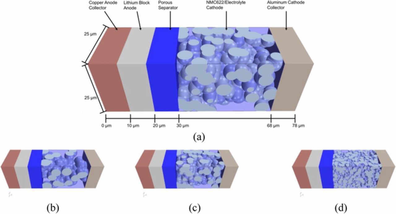
Figure 1. RLB model diagram (a) and cathode with 9.0 (b), 6.0 (c), 3.0 (d) μm particle diameters.
Table I. Model Parameters.
| Property | Cathode | Separator | Anode |
|---|---|---|---|
| Particle Diameter (μm) | 3.0/6.0/9.0 | ||
| Maximum Concentration (mol cm−3) | 0.059493 | ||
| Porosity | 35% | 40% | |
| Tortuosity | 1.877 | 1.58 | |
| Thickness (μm) | 38 | 10 | 10 |
| Diffusion Coefficient (cm2 s−1)23,24 | 5.0 × 10⁻¹¹ | ||
| Electrical Conductivity (S cm−1)24 | 0.1 | 1.1 × 10⁷ | |
| Stoichiometry, at SOC = 0 | 97.2 | ||
| Stoichiometry, at SOC = 100 | 32.8 | ||
| Capacity (mAh g−1) | 178 | ||
| Collector | Aluminum | Copper |
Results and Discussion
Simulations were ran at 25°C with C/20 (0.371 A m−2), this low charge rate isolates particle effects from temperature dependent effects from heating at high charge rates. Current field vectors for the model at each cathode particle size are shown in Figures 2a–2c at the central plane. Differences in transport properties between phases distort the field so that it is uneven. The electrical field in the separator becomes more uniform moving from the cathode toward the anode. However, full uniformity of the current is not achieved, which may promote uneven Li deposition. This trend is shown through the standard deviation of the current density in Figure 2d.
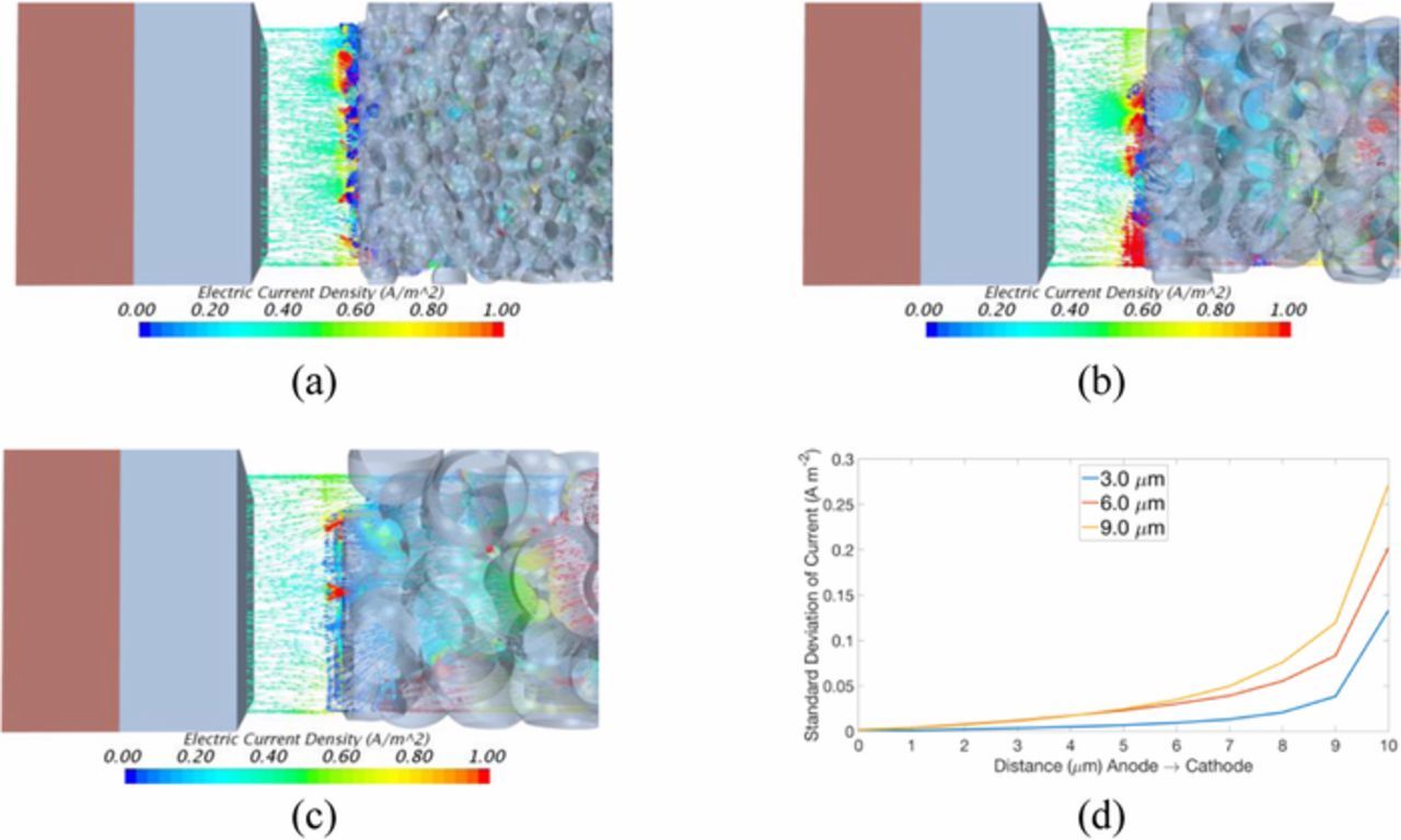
Figure 2. The centerline current density vectors for (a) 3.0, (b) 6.0, (c) 9.0 μm particle diameter and (d) standard deviation of the current density from anode to cathode, in the separator.
The normalized histograms for the current distribution across the electrolyte separator are shown in Figure 3 at five locations for each simulation. The left column shows the 9 μm case, the central shows the 6 μm case, and the right shows the 3 μm case. The variance is highest at the cathode-separator interface, and becomes more even moving from the cathode through the separator to the anode. Higher variability occurs as cathode particle size increases due to enhanced distortion of the current density flow. The current density contours are shown in Figure 4 at five locations across the separator for each simulation. In agreement with Figure 3, the sparsely populated larger particles on the cathode-interface for the 9.0 μm particle sizes cause the largest variance in current density. For the smaller cathode particles, the SEI equations are applied on a larger total surface area, and thus the conservation of charge at the SEI boundary provides a more uniform current distribution in the cathode.
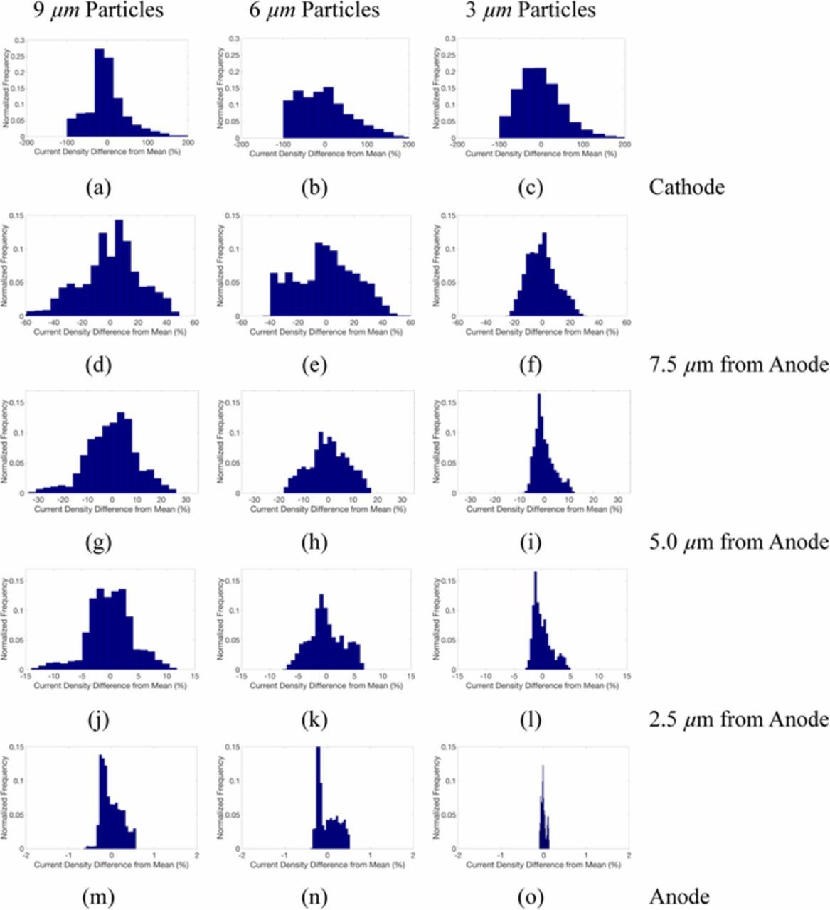
Figure 3. Histograms of current density at (a-c) separator-cathode interface for 9.0, 6.0, 3.0 μm particle diameter, respectively, and at (d-f) 7.5 μm (g-i) 5.0 μm (j-l) 2.5 μm from the anode surface, and at the LME-separator interface (m-o).
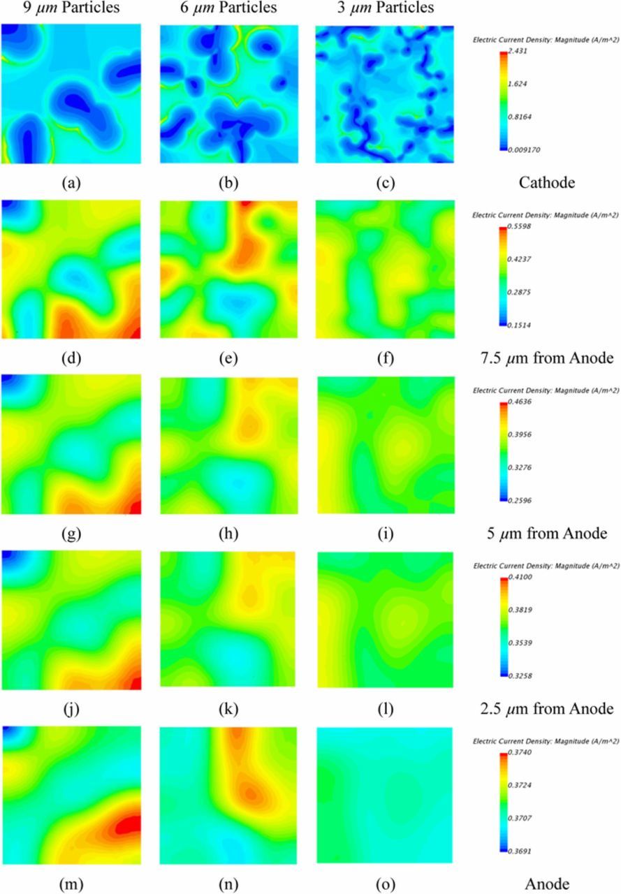
Figure 4. Contours of current density at (a-c) separator-cathode interface for 9.0, 6.0, 3.0 μm particle diameter, respectively, and at (d-f) 7.5 μm (g-i) 5.0 μm (j-l) 2.5 μm from the anode surface, and at the LME-separator interface (m-o).
In the first 5 μm from the cathode-separator interface a rapid reduction in the range of the current density variation occurs from ∼200% down to 20% (shown in Figures 3). The standard deviation reduces closer to the LME-separator interface but distinct variations in current density are still observed. The regions of variation at the LME-separator interface effectively align with active material particles which reside at the cathode-separator interface where the lowest current density is seen. Given that localized current density drives the amount and morphology of electrodeposited Li, the higher variances in the localized current density at the LME surface may eventually lead to higher deviations from uniform Li deposition and more pronounced dendritic growth during repeated cycles.
One design mechanism for RLBs to increase the specific energy of a cell is to reduce the thickness of the separator. However, as shown in Figures 2–4, the current density does not immediately even out once the current flows into the separator. Thus reductions in the thickness of the separator, result in a greater current density variation at the LME-separator interface. With respect to Li electrodeposition morphology this increase is likely to shorten cell cycle life. As RLB designs advance, the present work highlights that in addition to advances in active materials and electrolyte, attention needs to be paid to the electrode architecture and cell design to balance electrode separation distance and cathode particle size to enhance cycle life while maintaining high specific energy.
Conclusions
This study illustrates an important aspect of how local current density on a LME could be affected by the porous structure of the cathode and its particle size. A three-dimensional LME/NMC-622 cell model with cathode particle size variation was used to illustrate how current inhomogeneity could potentially impact electrode stability and cell performance. The smaller cathode particles produce less variation in local current density distribution. The cathode particle size may impact localized Li deposition rate and morphology at the LME-separator interface. It is important to emphasize that this characteristic local current density variability is critical to high energy density RLB designs. As we push for thinner separator in the cell designs, we should also manage the current distribution on the electrode surface in the porous electrode structure to prevent early cell failures.
Acknowledgments
Research has been supported by the Assistant Secretary for Energy Efficiency and Renewable Energy, Office of Vehicle Technologies of the U.S. Department of Energy through the Advanced Battery Materials Research (BMR) Program (Battery500 Consortium). Idaho National Laboratory is operated by Battelle Energy Alliance under Contract No. DE-AC07-05ID14517 for the U.S. Department of Energy.
ORCID
Alexander W. Abboud 0000-0001-6789-0077
Eric J. Dufek 0000-0003-4802-1997
Boryann Liaw 0000-0001-7431-1977