Abstract
Derived from the Pseudo Two-Dimensional mathematical structure, a simplified electrochemical and thermal model of LiFePO4-graphite based Li-ion batteries is developed in this paper. Embedding the porous electrode theory, this model integrates the main design parameters of Li-ion systems and its partial differential equations mathematical structure makes it a promising candidate for battery management system (BMS) applications and comprehensive aging investigations. Based on a modified Single-Particle approach, the model is used to simulate and discuss capacity restitution in galvanostatic charges and discharges at various rates and temperatures. Constant high-rate solicitations similar to fast charge of plug-in electric vehicles or electric vehicles, are experimentally tested and simulated with the present model. Also, thermal issues occurring during these specific operating conditions are quantitatively pointed out. The concept of current-dependent spherical particle radius is used to obtain good agreement with experimental data related to galvanostatic charges and discharges. The capabilities and limits of this preliminary modeling work are discussed in detail and ways to extend the potentialities of this approach to BMS applications are proposed.
Export citation and abstract BibTeX RIS
Over the past 15 years, Li-ion batteries have received much attention for their application as leading candidates for next generations of electric vehicles (EVs), plug-in electric vehicles (PHEVs), even hybrid electric vehicles (HEVs), and also as a promising alternative for energy storage. In that context, it is essential to proceed with detailed mathematical modeling of the battery technology, to produce the optimum cell design, management and configuration. Even though the various aspects of performance required from a battery in terms of power and energy can be assessed experimentally, battery modeling can be of valuable use to explore electrical limitations and thermal behavior of a candidate technology. For all these purposes, refined electrochemical models are being more and more investigated. In comparison with empirical modeling approaches, physics-based models can provide detailed information for the optimization of a battery with respect to the efficient use of energy and are thus promising candidates for next generations of battery management systems (BMS). Initially developed by Newman and Tiedemann,1 the Pseudo Two-Dimensional (P2D) model is the reference in electrochemical battery models in terms of theoretical integration of mechanisms and prediction capabilities. The P2D model was especially validated on galvanostatic discharge operating conditions. It generally gives good results but requires heavy computing resources, which prohibits its use for onboard BMS application.2 In order to limit computing time for simulation purposes, mathematical reduction of the P2D model have led to the development of simplified electrochemical models like the Porous electrode model with the Polynomial approximation (PP) and the Single Particle (SP) model. Santhanagopalan et al.3 reviewed the main electrochemical battery models comparing the P2D, PP and SP models in terms of computing efficiency for cycling performance purposes. Comparisons were performed on basic discharge profiles. In the simplified SP model, the Li concentration in the electrolyte phase is assumed to be uniform along the cell. This hypothesis can strongly limit the capabilities of these models for design and specification issues, especially for high-load solicitations where mass transport limitations in liquid phase are not negligible.3 Neglecting electrolyte phase can also limit the model applicability for aging studies. Similarly to the SP model, Di Domenico et al. have recently developed an average model (AM) for charge estimation in BMS applications, with fixed electrolyte concentration, as detailed below.4
The present work focuses on the development of a simplified and computationally efficient electrochemical and thermal Li-ion model, which integrates the main design parameters of battery and some specific features of LiFePO4 and graphite electrodes, with the aim to predict the voltage dynamics and capacity restitution for LiFePO4-graphite Li-ion batteries under slow or fast galvanostatic charge and discharge operating conditions. Indeed, from a practical point of view for EVs and PHEVs, continuous high loads solicitations correspond to fast charge operating conditions that can daily occur. Fast charge situations have to be carefully investigated through both experimental and numerical tests to design safe and durable Li-ion battery packs.
In the first section of the paper, theoretical considerations, hypotheses and the mathematical structure of the model are presented. Specific features and behaviors of electrode materials such as hysteresis of LiFePO4 and graphite electrodes are pointed out. In the second part, the experimental calibration of the model is presented with a focus on the choice of electrolyte properties. Then, electrical and thermal model predictions are compared with experimental data on various charge and discharge profiles. The concept of a current-dependent radius of the particle reported in the literature on the SP model is used to account for the difference in capacity restitution after charge or discharge at same rate. Finally, the third part is dedicated to a simulation study on constant current fast charging protocols. The capabilities and limits of this simplified electrochemical and thermal model are highlighted and different ways to improve the present model are also mentioned.
Model Development
State-of-the-Art on electrochemical and thermal battery models
Literature on electrochemical and thermal modeling of battery systems is quite extensive. In the porous electrode theory, the electrode is treated as a superposition of two continua, namely the electrolytic phase and the solid matrix. The solid matrix is modeled as microscopic spherical particles, where the Li ions diffuse and react at the surface of the spheres. A classical 1D representation of a Li-ion battery is shown in Fig. 1. The complete electrochemical system is composed of three porous media, namely the negative electrode, the separator and the positive electrode. The porosity of the three regions is filled by the electrolyte liquid phase. Considering the LiFePO4-graphite system, the electrochemical storage reactions in charge can be represented by Eqs. 1–2.
![Equation ([1])](https://content.cld.iop.org/journals/1945-7111/159/9/A1508/revision1/jes_159_9_A1508eqn1.jpg)
![Equation ([2])](https://content.cld.iop.org/journals/1945-7111/159/9/A1508/revision1/jes_159_9_A1508eqn2.jpg)
During discharge operating conditions, the reverse reactions occur in the cell. The nominal physical and chemical phenomena occurring in Li-ion systems can be expressed by the mass conservation of Li+ species (Eqs. 3–4), charge conservation (Eqs. 5–6) and electrochemical kinetics (Eqs. 7–8) that are presented in Table I. All these equations are the framework of the P2D electrochemical model. Non isothermal electrochemical models have also been addressed by Gu and Wang5 in a 1D model at the electrode level whereas other researchers have introduced a simple lumped-parameter thermal model for the full cell.6,7 As presented in Table II, the energy balance (Eq. 14) integrates both generated (Eq. 15) and exchanged with environment (Eq. 16) thermal fluxes. Generated thermal flux takes into account both the irreversible and reversible contributions. Coupling between the electrochemical and thermal models is performed thanks to a classical Arrhenius law expressed by Eq. 17 for all mass transport and kinetic parameters. Readers can refer to the aforementioned literature for further detailed description of the mathematical developments. Based on the P2D mathematical structure, the theoretical set-up of the simplified model is detailed below.
Table I. 1D electrochemical model equations.7
| Physical and chemical mechanisms | Eq. | Boundary conditions |
|---|---|---|
| Solid phase: conservation of Li+ species |
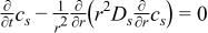 | 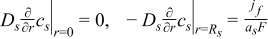 |
| Electrolyte phase: conservation of Li+ species |
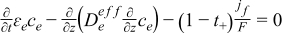 | 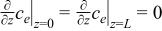 |
| Solid phase: charge conservation |
 |  |
| Electrolyte phase: charge conservation |
 |  |
| Electrochemical kinetics | 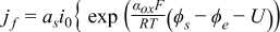 | |
 | ||
| Electrode overpotential |
 | |
| Electrolyte ionic diffusivity |
 | |
| Electrolyte ionic conductivity |
 | |
| Electrolyte ionic diffusional conductivity |
 | |
| Solid phase electronic conductivity |
 | |
| Specific interfacial surface area |
 |
Table II. Heat transfer and energy balance equations.
| Heat transfer and energy balance | Eq. |
|---|---|
| Energy balance |
 |
| Thermal flux generated during operation |
 |
| Transferred thermal flux to environment |  |
| Coupling between 1D electrochemical and lumped thermal models | |
| Arrhenius law applied to mass transport and kinetic parameters Ψ |  |
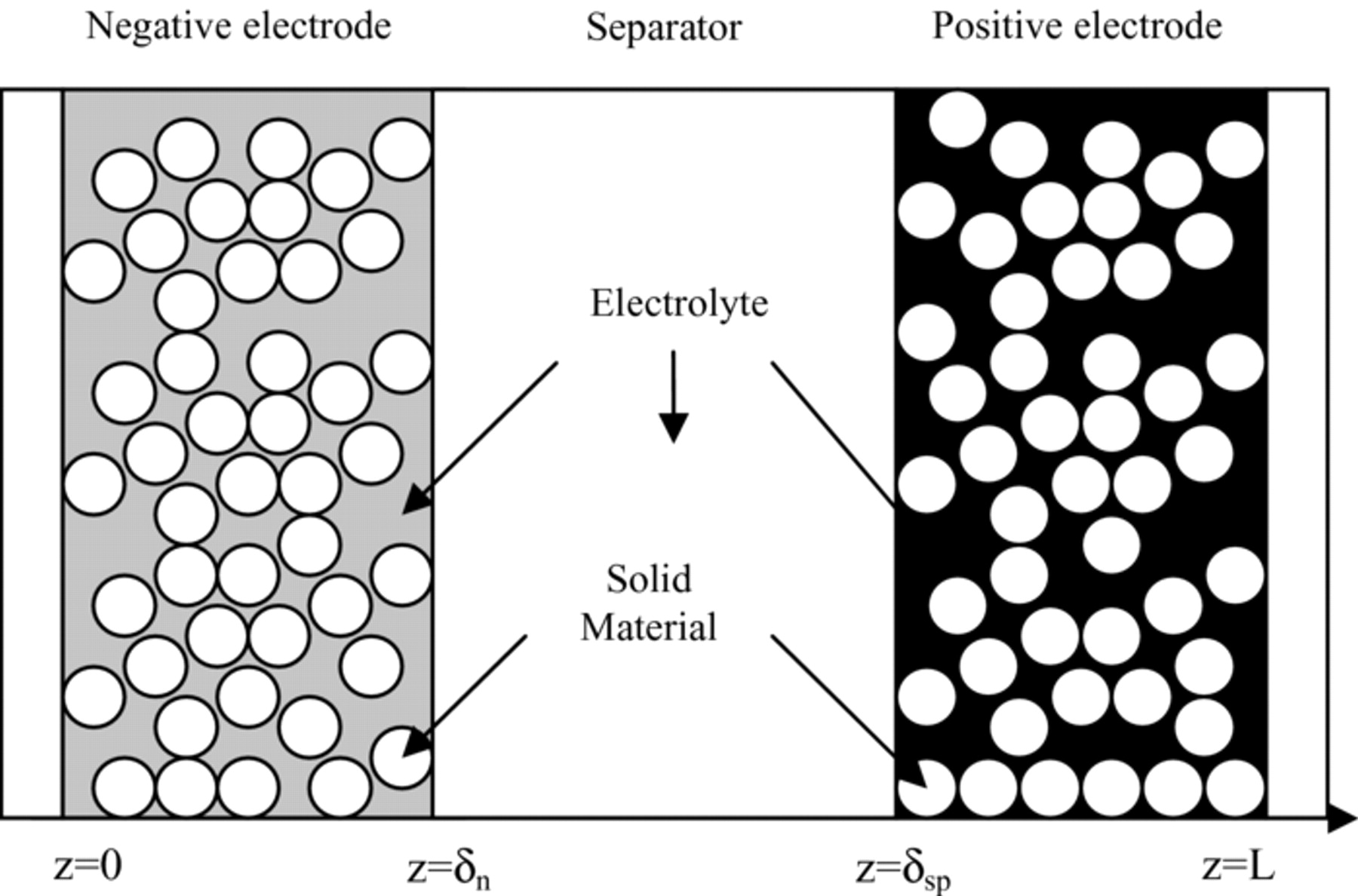
Figure 1. Schematic of 1D (z-direction) electrochemical cell model.
Within the framework of electrochemical models, one has to consider the properties of electrode materials in detail. Indeed, even with the P2D model, non satisfactory results can be obtained if specific features of materials are not considered. Among all the electrode materials used in Li-ion batteries, LiFePO4, which is a phase transformation material as initially reported by Padhi et al. in 1997,8 is one of the most promising chemistry due to its intrinsic safety, low cost and electrochemical performances. Nevertheless, LiFePO4 material presents specific features like partial solid solution regions or differences in capacity restitution according to the charging or discharging path which makes the modeling of this material difficult. During the past decade, electrochemical modeling works on LiFePO4 have been addressed to understand the complex mechanism of Li ions insertion/extraction that proceeds through a two-phase transition between a Li-poor LixFePO4 phase (α-phase) and a Li-rich LiyFePO4 phase (β-phase). Srinivasan and Newman9 reported the first shrinking-core model, but in order to obtain a good agreement with experimental data on discharge curves at different current rates, they had to consider a particle size distribution (PSD) effect with spherical particles of two different sizes. The original shrinking-core model was then extended to the planar geometry by Wang et al.10 who obtained good results on discharge operating conditions up to 20C. The authors extended the original shrinking-core model by introducing the Li diffusion in both phases and the interface mobility as a model parameter. This model was then used to design new galvanostatic and potentiostatic intermittent titration techniques (GITT and PITT) to determine the diffusion coefficients of the respective phases in the composite (α+β).11 Nevertheless, shrinking-core models can be difficult to program and issues related to the management of multiple interfaces can appear for complex charge/discharge profiles. Alternatively, Thorat et al.12 proposed the concept of phase-change diffusivity to account for LiFePO4 behavior in charge and discharge, introducing a concentration-dependent diffusion coefficient of Li in the solid phases. Moreover, the authors considered the resistive-reactant feature of insulating LiFePO4, introducing the PSD effect with four different particle sizes. The resistive-reactant concept was further developed by Safari and Delacourt who studied, with a simplified electrochemical model, the (dis)charge path dependence, the asymmetry and the electronic resistance distribution of this material.13 Good agreement was obtained with experimental data until 1C charge and discharge rates. Later, Delacourt and Safari14 proposed a simplified mathematical model to explain the insertion/extraction mechanism of Li ions for LiFePO4 material until 2C. In this simplified approach based on the SP model without considering PSD effect, the authors determined relationships between particle radius and current density to fit experimental charge and discharge curves. In this work, the radius dependencies upon current were tentatively explained with the mosaic concept.
Simplified theoretical model and hypotheses
In order to design a simplified electrochemical model, the AM developed by Di Domenico et al.4 was adopted and extended. The AM consists in neglecting the solid concentration distribution along the electrode and considering the material diffusion, for each electrode, inside a representative solid particle at which the Li concentration is equal to the mean value of the concentration over the electrode thickness,  . Accordingly, the faradaic current density per unit volume, jf, is equal to the mean value of the current density over the electrode thickness,
  . Therefore, the AM model considers a single particle for each electrode as the SP model but, instead of algebraic-differential equations in the SP model, the AM deals with Partial Differential Equations (PDE), well suited for the design of BMS functions. However, as previously mentioned, no distribution of the Li concentration in the electrolyte phase was considered in Ref. 4. In order to extend the AM mathematical structure, the mass conservation equations in the electrodes (Eq. 3) and in the electrolyte (Eq. 4) are used with the AM assumption, enabling the variation of Li concentration in the solid phase,
  , and in the liquid phase, ce(z), to be computed at any time.
The current density per unit volume in each electrode satisfies the following spatial integrals:
![Equation ([18])](https://content.cld.iop.org/journals/1945-7111/159/9/A1508/revision1/jes_159_9_A1508eqn18.jpg)
![Equation ([19])](https://content.cld.iop.org/journals/1945-7111/159/9/A1508/revision1/jes_159_9_A1508eqn19.jpg)
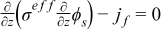
where δn and δp are the thicknesses of the negative and positive electrodes, respectively. With this assumption, the charge conservation equations (Eqs. 5 and 6) can be solved analytically as a function of the spatial coordinate z, giving:
![Equation ([20])](https://content.cld.iop.org/journals/1945-7111/159/9/A1508/revision1/jes_159_9_A1508eqn20.jpg)
![Equation ([21])](https://content.cld.iop.org/journals/1945-7111/159/9/A1508/revision1/jes_159_9_A1508eqn21.jpg)
for the negative electrode region,
![Equation ([22])](https://content.cld.iop.org/journals/1945-7111/159/9/A1508/revision1/jes_159_9_A1508eqn22.jpg)
for the separator region, and
![Equation ([23])](https://content.cld.iop.org/journals/1945-7111/159/9/A1508/revision1/jes_159_9_A1508eqn23.jpg)
![Equation ([24])](https://content.cld.iop.org/journals/1945-7111/159/9/A1508/revision1/jes_159_9_A1508eqn24.jpg)
for the positive electrode region.
Cell voltage, kinetics and mass transport overpotentials
As described by Di Domenico et al.,4 the voltage of a battery at time t, V(t), is expressed as the sum of different terms, namely thermodynamic potentials, U, and overpotentials, η, appearing as current is passed through the system. According to Eq. 8:
![Equation ([25])](https://content.cld.iop.org/journals/1945-7111/159/9/A1508/revision1/jes_159_9_A1508eqn25.jpg)
In Ref. 4, the electrolyte concentration is uniform in the battery and, therefore, there is no diffusion overpotential in the electrolyte. Moreover, the thermodynamic potentials, Up and Un, of the positive and negative electrodes have been estimated from the Li concentration, css, at the surface of the single particle representing each electrode. In our work, the distribution of the electrolyte concentration is considered in order to deal with high load solicitations. Mass transport in both solid and liquid phases is taken into account by replacing the overpotential boundary values η(L) and η(0) by the average values of the overpotentials for each electrode. These overpotentials are due to the kinetic and diffusion phenomena occurring, respectively, at the solid-electrolyte interfaces and within the solid and electrolyte phases. In addition, Up and Un are estimated from the Li concentration, cbs, in the bulk (r = 0) of the single particle. The battery voltage can then be expressed as:
![Equation ([26])](https://content.cld.iop.org/journals/1945-7111/159/9/A1508/revision1/jes_159_9_A1508eqn26.jpg)
where θbp and θbn denote the normalized Li concentrations in the bulk of the positive and negative electrodes:
![Equation ([27])](https://content.cld.iop.org/journals/1945-7111/159/9/A1508/revision1/jes_159_9_A1508eqn27.jpg)
In these equations, cs,n,max and cs,p,max are the maximum Li concentration in the negative and positive electrodes. By the way, the normalized bulk concentrations θbp and θbn correspond to the coefficients x and y used in Eqs. 1 and 2.
To express the electrode overpotential, the approach used by Bergveld et al. was adopted in this work.15 The electrode overpotential η can be expressed as the sum of the kinetic and diffusion overpotentials at both electrodes:
![Equation ([28])](https://content.cld.iop.org/journals/1945-7111/159/9/A1508/revision1/jes_159_9_A1508eqn28.jpg)
![Equation ([29])](https://content.cld.iop.org/journals/1945-7111/159/9/A1508/revision1/jes_159_9_A1508eqn29.jpg)
This mathematical description of the charge transfer overpotentials facilitates the quantification, in first approximation, of the different contributions to the potential distribution in the battery. In the following, the kinetic and mass transport overpotentials are successively defined.
Firstly, to express the kinetic overpotential at each electrode as a function of the current intensity, the oxidation and reduction charge transfer coefficients αox and αred are assumed to be equal to α = 0.5 for both electrodes. Then, considering Eq. 7 for the positive and negative electrodes with the assumption of the average model, and replacing the electrode overpotentials by the kinetic overpotentials, one gets:15
![Equation ([30])](https://content.cld.iop.org/journals/1945-7111/159/9/A1508/revision1/jes_159_9_A1508eqn30.jpg)
![Equation ([31])](https://content.cld.iop.org/journals/1945-7111/159/9/A1508/revision1/jes_159_9_A1508eqn31.jpg)
The positive and negative kinetic overpotentials can be expressed as:
![Equation ([32])](https://content.cld.iop.org/journals/1945-7111/159/9/A1508/revision1/jes_159_9_A1508eqn32.jpg)
![Equation ([33])](https://content.cld.iop.org/journals/1945-7111/159/9/A1508/revision1/jes_159_9_A1508eqn33.jpg)
where
![Equation ([34])](https://content.cld.iop.org/journals/1945-7111/159/9/A1508/revision1/jes_159_9_A1508eqn34.jpg)
![Equation ([35])](https://content.cld.iop.org/journals/1945-7111/159/9/A1508/revision1/jes_159_9_A1508eqn35.jpg)
In these equations, the exchange current densities are sometimes considered to be given by the following expressions:1,2,4
![Equation ([36])](https://content.cld.iop.org/journals/1945-7111/159/9/A1508/revision1/jes_159_9_A1508eqn36.jpg)
![Equation ([37])](https://content.cld.iop.org/journals/1945-7111/159/9/A1508/revision1/jes_159_9_A1508eqn37.jpg)
However, for sake of simplicity and as performed in several reported battery models, the exchange current densities have been set as constants.7,16
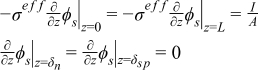
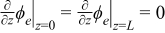
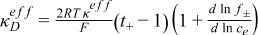
Secondly, the overpotentials due to mass transport (diffusion and migration) in the electrolyte and inside the solid active material have to be defined. In the electrolyte phase, the mass transport overpotential is obtained as the difference between the potentials of the electrolyte phase taken at the extremities of the electrodes. Eq. 23 expressed at z = L results in
![Equation ([38])](https://content.cld.iop.org/journals/1945-7111/159/9/A1508/revision1/jes_159_9_A1508eqn38.jpg)
Under the assumption of constant electrolyte concentration along the z axis, the last part of Eq. 38 can be seen as a representation of electro-migration inside the electrolyte. This term is generally known as ohmic resistance and can be determined thanks to electrochemical impedance spectroscopy for instance.17 This will be discussed in detail in the model calibration section. Neglecting the electric resistance of connectors and the conductivity of the solid phases in the electrodes, the ohmic resistance, Rohm, can thus be expressed as a function of the geometric area of the electrodes, A, the thicknesses of the electrodes and separator, δn, δp, δsep, and the electrolyte effective conductivity, κeff, in the three regions:
![Equation ([39])](https://content.cld.iop.org/journals/1945-7111/159/9/A1508/revision1/jes_159_9_A1508eqn39.jpg)
The effective conductivities mentioned in Eq. 38 can be defined as a function of the Li concentration, ce, and volume fractions, ɛe and ɛf, of the electrolyte and filler, and from the Bruggman exponent, Brugg, of each region, as follows:
![Equation ([40])](https://content.cld.iop.org/journals/1945-7111/159/9/A1508/revision1/jes_159_9_A1508eqn40.jpg)
![Equation ([41])](https://content.cld.iop.org/journals/1945-7111/159/9/A1508/revision1/jes_159_9_A1508eqn41.jpg)
![Equation ([42])](https://content.cld.iop.org/journals/1945-7111/159/9/A1508/revision1/jes_159_9_A1508eqn42.jpg)
In the solid phases, the mass transport overpotential is approximated as a function of the bulk, cbs, and surface, css, Li concentrations of the spherical particles. Neglecting migration in the solid phases, the diffusion overpotential in the negative and positive solid phases is expressed as in Bergveld et al.'s work:15
![Equation ([43])](https://content.cld.iop.org/journals/1945-7111/159/9/A1508/revision1/jes_159_9_A1508eqn43.jpg)
![Equation ([44])](https://content.cld.iop.org/journals/1945-7111/159/9/A1508/revision1/jes_159_9_A1508eqn44.jpg)
where θsp and θsn denote the normalized Li concentrations at the surface of the positive and negative electrodes:
![Equation ([45])](https://content.cld.iop.org/journals/1945-7111/159/9/A1508/revision1/jes_159_9_A1508eqn45.jpg)
The state of charge (SOC) of the full cell, SOCbat, can be expressed as a function of the normalized bulk Li concentration in the positive electrode or in the negative electrode, for example:
![Equation ([46])](https://content.cld.iop.org/journals/1945-7111/159/9/A1508/revision1/jes_159_9_A1508eqn46.jpg)
with respect to the negative electrode, where θbn, 0% and θbn, 100% are the normalized Li concentrations in the bulk of the negative electrode, respectively for a fully discharged and fully charged cell.
Rearranging Eq. 26 with Eqs. 28–29, 32–33, 43–44 gives
![Equation ([47])](https://content.cld.iop.org/journals/1945-7111/159/9/A1508/revision1/jes_159_9_A1508eqn47.jpg)
![Equation ([48])](https://content.cld.iop.org/journals/1945-7111/159/9/A1508/revision1/jes_159_9_A1508eqn48.jpg)
Interestingly, one can notice that the cell voltage is directly correlated to the specific design parameters of the system such as the electrode porosities, or to the physical parameters such as the electrolyte conductivity or the active material concentrations. This expression, which distinguishes the main electrochemical phenomena, could be useful in discussing and quantifying the impact of the variations of design parameters during aging.
Thermodynamic potentials and hysteresis phenomenon
Li-ion battery electrodes are often phase transition materials leading to the presence of multiphase regions as lithiation / delithiation proceeds, which greatly complicates the modeling work. Mathematical models for equilibrium potentials of Li-ion battery electrodes can be found in literature. For the main electrode materials like LiCoO2, LiMn2O4, LiFePO4, analytic expressions18 and theoretical thermodynamic laws19,20 have been proposed. Hereafter, detailed information concerning charge and discharge equilibrium potentials of LiFePO4 and graphite materials are given.
During lithiation / delithiation, lattice misfits between different phases are responsible of accommodation energy that can lead to hysteresis phenomenon. It was demonstrated that LiFePO4 electrodes21 and graphite electrodes22,23 show pronounced Open Circuit Voltage (OCV) hysteresis phenomena. Detailed thermodynamic explanations of this phenomenon can be found in Ref. 10 for the LiFePO4 electrode. Dreyer et al.21 reported a permanent hysteresis of approximately 20 mV for LiFePO4. In order to properly model hysteresis phenomena on both electrodes, specific experimental tests were performed on half-cells in this work. The hysteresis phenomena are represented in Fig. 2 for LiFePO4 and graphite materials.
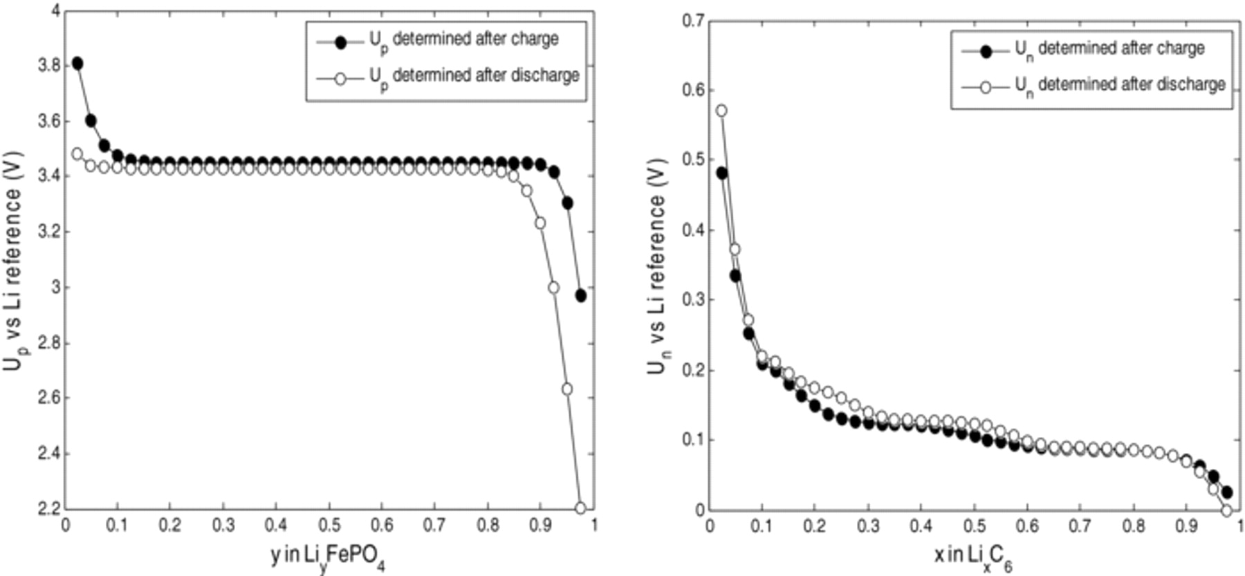
Figure 2. Equilibrium potential of LiFePO4 and graphite electrodes after charge and after discharge.
In the present work, dynamic hysteresis is considered. As the diffusion phenomena in the solid particles have already been considered, the equations reported by Roscher and Sauer24 are adapted to our model as follows:
![Equation ([49])](https://content.cld.iop.org/journals/1945-7111/159/9/A1508/revision1/jes_159_9_A1508eqn49.jpg)
![Equation ([50])](https://content.cld.iop.org/journals/1945-7111/159/9/A1508/revision1/jes_159_9_A1508eqn50.jpg)
![Equation ([51])](https://content.cld.iop.org/journals/1945-7111/159/9/A1508/revision1/jes_159_9_A1508eqn51.jpg)
![Equation ([52])](https://content.cld.iop.org/journals/1945-7111/159/9/A1508/revision1/jes_159_9_A1508eqn52.jpg)
Eq. 52 gives the evolution of the hysteresis factor Γ as a function of the current and of the hysteresis parameter χ, which is determined experimentally and is used to quantify the dynamics of the hysteresis.24 The state value of Γ is limited to the range between 0 and 1, thus Eq. 52 is used within this restricted range. As can be seen in Eq. 49, when the values of Γ are 1 and 0, OCVbat is respectively equal to OCVch and OCVdch. From the thermodynamic equilibrium potentials of each electrode in charge and discharge, and based on the experimentally determined stoichiometries θ defined in Eq. 46, the open circuit voltage of the full cell, OCVbat, can be reconstructed (Eqs. 46, 50–51) for both charge and discharge, as represented in Fig. 3.
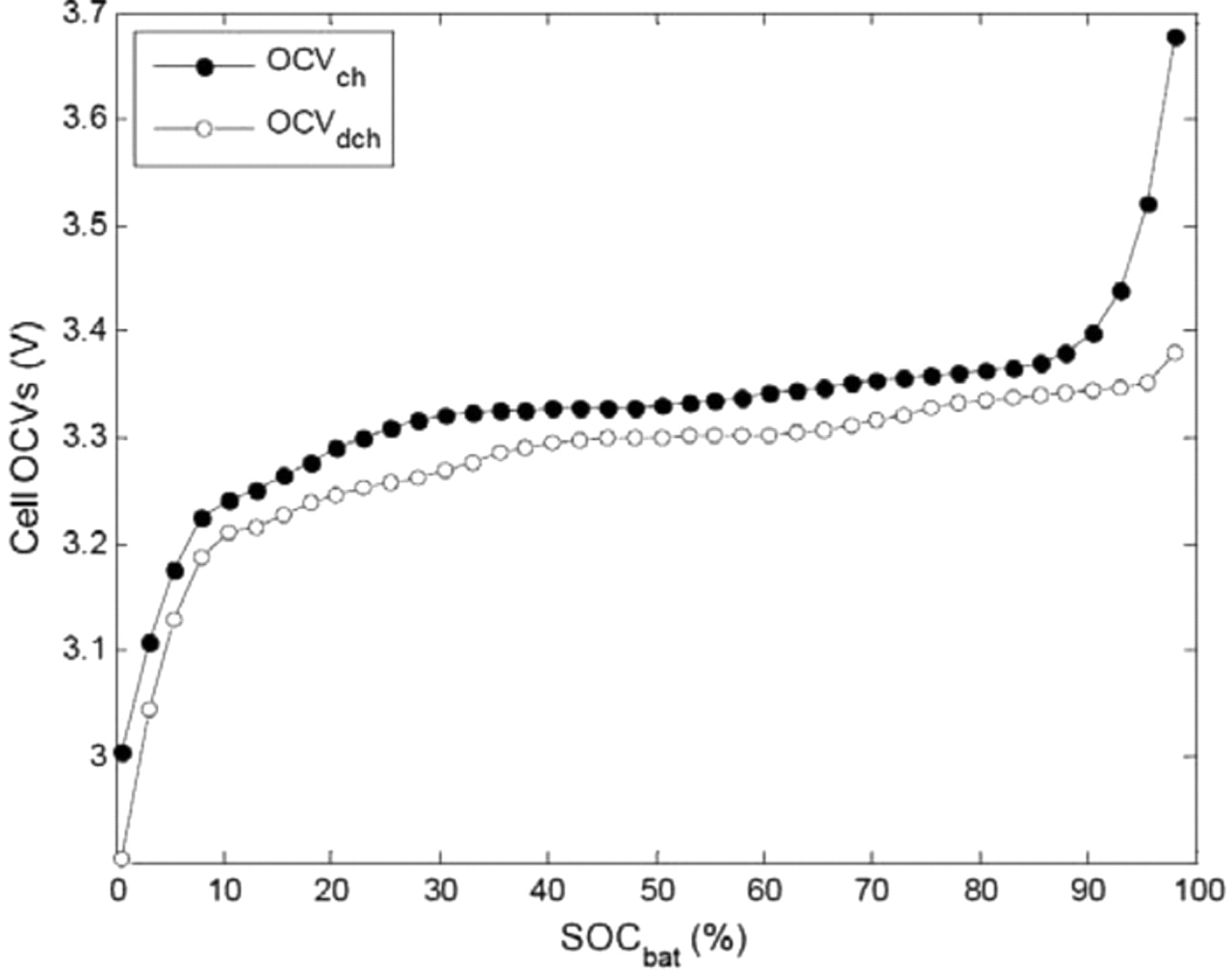
Figure 3. Reconstructed OCVs of the full cell in charge and discharge.
Lumped parameter energy balance and internal temperature estimation
The thermal behavior of Li-ion cells has been widely investigated in order to optimize thermal management and to address potential security issues. In this work, a simple lumped parameter energy balance was considered as described in Table II. Both irreversible and reversible (entropic) contributions of thermal power generated are considered, as shown in Eq. 15. Thermal properties of electrode materials are also well reported in literature.25,26 The entropic contributions presented in Eq. 15 have been investigated in Ref. 26 for LiFePO4 and Ref. 27 for graphite materials. As reported by Reynier et al.,27 one can observe an hysteresis phenomenon on the entropic heat for graphite electrodes. Entropic contributions can be important especially for low current rates, as shown in Ref. 28 and in the model validation part below. As temperature control is a key point in BMS design to ensure security and long life of the system, an estimation of the internal temperature of the cylindrical cell has to be introduced in the present model. Many authors have investigated the spatial thermal behavior of cylindrical Li-ion battery cells.28,29 Rigorous investigation of the thermal behavior should be carried out through multi-dimensional modeling. However, to limit computing time, the simple thermal model developed by Forgez et al.30 to estimate the internal temperature of the cylindrical system was used in this work. The following equation links the internal temperature, Tint, the skin temperature, Tskin, and the ambient temperature, Tamb:
![Equation ([53])](https://content.cld.iop.org/journals/1945-7111/159/9/A1508/revision1/jes_159_9_A1508eqn53.jpg)
The thermal resistance, Rth,in, modeling the heat transfer inside the cell, can be defined as a function of the thermal conductivity, λcell, and radius, rcell, of the cell:
![Equation ([54])](https://content.cld.iop.org/journals/1945-7111/159/9/A1508/revision1/jes_159_9_A1508eqn54.jpg)
On the other hand, the thermal resistance, Rth,out, modeling the heat transfer between the cell and the environment can be expressed as a function of the Newton convective coefficient, hconv, and the lateral surface of the cylindrical cell Acell:
![Equation ([55])](https://content.cld.iop.org/journals/1945-7111/159/9/A1508/revision1/jes_159_9_A1508eqn55.jpg)
From Eqs. 53–55, the internal temperature can be expressed as:
![Equation ([56])](https://content.cld.iop.org/journals/1945-7111/159/9/A1508/revision1/jes_159_9_A1508eqn56.jpg)
In first approximation, Eq. 56 provides quantitative information about the impact of the cooling system (air cooling, liquid cooling) on the thermal gradients inside the cell. The values of the parameters of the simplified electrochemical and thermal model are presented in the following section.
Model Calibration and Validation
Electrical tests
Experimental work was performed on commercial LiFePO4-graphite cells ANR26650 M1 (2.3 Ah) from A123 Systems. C/10, C/4, C/2, 1C, 2C, 4C, and 8C charges and discharges were performed in a climatic chamber at 0°C, 10°C, 23°C, and 33°C using a multipotentiostat (VMP, Biologic, Claix, France) outfitted with 20 A boosters for high C-rate measurements. For discharge experiments, the initial state of the cells was obtained by charging at a constant current (CC) of 1C until 3.6 V, then a constant voltage (CV) of 3.6 V was maintained until the current was lower than C/20, finishing with a rest period of 4 h (1C-CC-3.6V-CV until I < C/20, rest 4h). Discharges at different rates were then carried out from the same initial state. For charge experiments, the initial state of the cells was obtained by discharging at a constant current of 1C until a cell potential of 2 V, then a constant voltage of 2 V was maintained until the current was lower than C/20, finishing with a rest period of 4 h (1D-CC-2V-CV until I < C/20, rest 4h). Charges at different rates were then carried out from the same initial state.
Electrochemical and thermal model calibration
The experimental characterization of the inherent properties of the materials under study is an integral part of the modeling effort.31 Indeed, parameterization of physics-based models requires multi-level and multi-physics experimental devices, even if some properties of the materials can be found in literature. Electrochemical characterization tests were conducted at both cell and electrode levels. In order to perform tests at the electrode level, some cells were operated in an argon-filled glove box after complete discharge at 2 V. Scanning electron microscopy was performed on both LiFePO4 and graphite electrodes to determine some of the design parameters. Pieces of the recovered electrodes were then separately reassembled in coin cells with a Li-foil counter electrode to determine the open circuit voltage and the electrochemical window for each electrode. For the LiFePO4-graphite system under study, both literature and measured data were collected and reported in Table III.
Table III. Design parameters of the cell.
| Parameter | Symbol | Unit | Positive electrode | Separator | Negative electrode | |
|---|---|---|---|---|---|---|
| Design specifications | Electrode thickness | δ | m | 8 × 10⁻⁵ (m) | 2.5 × 10⁻⁵ (m) | 3.4 × 10⁻⁵ (m) |
| Particle radius | Rs | m | 5.0 × 10⁻⁸ (m) | 5 × 10⁻⁶ (m) | ||
| Active material volume fraction | ɛs | 0.374(a) | 0.55 | 0.587 | ||
| Filler volume fraction | ɛf | 0.0535(a) | 0.0326 | |||
| Electrode plate area | A | m2 | 1.8 × 10⁻¹ (m) | 1.8 × 10⁻¹ (m) | ||
| Solid and electrolyte phase Li+ concentration | Maximum solid phase concentration | cs,max | mol/m3 | 22806 14 | 305553 | |
| Stoechiometry at 0% SOC | y0%, x0% | 0.74(m) | 0.0132(m) | |||
| Stoechiometry at 100% SOC | y100%, x100% | 0.035(m) | 0.811(a) | |||
| Average electrolyte concentration | ce | mol/m3 | 1200(a) | |||
| Bruggman exponent | Brugg | 1.5 | 1.5 | 1.5 | ||
| Kinetic and transport properties | Exchange current density | j0 | A/m2 | 5 × 10⁻² (es) | 0.5(es) | |
| Charge transfer coefficients | αox, αred | 0.5 | 0.5 | |||
| Surface layer film resistance | RSLI | Ω m2 | 0 | 0 | ||
| Solid phase Li diffusion | Ds | m2/s | 5.9 × 10⁻²⁰ 14 | 3.0 × 10⁻¹⁵ 22 | ||
| Electrolyte phase Li+ diffusion | De | m2/s | 2.0 × 10⁻¹⁰ |
a: adjusted, es: estimated, m: measured.
Without considering aging, the charge balance on the cyclable Li can be checked thanks to the following equations:
![Equation ([57])](https://content.cld.iop.org/journals/1945-7111/159/9/A1508/revision1/jes_159_9_A1508eqn57.jpg)
![Equation ([58])](https://content.cld.iop.org/journals/1945-7111/159/9/A1508/revision1/jes_159_9_A1508eqn58.jpg)
Using the data reported in Table III, Eqs. 57 and 58 give a value of 2.32 Ah for the charge capacity of the electrodes, Qp and Qn, which is in good agreement with the nominal capacity of 2.3 Ah given by the cell manufacturer.
Special electrochemical features of LiFePO4-graphite systems such as (dis)charge path-dependence have been investigated and modeled, incorporating particle size distribution and concentration-dependent solid state diffusion coefficient.9,12,13 Moreover, a thermodynamically-consistent correction of the activity could be introduced to refine the present model on the basis of the experimental open-circuit voltages presented in Fig. 2.20 However, the diffusion coefficients in Table III were set as constants to keep the model simple enough for both the positive and negative electrodes.
To precisely model the diffusion overpotential in the liquid phase (Eq. 38), the electrolyte conductivity has to be determined accurately. In this work, due to a lack of data on the electrolyte composition of the LiFePO4-graphite cell investigated, a simple chemical analysis was carried out to determine the composition of the solvent mixture. This analysis indicates ethylmethyl carbonate (EMC) and dimethyl carbonate (DMC) as the main components (ratio 1:1 (w:w)) of the mixture. Unfortunately, the conductivity dependence on Li concentration of this specific composition was not found in literature. However, this electrolyte could be compared to other electrolyte compositions reported in Table IV.
Table IV. References giving the electrolyte conductivity as a function of its composition.
| Electrolyte | Solvent mixture composition | Ratio | Ref. | |
|---|---|---|---|---|
| Literature data | a | EC / DEC | 1:1 (w:w) | 12 |
| b | EC / EMC | 3:7 (w:w) | 17 | |
| c | EC / DMC | 1:2 (v:v) | 33 | |
| d | EC / DMC | 2:1 (v:v) | 16 | |
| e | not given | not given | 7 | |
| f | EC / DMC | 2:1 (v:v) | 32 |
EC: ethylene carbonate, DEC: diethyl carbonate.
The electrolyte conductivity varies as a function of the solvent mixture composition, as shown in Fig. 4. The conductivity curves generally present a maximum around a Li concentration of 1 mol·dm−3. The conductivity models in the literature report values of the solution conductivity κ. The effective conductivity of the electrolyte in the porous media, κeff, can be determined from the Bruggman correction (Eqs. 40–42). The Bruggman exponent can be used to quantify the impact of the porous media on the electrolyte conductivity.33 Indeed, as demonstrated by Doyle for the EC/DMC electrolyte mixture, the variation of the Bruggman parameter from 1.5 to 4.5 can strongly change the effective conductivity.33 The higher the Bruggman coefficient, the lower the effective conductivity. Recently, Thorat et al. quantified the tortuosity in porous Li-ion electrodes and reported different values for the Bruggman exponents ranging from 1 to 3.3.34
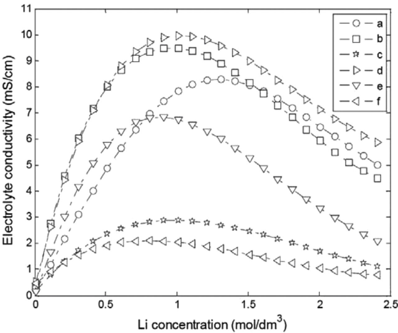
Figure 4. Reported data on electrolyte conductivity as a function of Li concentration (electrolyte compositions "a" to "f" defined in Table IV).
In order to select the most appropriate electrolyte conductivity model from those reported in Table IV, electrochemical impedance spectroscopy (EIS) results performed at 25°C and a SOC of 50% were used. The high-frequency intercept with the real axis in the Nyquist representation of the impedance diagram was used to determine the approximated value of the ohmic resistance. From Eq. 39, and using the design parameters in Table III, the static resistive contributions of the electrolyte in the negative and positive electrodes and in the separator were calculated as a function of the Li concentration. Assuming a Li concentration of 1.2 mol.dm−3 and classical Bruggman exponents of 1.5 due to a lack of available data, a good agreement between the experimental EIS value and the predicted ohmic resistance with the electrolyte model "c" is obtained, as can be seen in Fig. 5.
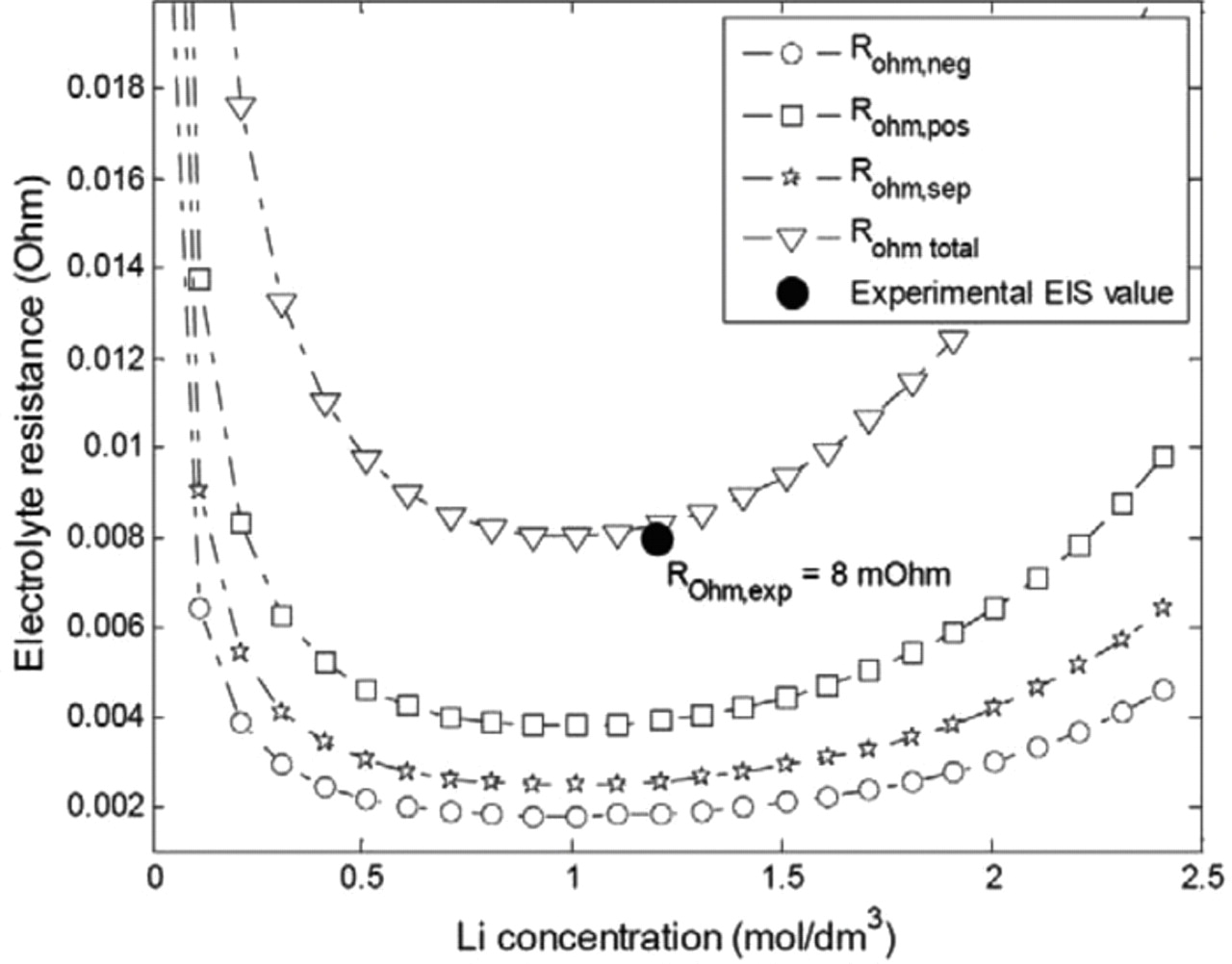
Figure 5. Modeled static ohmic resistance contributions and correlation with the experimental EIS value.
For the thermal model calibration, literature data on thermal parameters were collected and experiments were performed in an adiabatic calorimeter to estimate missing values (see Table V). Temperature dependency is rather complex for the electrolyte. In the present work, temperature dependencies were modeled by a simple Arrhenius law. This assumption can strongly limit the temperature range availability of the model especially under 0°C.
Table V. Thermal parameters of the cell.
| Parameter | Symbol | Unit | Positive electrode | Separator | Negative electrode | |
|---|---|---|---|---|---|---|
| Thermal properties | Charge transfer activation energy | Ea_ct | J/mol | 13000 | 2000028 | |
| Solid phase Li diffusion activation energy | Ea_diff,s | J/mol | 39000(c) from35 43800(c) from36 50700(c) from37 | 3500028 | ||
| Electrolyte phase Li+ diffusion activation energy | Ea_diff,e | J/mol | 26600 | 26600 | 26600 | |
| Electrolyte phase conductivity activation energy | Ea_cond,e | J/mol | 11000(c) | 11000(c) | 11000(c) | |
| Full cell thermal parameters | ||||||
| Thermal resistance | Rth,in | K W−1 | 3.330 | |||
| Newton convective coefficient | hconv | W m−2 K−1 | ∼ 5–10 free convection air cooling ∼ 10–70 forced air convection >100 liquid cooling | |||
| Cell volumic mass | ρc | kg/m3 | 2047(m) | |||
| Heat capacity | Cp | J kg−1 K−1 | 1100(m) | |||
| Cell lateral surface | Acell | m2 | 6.34 × 10⁻³ (c) | |||
| Cell radius | rcell | m | 1.29 × 10⁻² (m) | |||
| Cell mass | m | kg | 0.07(m) | |||
c: calculated, m: measured.
Investigation of the model capabilities for the LiFePO4-graphite system
In this part, as a unique particle size is considered, the capability of the modeling concept proposed by Delacourt et al.14 for the understanding of lithium insertion and deinsertion in LiyFePO4 with a single particle approach is investigated. In Ref. 14, the authors fitted experimental charge and discharge curves of LiFePO4 electrodes using a model with a current-dependent particle radius. In this study, the correlation between the solid state diffusion coefficient, the particle radius and the surface resistance was demonstrated. Mentioning a mosaic model to explain the uncommon dependency of the particle radius as a function of the current regime, the asymmetry between charge and discharge was shown for LiFePO4. As the mathematical structure of the present model is similar to that of the SP model used in Ref. 14, this concept was tested within the framework of our simplified electrochemical and thermal model. This approach was adopted to represent the capacity restitution in charge and discharge. In this preliminary modeling work, the diffusion coefficient in the solid phase was taken as temperature-dependent only and did not vary with concentration. Charge and discharge experiments at C/4, C/2, 1C, 2C, 4C and 8C were performed at 10°C, 23°C and 33°C. Figs. 6 and 7 present the simulation results compared to the experimental data at 23°C.
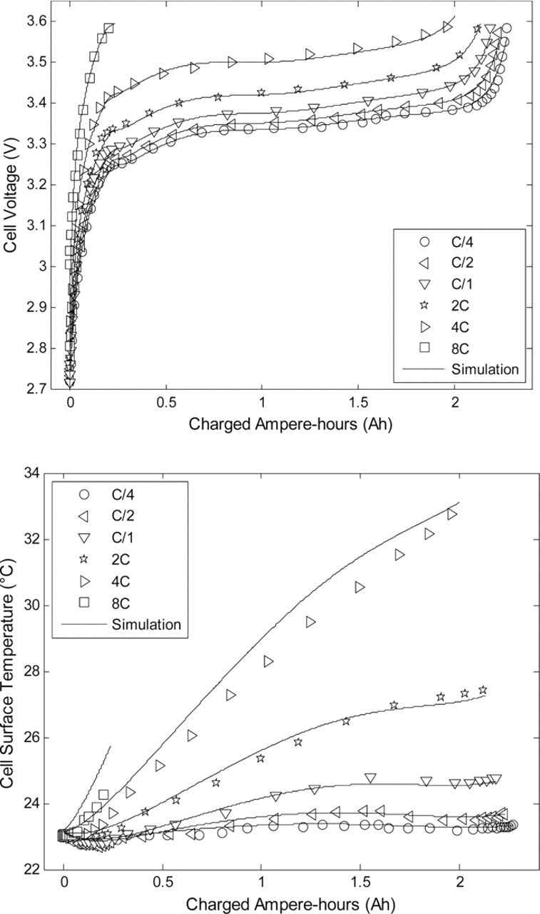
Figure 6. Model predictions of cell voltage and surface temperature compared to experimental data for various charge rates.
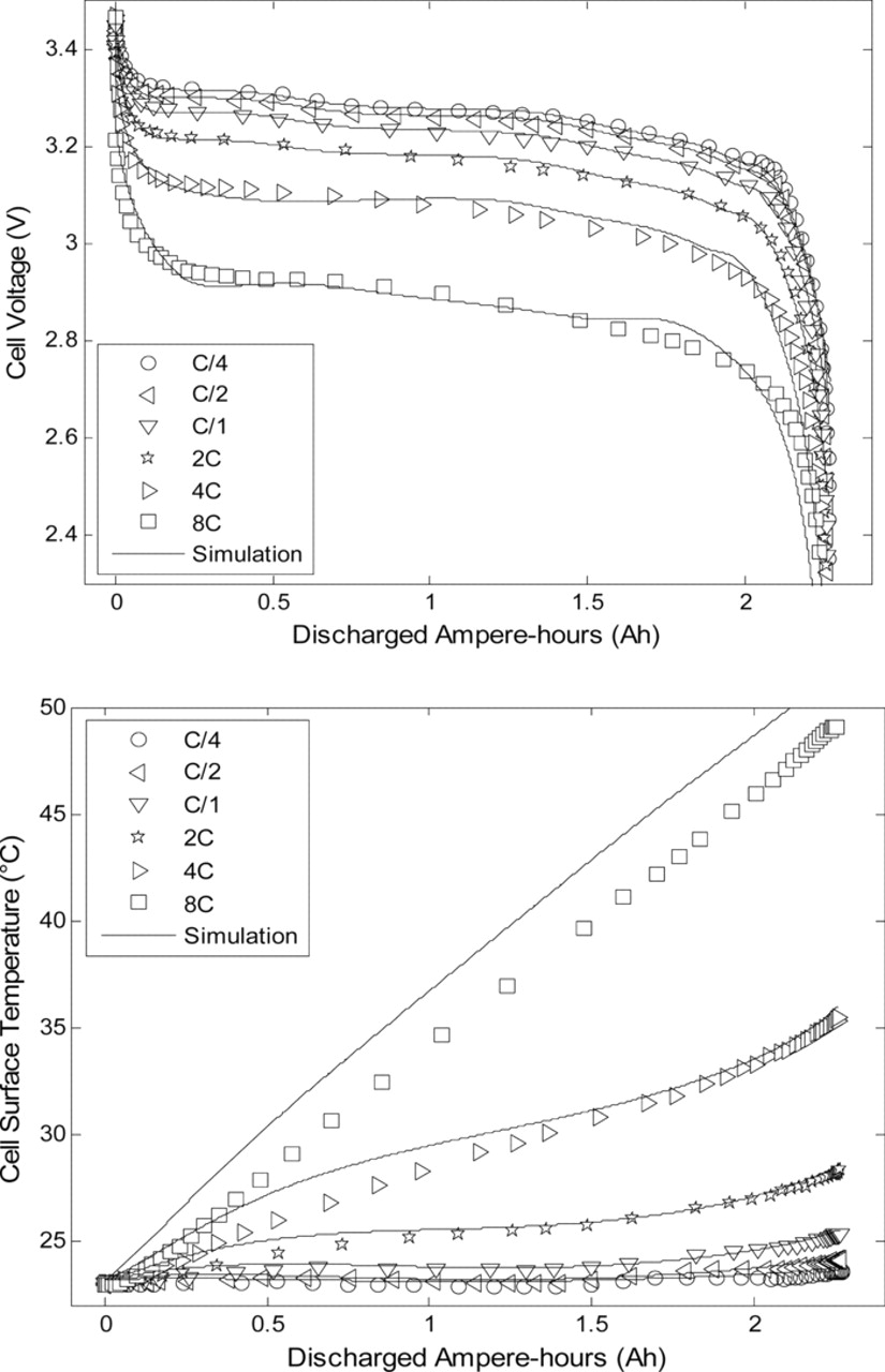
Figure 7. Model predictions of cell voltage and surface temperature compared to experimental data for various discharge rates.
As can be observed in Figs. 6 and 7, deviations between experimental data and model predictions for both cell voltage and skin temperature are under 2% for charge and discharge rates up to 2C over the full SOC range. Larger deviations can be seen for 4C and 8C rates. At a 8C rate the test in charge ended prematurely since the upper cutoff voltage of 3.6 V was reached. To obtain these results, the radius of the spherical particles at the positive and negative electrodes were chosen as adjustment parameters as done in Ref. 14. Indeed, the behavior of the negative electrode is extremely complex as insertion and deinsertion of Li ions occur.20,23 The evolution of the fitted particle radii upon current is shown in Fig. 8. As can be observed in Fig. 8, the higher the current intensity in charge or discharge, the smaller the particle radius. This result could be explained by the fact that smaller particles are filled faster than larger particles. The deinsertion/insertion processes in smaller particles could control the overpotentials of the electrodes especially if it is considered that the extreme SOCs are reached quicker for smaller particles. The mosaic model concept may also explain this phenomenon. In this concept, as described in detail in Ref. 14, boundaries between Li-rich and Li-poor phases could be formed preferentially in place of the growth of existing domains at large current density. The nucleation of multiple phase boundaries could delimit smaller diffusion domains and thus increase the apparent electroactive surface area, hence leading to an apparent reduced particle radius.
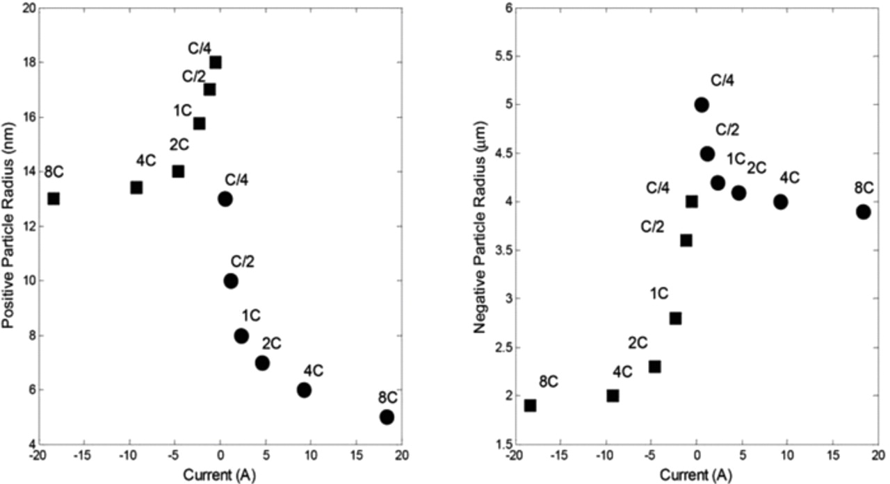
Figure 8. Dependencies of the spherical particles radii of the positive and negative electrodes upon current at 23°C. The squares represent the charge and the circles represent the discharge of the cell.
The present simulation demonstrates that the implementation of a current-dependent radius of the single particles in the simplified electrochemical and thermal model gives good results with respect to capacity restitution from C/4 until 8C rates. These results are in good accordance with those reported in Ref. 14 for LiFePO4. Interestingly, an asymmetry between charge and discharge is observed for both positive and negative materials. Therefore, the model can be considered as validated within the calibration range of C/4 - 8C rates.
Application to Fast Charging Simulations
Fast charging protocols are being more and more investigated for automotive applications since these phases of vehicle battery life are critical in terms of durability, safety and usability. Different protocols are proposed in literature from classical CC-CV protocols to innovative pulse charging or boost charging.38 From a practical point of view, constant power or CC charging protocols are the easiest to implement. In this part, a simulation study is proposed to investigate classical CC fast charging protocols in terms of efficiency, charge duration and thermal aspects. CC charges from 0.5C to 8C were considered on the 2.3Ah commercial LiFePO4-graphite cell (Fig. 9). The initial SOC was set to 0% to investigate the complete fast charge. The upper cutoff voltage was set to 3.6 V, which is the value recommended by the manufacturer. The cooling temperature was considered to be 23°C under free convection. As can be observed in Fig. 9, good performances in cell charging are achieved with respect to the coulomb efficiency with, for example, 1.75 Ah charged at 7C. At current regimes higher than 7C, the upper cutoff voltage was rapidly reached and the experimental charging test prematurely stopped, which explains why the exchanged charge was so small. The same phenomenon can be observed in the experimental and simulation results presented in Fig. 6 with the 8C charge test. The experimental charges exchanged at C/2, 1C, 2C, 4C and 8C rates were measured. Figure 9 shows they are in good agreement with the simulated charges.
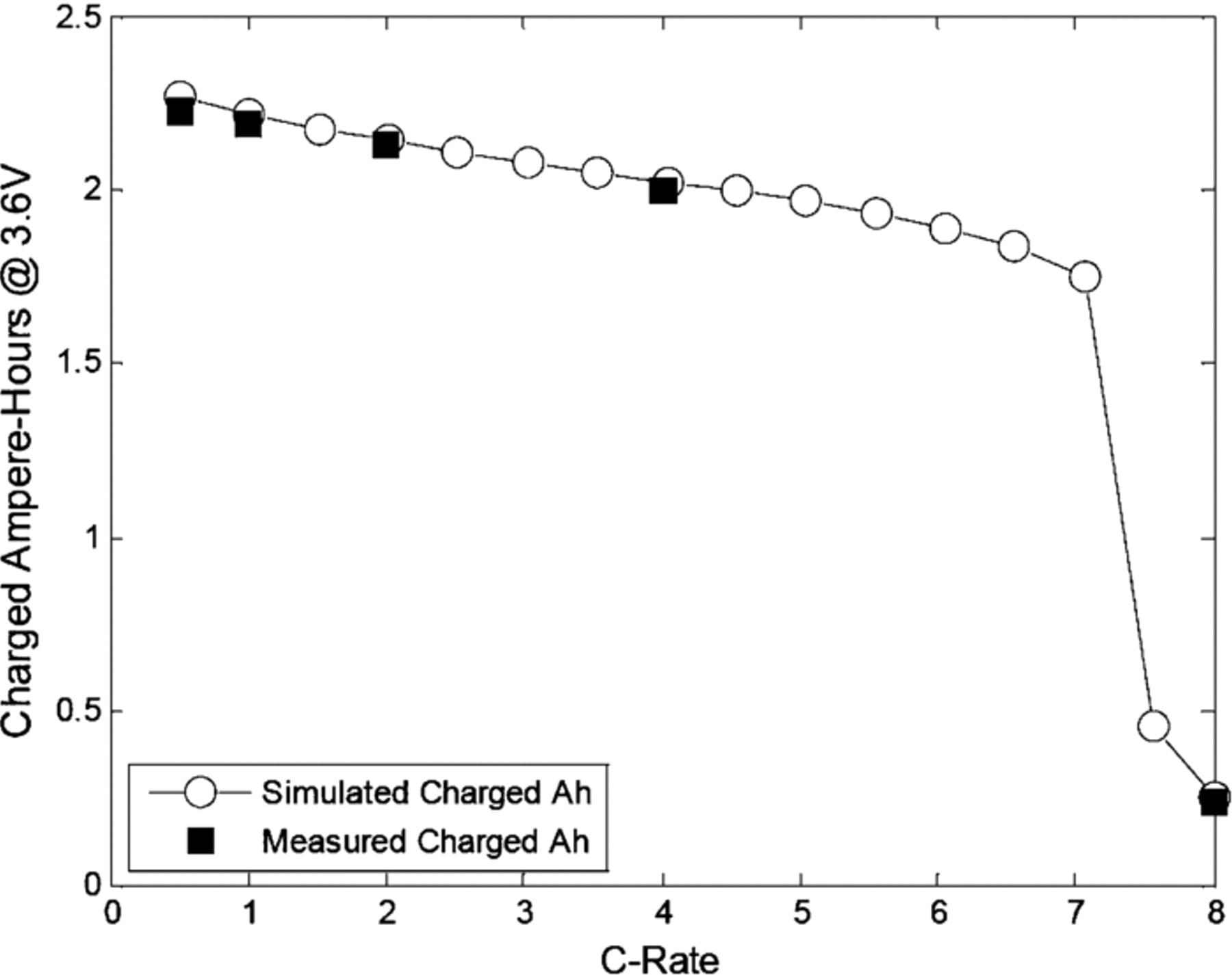
Figure 9. Simulated and experimental charged Ampere-Hours at 3.6 V as a function of C-Rate.
During battery cycling, thermal inhomogeneities between the surface and the core of the cell can develop, potentially leading to safety and life issues.29 In order to investigate the internal temperature evolution during charge operating conditions, Eq. 56 was used to compute the evolution of the core temperature. Figure 10 shows the evolution of the internal and skin temperatures of the cell until the end of charge at 3.6 V as a function of C-rate. Regarding the thermal effects, temperature inhomogeneities actually develop within the cell during fast charge operating conditions, pointing out how critical for safety and life issues fast charging is.29 A thermal gradient of 5°C is obtained in the simulation for a 7C fast charge. As can be observed, the higher the charging rate, the higher the thermal gradient between the surface and the core of the cell under free convection. In addition, Fig. 10 shows that the temperature increase was lower for the 7.5C and 8C rates than for the 7C rate. This comes from the fact that the experimental test and the corresponding simulation rapidly stopped as soon as the upper cutoff limit was reached. The skin temperatures measured at C/2, 1C, 2C, 4C and 8C rates are also presented in Fig. 10. The agreement between the simulated and experimental maximal skin temperatures at the end of the CC charging is satisfactory.
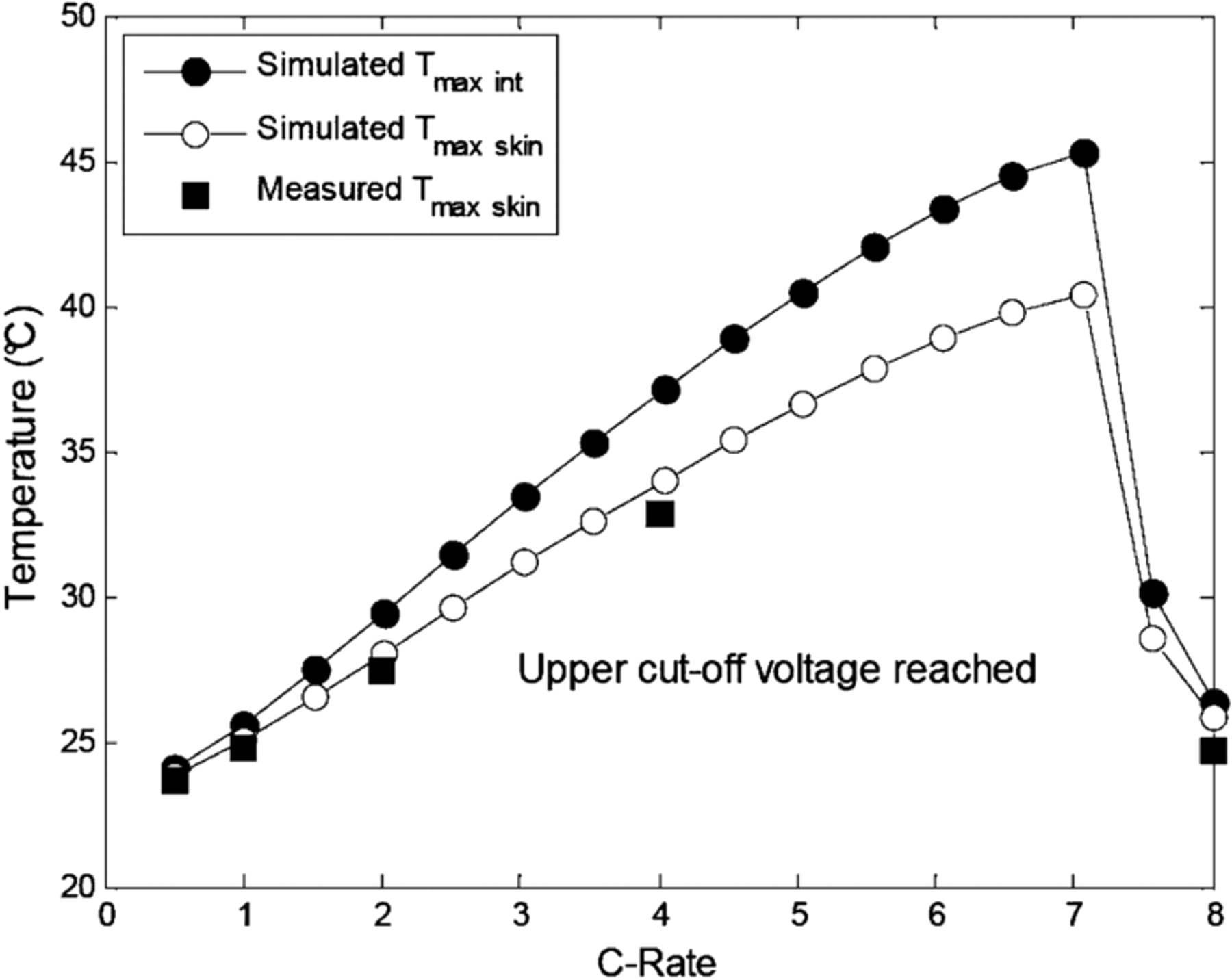
Figure 10. Simulated maximum internal and skin temperatures and experimental skin temperature at the end of charge (3.6 V) as a function of C-rate at a cooling temperature of 23°C.
Charge duration is a critical parameter for EV and PHEV batteries. Trade-offs between charge duration, charge efficiency and aging have to be defined with respect to consumers' requirements and cost constraints. Figure 11 illustrates the relation between charge duration up to 3.6 V and charge efficiency (exchanged charge divided by 2.3 Ah) for the various charging currents investigated. The 5 to 15 min charge range is investigated in detail. It can be seen that the reduction of charge duration leads to a decrease in efficiency due to increased mass transport and kinetic overpotentials.
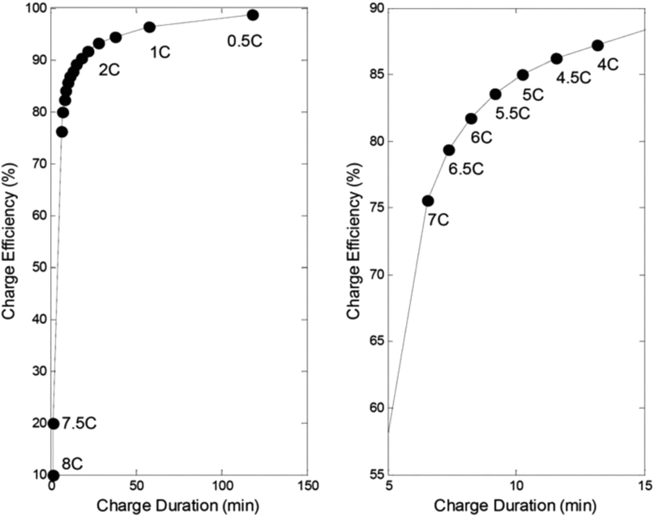
Figure 11. Simulated charge efficiency as a function of charge duration.
The simulation results show good performances of this commercial LiFePO4-graphite system. Simulations and experimental tests demonstrated fast charge capabilities of this system. A 5-minute fast charging protocol could be used to charge 60% of the nominal capacity. However, these results must be confirmed under aging constraints. Moreover, Fig. 11 has to be carefully used since additional electrical power could be demanded to the battery system to ensure its cooling and a safe thermal management. In addition, the efficiency of the entire electrical chain (electronics, inverters...) is not considered in the reported simulation results. Future work will try to integrate Li-ion aging modeling to shed light on life duration issues under specific charge operating conditions.
Conclusions
A simplified electrochemical and thermal model was designed to represent charge and discharge operating conditions of a LiFePO4-graphite commercial 2.3 Ah cell from C/10 to 8C at different temperatures. Using an artificial current-dependent radius for the positive and negative single spherical particles, within the framework of the SP model, the simplified model is able to point out the differences in capacity restitution according to the charging or discharging path of the Li-ion cell. This uncommon dependency upon current had to be introduced since only one particle size was chosen. Using a single-particle diffusion mechanism strongly limits the availability of the simplified model out of the calibration range, especially when simulating dynamic profiles. In order to avoid this problem, the model should integrate particle size distributions in both electrodes. Nevertheless, the simplified model developed here can be used to simulate basic charge and discharge at different rates and different temperatures.
The simple differential mathematical structure of the proposed model makes it a interesting candidate for the design of BMS functions and to optimize galvanostatic fast charging protocols for EVs and PHEVs. A simulation study on CC fast charge protocols was performed with this simplified and experimentally validated model. Quantitative results with respect to charge duration and charge efficiency show good agreement with experimental results. However, the usability and capability of the model, which integrates the concept of current-dependent SP radius, are strictly restricted to continuous galvanostatic current profiles. The present model could be improved to extend its capabilities to complex cycling profiles. Moreover, a physics-based aging model will be developed to account for power and capacity fade of the LiFePO4-graphite cell used in the present work.
Acknowledgments
Special thanks go to Dominique Audigier for his precise work in carrying out the tests on full and half-cells.