Abstract
A test sample incorporating a painted Al alloy panel, uncoated through-hole fasteners, and scribes has recently been shown to provide accelerated response during atmospheric corrosion testing in the field and in laboratory chambers. In this paper, the galvanic current of an AA7075-T6 panel coupled with mixed SS316 and Ti-6Al-4 V fasteners was monitored using a zero-resistance ammeter during 3 weeks exposure in an ASTM B117 chamber or immersed in 5 wt% NaCl solution. SS316 fasteners provided more cathodic current than Ti in both environments and the current in ASTM B117 is higher than in 5 wt% NaCl solution due to greater oxygen availability. The integral of the anodic current with time and optical profilometery (OP) analysis were used to assess the corrosion attack quantitatively for two different coating systems. An acceleration factor was defined to represent the extent of accelerated corrosion for galvanically-connected fasteners. The acceleration factors were in the range of 20–50 for panels with SS316 fasteners and two different coating systems, both with and without a topcoat. The effects of SS316 fasteners were similar for the different coating systems even though the attack morphology was very different.
Export citation and abstract BibTeX RIS

This is an open access article distributed under the terms of the Creative Commons Attribution Non-Commercial No Derivatives 4.0 License (CC BY-NC-ND, http://creativecommons.org/licenses/by-nc-nd/4.0/), which permits non-commercial reuse, distribution, and reproduction in any medium, provided the original work is not changed in any way and is properly cited. For permission for commercial reuse, please email: oa@electrochem.org.
Aluminum alloy (AA) 7075-T6 (UNS A97075) is a high-strength aluminum alloy that is widely used in structural aircraft applications due to the combination of good mechanical properties and light weight.1 However, AA7075-T6 is very susceptible to localized corrosion, including pitting, intergranular and crevice corrosion when exposed to an aggressive environment.2–5 As a result, aluminum alloys for aircraft applications are usually protected from the corrosion attack using multi-layered coating systems.6–8 Because of the generally good corrosion resistant properties by coating systems, a long period is required to observe their degradation or failure even when exposed to aggressive environments, which makes comparison of different coating systems difficult. Therefore, a new accelerated corrosion test sample was design to be efficient and rapid for assessing coatings.9,10 It incorporates a painted Al alloy panel, uncoated through-hole noble fasteners, and scribes in the coating under the fasteners. The introduction of noble fasteners in such sample design activates galvanic corrosion and provides cathodic current to drive severe corrosion attack at scribes after only 567 h exposure to ASTM B117. Galvanic current, morphology and corroded volume data were provided,9,10 but quantitative descriptions of the acceleration extent for galvanically-connected fasteners were not discussed. A quantitative method for assessing degradation is critical to be able to use these new test specimens in research and development, materials specifications, and assessments for the life of coating systems.
Many conventional methods for assessing coatings have been studied in recent decades, including ASTM B117 exposure, field exposure, electrochemical impedance spectroscopy (EIS), and adhesion tests.11–21 The corrosion extent of samples exposed to ASTM B117 or to field environments11,12 is typically only qualitatively assessed, providing only a subjective evaluation of the coatings. EIS can be used to characterize the protective properties of coatings on aluminum alloys by evaluating the low frequency impedance magnitude (|Z|) representing coating resistance and by the coating capacitance, which dominates at higher frequency.13–16 Nevertheless, EIS data have not been well correlated to the field performance. Another very significant coating parameter in the performance of coated metals is the ability to maintain adhesion to a metal substrate in the presence water or electrolyte, which can be determined by different adhesion measurements.17–21 Assessment of adhesion parameter should be a good approach to evaluate coatings, but most adhesion tests are qualitative, performed in dry conditions, non-reproducible, or overestimate adhesion strength as a result of secondary dissipation energies related to test geometry plastic deformation and other reasons.19–21 Therefore, more quantitative and reliable methods are need for rapidly evaluating different coating systems.
In the present work, the galvanic charge and the volume loss of galvanic panels with different coating systems during 3 weeks exposure to ASTM B117 were determined. An acceleration factor was introduced to describe quantitatively the extent of corrosion acceleration from galvanic coupling of the fasteners and substrate.
Experimental
AA7075-T6 panels with size of 150 × 75 × 6.5 mm were used as substrates for the galvanic panels. The arrangement of holes and fasteners was identical to the sample design described previously.9,10 Two rows of 5 mm diameter holes were created on each panel for attaching noble material fasteners. Two different coating systems were tested. One coating system was used previously9,10 and included a chromate conversion coating (CCC) and a chromate epoxy primer (PPG CA7233, MIL-PRF-23377 Type I, Class C coating). The other coating system involved pretreatment with Prekote adhesion promoter and then a Pr-rich primer (Deft 084, MIL-PRF-23377J Type I, Class N coating). The same flat gray polyurethane topcoat (PPG CA9311/F36375, MIL-PRFL-85285D Type IV, Class H coating) was used to paint half of every panel. The samples were cut in half to assess the extent of corrosion attack on primer-only and topcoated panels without interactions between the two sections.
Two types of noble material fasteners and washers (SS316 and Ti-6Al-4V) were used for galvanic coupling with AA7075-T6 panels. The SS316 fasteners were passivated by immersion in 25–45 vol% nitric acid solution at 21 to 32°C for 30 min, rinsing with cold and then hot water and then air drying. The Ti-6Al-4V fasteners were not pretreated before use, and had natural-formed oxide on the surface. To allow measurement of galvanic current between fasteners and the panel, the fasteners were electrically isolated by applying several layers of plastic tape between bolts, nuts, washers and the panel. A numbering scheme was used to identify the four fasteners: #1 and #3 were inserted in the top unscribed holes and #2 and #4 were inserted in the bottom scribed holes, which is identical to the scheme used previously.9,10 Fasteners #1 and #2 were Ti-6Al-4V fasteners; #3 and #4 were SS316 fasteners, as shown in Fig. 1. Some experiments were performed on panels with only stainless steel fasteners.
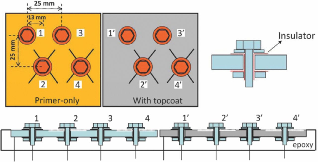
Figure 1. Schematic illustrations of the test sample configurations. Fasteners #1 and #2 are Ti-6Al-4V fasteners; #3 and #4 are SS316 fasteners; or all 4 fasteners are SS316. Note that primer-only and topcoated panels were always mounted together to ensure that the exposure conditions were identical. However, they were electrically isolated from each other.
"X" pattern scribes were manually created across the holes in the bottom row on the panel through to the Al alloy substrate using a carbide scribe and the fasteners were attached. The distance from the end of scribes to the edge of the washer under each fastener was about 10 mm. The width of the carbide scribe tip was about 400 μm. Copper wires were connected to the panel and each fastener for electrical connection. The panel was then embedded in epoxy resin to expose only the top surface to the environment. The sample was exposed in an ASTM B117 chamber with the wires connecting the various components reaching outside the chamber.12
Galvanic currents were measured between the AA7075-T6 panels and different fasteners using a zero resistance ammeter (ZRA) once a day during 3 weeks exposure to ASTM B117 and also during immersion in 5 wt% NaCl bulk solution at room temperature (RT). The solution was not changed constantly during the immersion test. A specific subscript notation was used to indicate the details of the galvanic coupling current. The current was measured between materials on the left and right of "/" with materials on the same side of "/" physically contacted to each other. For example, Ip/2 represents the coupling current between the panel and #2 fastener. Ip/24 is the coupling current between the panel and the combined #2 and #4 fasteners. In this case, the wires from both the #2 and #4 fasteners were physically connected to one pole of the ZRA. Ip2/4 represents the galvanic current between #4 fastener and combined #2 fastener and panel. After the galvanic current measurements, the wires connected to the panel and all fasteners were shorted together so that the assembly components were electrically connected for most of the exposure time.
After the exposure tests, the samples were broken out of the epoxy mount and immersed in concentrated nitric acid to remove the coating and corrosion product. Weight change was monitored after repeated 10 min periods of immersion in nitric acid until the weight loss was less than 0.01 g between two consecutive weight measurements. The weight loss was not used to assess the extent of corrosion. Instead, topographic analysis of the scribed areas on the stripped panels was then performed using an optical profilometer (OP, Veeco Contour GT-K).9,10,22 The topographic image generated by OP can be analyzed by a software package (Visio64TM v5.30 from Bruker) to determine the volume of a scribe below the level of the uncorroded areas. However, the scribe volume after exposure was not the corroded volume because the initial condition included a scribe that penetrated into the panel. The original volume scribe of the pair of scribed Xs was estimated to be about 1.5 mm3 from repeated analysis of 2 different control samples that were scribed but not exposed to corrosive conditions. Therefore, 1.5 mm3 was subtracted from each of the scribe volumes reported.
Results
Fig. 2 shows anodic currents of the AA7075-T6 panel when coupled with two SS316 and two Ti alloy fasteners during 3 weeks exposure to B117 and 5 wt% NaCl bulk solution. The coating system on the panel was CCC/chromate primer with topcoat. Galvanic current Ip/2 between the panel and the #2 Ti alloy fastener at a scribe was monitored during the first 250 s of each measurement. Then the #1 Ti alloy fastener was connected to the #2 fastener, which increased the galvanic current (Ip/12) both in B117 and 5 wt% NaCl solution because of the increase in the cathode/anode area ratio. The galvanic current reached a maximum value when coupling the panel with all fasteners (Ip/1234), where the cathode /anode area ratio was largest. The current decreased after disconnecting the two Ti alloy fasteners, leaving the current between the panel and the two SS316 fasteners (Ip/34). Finally, the current of the panel when coupling with only the #4 SS316 fastener at a scribe was measured. The current trend in Fig. 2 indicates that the anodic current of panel coupling with SS316 fasteners was higher than with Ti alloy fasteners in both environments, probably because SS316 fasteners provide more cathodic current than Ti alloy fasteners, which has been found previously.9,23
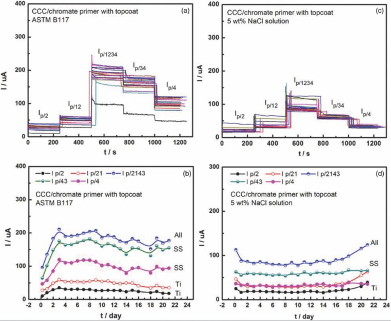
Figure 2. Anodic currents of panels connected with different fasteners during 3 weeks exposure to (a) B117 and (c) 5 wt% NaCl solution. The multiple curves in (a) and (c) represent measurements made at different times from 0.25 to 21 days. Currents as function of time during exposure in (b) B117 and (d) 5 wt% NaCl solution. #1 and #2 are Ti-6Al-4V fasteners; #3 and #4 are SS316 fasteners.
Fig. 2 also indicates that galvanic currents in B117 were larger than in 5 wt% NaCl bulk solution. ASTM B117 was performed at 35°C whereas the bulk electrolyte immersion was at RT. The solubility of oxygen decreases with increasing temperature, but the diffusivity of oxygen increases. Furthermore, the thin electrolyte layer present on the surface in ASTM B117 results in a smaller diffusion layer thickness. The cumulative effect of these differences was that the cathodic currents of the fasteners in ASTM B117, and thus the measured galvanic current, were larger than for immersion in NaCl solution of the same nominal composition. It should be noted that, because the bulk solution was not refreshed during the exposure, its aggressiveness could have decreased owing to leaching of chromate from the coatings.
The galvanic currents between each individual fastener and the panel coupled to all the other fasteners were monitored over time to determine the galvanic current from each fastener, as shown in Fig. 3. The currents from the SS316 fasteners, Ip124/3 and Ip123/4 (around 70 μA) were higher than those from Ti alloy fasteners, Ip234/1 and Ip134/2 (around 18 μA) in both environments. The cathodic currents of SS316 fasteners in B117 (around 70 μA) were much higher than those in 5 wt% NaCl solution (around 30 μA), whereas the cathodic currents of Ti alloy fasteners were approximately the same in the two environments. Moreover, the currents of fasteners at scribes (Ip134/2 and Ip123/4) were usually a little higher than at holes without scribes (Ip234/1 and Ip124/3), due to the ohmic drop between the fastener and the exposed Al alloy.
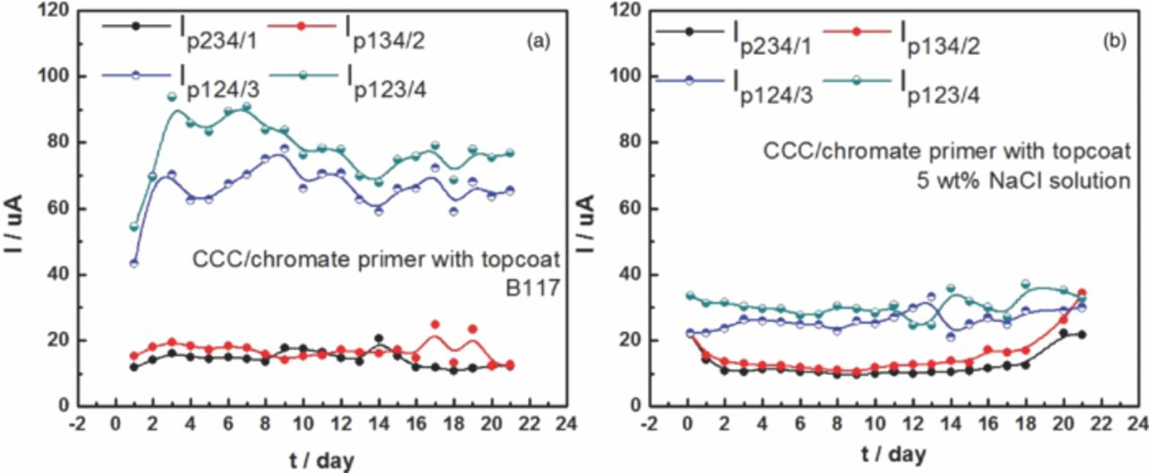
Figure 3. Cathodic currents of each fastener during 3 weeks exposure to B117 (a) and 5 wt% NaCl solution (b). #1 and #2 are Ti-6Al-4 V fasteners; #3 and #4 are SS316 fasteners.
Fig. 4 shows optical profilometry analysis of the corrosion attack caused by SS316 and Ti alloy fasteners after 3 weeks exposure in ASTM B117. It is clear that the SS316 fastener caused more corrosion than the Ti fastener for the two different coating systems, which is consistent with the galvanic current results. Comparison of the two coating systems indicates that the attack in the CCC/chromate primer/topcoat sample was deeper, but it was much wider in the adhesion promoter/Pr primer/topcoat sample. This difference could be caused by the different surface pretreatments of these two coating systems: chromate conversion coating and adhesion promoter, respectively.
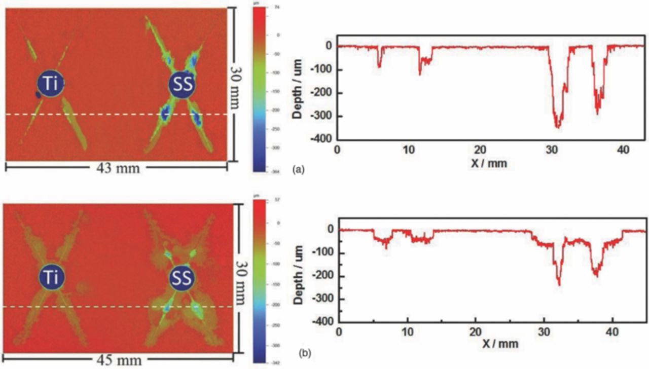
Figure 4. Topographic maps and linescans of two different coating systems after 3 weeks exposure in ASTM B117. A Ti fastener was on the left and a SS316 fastener on the right. a: CCC/chromate primer with topcoat. b: Adhesion promoter/Pr primer with topcoat.
Because SS316 and other stainless steel fasteners and inserts provide more galvanic acceleration and typically cause more corrosion damage on actual aircraft than titanium alloy fasteners and inserts,9,10 they create a more difficult challenge for protective coatings. Therefore, Al alloy panels with only SS316 fasteners were used in the following exposure tests. Fig. 5 shows anodic currents of panels with two different coatings during 3 weeks of exposure in B117 and 5 wt% NaCl bulk solution. The error bars are from two or three individual experiments. There was very little difference between the primer-only (Fig. 5a) and topcoated (Fig. 5b) samples as the topcoat had essentially no effect on the galvanic interaction of the fasteners and Al alloy exposed at the through-scribe. The anodic currents of adhesion promoter/Pr primer samples were higher than those of CCC/chromate primer samples in both environments, indicating that CCC/chromate primer samples had better performance on coated Al alloy panels than adhesion promoter/Pr primer samples. As shown previously, anodic currents of panels in ASTM B117 were higher than that in 5 wt% bulk NaCl solution, which indicates that ASTM B117 exposure is a more accelerated method for rapid coating assessment than full immersion in NaCl solution. From Faraday's law, the integral of anodic current over time can be used to determine an effective mass loss that reflects the extent of corrosion attack, which will be discussed in the following.
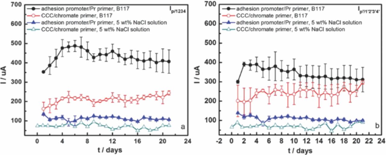
Figure 5. Anodic current of AA7075-T6 panel with different coating systems during three weeks exposure in two environments. Panels were coupling with only SS316 fasteners. Error bars are standard deviation from experiments that were repeated 2 or 3 times. a: Primer-only panels. b: Primer and topcoat panels.
Cathodic currents flowing out of each SS316 fastener contributed to the anodic current flowing into the panel. To assess the contribution of each fastener, cathodic currents of fasteners were measured in ASTM B117 and 5 wt% NaCl bulk solution by using one fastener as the working electrode and other fasteners and the panel physically contacted to each other as the other electrode, as shown in Fig. 6. Every fastener had the same current order: adhesion promoter/Pr primer sample in ASTM B117 > CCC/chromate primer sample in ASTM B117 > adhesion promoter/Pr primer sample in bulk solution > CCC/chromate primer sample in bulk solution, which was the same order found for the anodic currents shown in Fig. 5. The cathodic currents flowing from fasteners at scribed holes (Ip134/2 and Ip123/4) in ASTM B117 were a little higher than those at unscribed holes due to the ohmic drop, which is consistent with the results in Fig. 3 for the mixed fastener samples. The sum of the net cathodic currents of all fasteners should be equal to the net anodic current of the panel. Fig. 7 shows that in fact the sum of cathodic currents from the fasteners was quite close to the anodic current to the panel for the two different coatings at every daily measurement during 3 weeks exposure in B117.
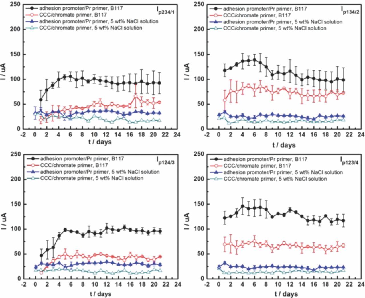
Figure 6. Cathodic current of each fastener of different coatings on panels with four SS316 fasteners. Error bars are standard deviation from experiments that were repeated 2 or 3 times.
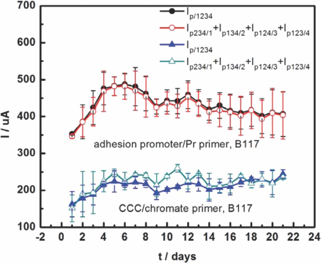
Figure 7. Anodic current of AA7075-T6 panel with different coatings and total cathodic current of corresponding fasteners. Error bars are standard deviation from experiments that were repeated 2 or 3 times.
Fig. 8 displays optical images and the surface morphology of scribes for CCC/chromate primer samples with or without topcoat after 3 weeks exposure in B117. At the top-left in Fig. 8 is the image just after the sample was taken out from the salt fog chamber and the top-right image is after the coatings were removed using concentrated nitric acid. The bottom images in Fig. 8 show the 2-D topographic maps of scribes in primed-only and topcoated samples. The adhesion promoter/Pr primer samples are shown in Fig. 9. As shown above for samples containing a mixture of SS316 and Ti alloy fasteners, these two coating systems had very different corrosion responses after 3 weeks in B117. The CCC/chromate primer sample exhibited no obvious blisters on the samples and the Al alloy corrosion only occurred at the scribes but went into the substrate very deeply. The deepest attack was 380–400 μm, but the width of corroded areas was only 1–3 mm, as shown in Fig. 10. The original width of scribe was around 400 μm, which was the diameter of the scribe tool tip. The adhesion promoter/Pr primer sample exhibited many large blisters. Attack occurred not just at scribes, but also around unscribed fasteners and even on some spots far away from fasteners and scribes. The OP images indicate that corrosion spread out very widely from the scribes and unscribed holes along the coating/substrate interface but did not penetrate deeply into the substrate. It should be noticed that blisters around unscribed fasteners in Fig. 9 only appeared on the primed-only sample, with no attack at unscribed fasteners on the topcoated sample. This was replicated in the repeat experiments.
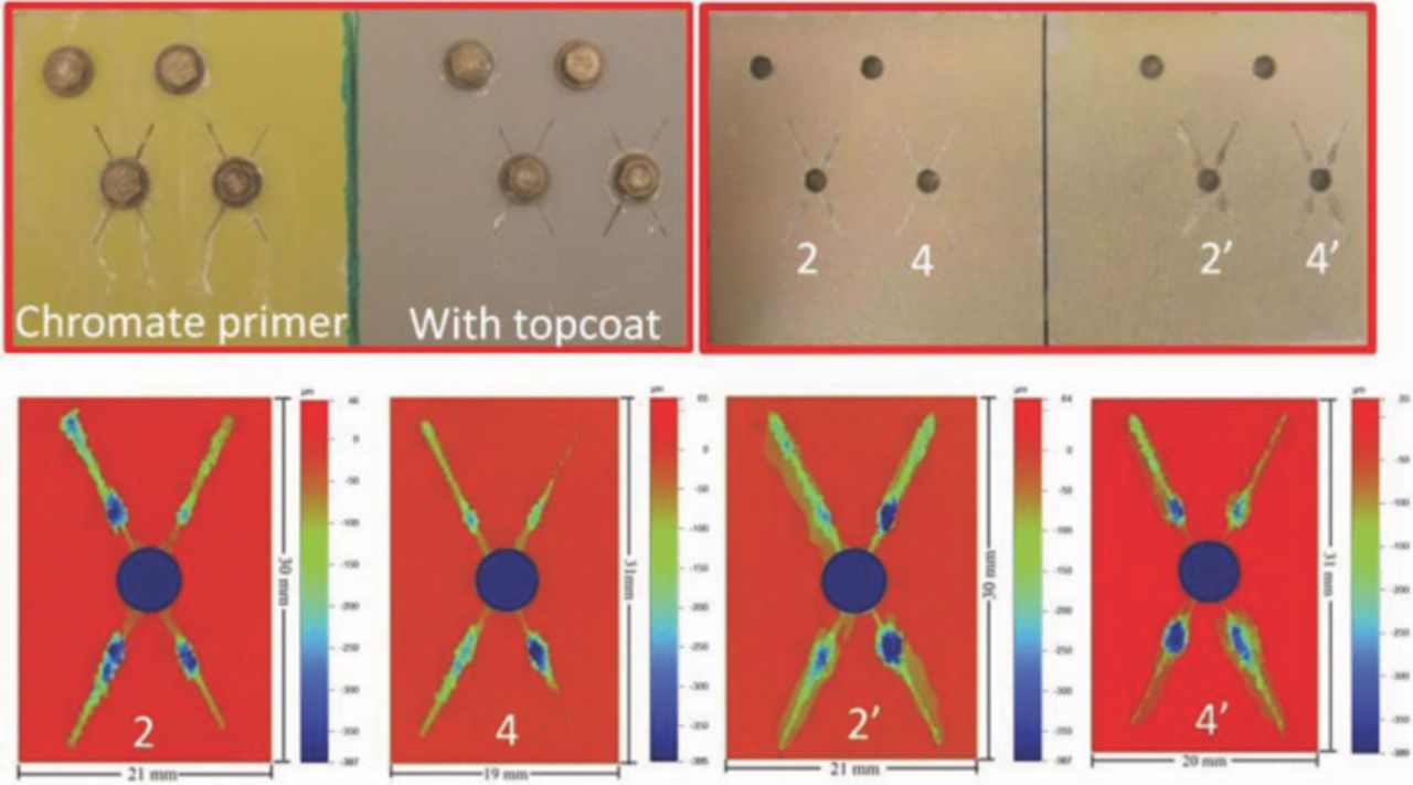
Figure 8. Surface morphology of CCC/chromate primer samples with or without topcoat after 3 weeks exposure in B117. Top-right is the image after removing coatings by nitric acid.
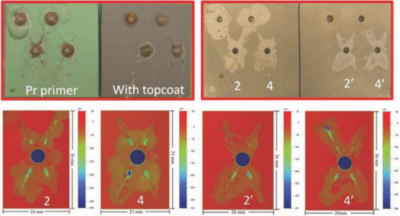
Figure 9. Surface morphology of adhesion promoter/Pr primer samples with or without topcoat after 3 weeks exposure in B117. Top-right is the image after removing coatings by nitric acid.
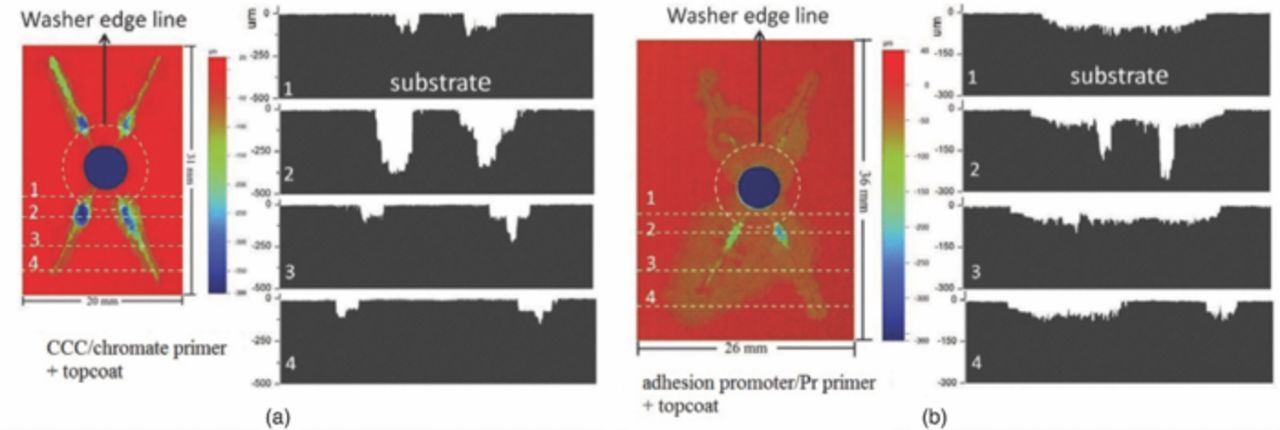
Figure 10. Topographic maps and depth cross sections at different distances from fastener. The circular dashed line represents the washer edge. a: CCC/chromate/with topcoat. b: adhesion promoter/Pr primer/with topcoat.
Discussion
ASTM B117 and 5 wt% NaCl bulk solution are different environments even though they have the same NaCl concentration. Much corrosion and protection work of metals has been performed on samples immersed in bulk electrolyte because full immersion is a relatively stable condition and is easily controlled in the lab. However, the field environment for many metals, in particular high strength Al alloys, is atmospheric exposure in which the sample surface is covered with an adsorbed moisture layer in equilibrium with humid air, droplets of spray, condensation, or precipitation. Such atmospheric environments can influence the initiation and growth of various forms of corrosion by changing local aggressiveness and the solution resistance between active anodes and cathodes. The ASTM B117 salt fog chamber does not replicate most atmospheric corrosion environments. Nonetheless, the comparison of corrosion behavior in B117 with the behavior in bulk solution of the same composition is of interest because of the differences in the two conditions. The electrolyte layer in ASTM B117 is very thin and not uniform or stable owing to droplet initiation, growth, agglomeration, sliding down, falling off, etc. which are phenomena that occur in real environments. In this work the temperature in the B117 chamber was about 35°C which was higher than the room temperature of the full immersion tests. The higher temperature and thinner electrolyte layer in B117 accelerated the cathodic reaction on fasteners causing more corrosion attack on Al alloy panel than in bulk solution. This explains why galvanic currents in ASTM B117 were higher than in bulk solution in Fig. 2, 3, 5 and 6. However, as mentioned above, the bulk solutions used in these experiments might have become less aggressive over time because of release of inhibitors from the coatings.
In the same environment, the cathodic current density associated with oxygen reduction in the mass transport controlled range should be the same on different electrode surfaces because the limiting current density theoretically only depends on the dissolved oxygen concentration, diffusivity, and oxygen diffusion layer thickness. However, this is only true for ideal electronic conductors.24 In the present work, Ti alloy and SS316 fasteners both have a layer of oxide film on the surface, TiO2 and Cr2O3 respectively, which can be diffusion barriers for oxygen and interfere with electron charge transfer reactions.24 Differences in these oxides result in the SS316 fasteners providing more cathodic current than Ti alloy fasteners and therefore more corrosion attack on scribed areas as shown in Fig. 4, even though the potential difference of SS316 and aluminum alloys is close to that of Ti-6Al-4V and aluminum alloys.9,23 Cathodic polarization curves for samples immersed in 5 wt% NaCl bulk solution also showed that the current of a SS316 fastener was higher than a Ti-6Al-4V fastener.9
Coatings protect the underlying substrate because they prevent access of the electrolyte and oxygen to the surface and in some cases release chemical inhibitors to reduce corrosion attack. In an aggressive environment, a protective coating should minimize attack at any defect in the coating, such as the scribes intentionally added to the samples in this work, and adhere well to the edge of the defect to prevent the attack from propagating underneath, so-called scribe creep. A direct comparison of the two coating systems studied in this work is seen in Fig. 10, which shows topographic maps and cross sections from optical profilometry after 3 weeks of B117 exposure. It shows the depth profiles at different distances from a fastener. The white areas below the zero line represent the corroded volume. For both coating systems the scribe attack extended horizontally and vertically. For the CCC/chromate primer system the attack broadened and deepened only at selective sites. It should be noted that optical profilometry is a top-down line-of-sight method. Therefore, any attack that might have propagated horizontally at a depth to result in undercutting would not be detected. This is a source of error, particularly for wrought Al alloy samples that might exhibit intergranular or selective grain attack along the working direction.25,26 Nonetheless, the small amount of horizontal broadening of the attack indicates the good adhesion and protection provided by the coating system.
The wider corroded areas in the adhesion promoter/Pr primer sample indicate that the interface was not resistant to penetration by the electrolyte. A few sites in this sample also exhibited deep attack, but it was not as deep as in the CCC/chromate primer sample and the average depth of penetration was much less. Even though the samples with these two coatings exhibited very different corrosion morphologies, the corroded volumes, which can be calculated by the integral across the sample of the area under the zero line, were similar in magnitude. Note that the holes in the panels were not considered in the data analysis. The adhesion promoter/Pr primer sample should have larger substrate corrosion volume than CCC/chromate primer sample, because larger anodic currents flowed into the promoter/Pr primer panel, as shown in Fig. 5. Moreover, the local electrolyte at the substrate/coating interface probably had different compositions for these two coatings, even though they were exposed to the same environment, because soluble chromate or Pr ions can be released from the coatings, migrate to defects or corrosion sites and inhibit further damage.27–31 The chromate released from the CCC/chromate primer sample was one reason why corrosion attack did not propagate widely in CCC/chromate primer sample.
In the present work, current distribution on the fastener/panel structure involved cathodic currents that flowed from each fastener into the exposed substrate to create anodic current at the scribes. Therefore, the anodic current of the panel had to be balanced by the total cathodic current of the fasteners, as shown in Fig. 7. However, the local anodic current density along the scribes and under the coating varied considerably, partly because the resistance between the cathodes (fasteners) and local anode sites increased with the distance between them. Sites more distant from fasteners should have less attack because of the higher resistance. There will be no effect of galvanic corrosion if the distance between fastener and expose site is too far, which has been shown previously for fasteners far from the scribe.10 The corrosion profiles at lines 2 to 4 in Fig. 10 show that corroded area and depth decreased with distance away from the fastener due to the increasing resistance between fastener and exposed sites. The corroded areas at line 1 were underneath a 10 mm diameter washer, where crevice corrosion occurred. The scribe regions below the fastener had more corrosion attack than the scribe region above the fasteners in Fig. 8 and 9, probably because of the effect of gravity on the concentrated solutions created by the corrosion reactions.
The goal of this work was to quantify the extent of accelerated corrosion testing of coated Al alloy panels. Two different approaches that were previously introduced to calculate the effective mass loss under the coatings,10 galvanic charge and OP analysis of the scribed area, were also used in the present work. In short, the volume loss determined from OP analysis and integration of the galvanic charge data can both be converted to an equivalent mass loss. Fig. 11 shows the equivalent mass loss of panels with different coating systems after 3 weeks ASTM B117 exposure. The mass loss of adhesion promoter/Pr primer samples was larger than that of CCC/chromate primer, which is consistent with the current measurement in Fig. 5 and morphology results in Fig. 8 and 9. Similarly, when comparing with effects of different type fasteners in chromate primer/CCC sample, it can be seen that coupling with SS316 fasteners caused more mass loss than with Ti alloy fasteners, which is also consistent with the results in Fig. 2–4.
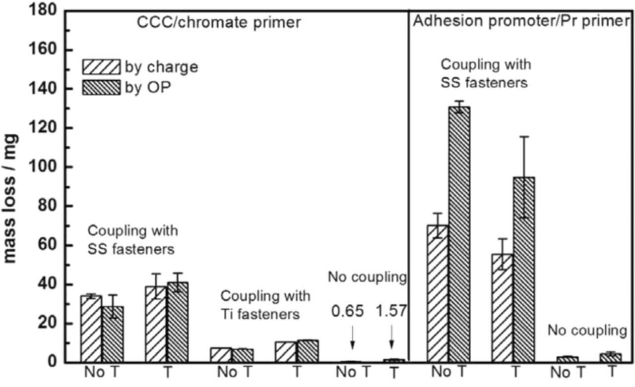
Figure 11. Equivalent mass loss of panels with different coating systems after 3 weeks B117 exposure measured by galvanic charge and OP analysis. "T" in the X axis labels means topcoat. The error bars are from two or three individual experiments.
The equivalent mass loss determined by each of the two methods might contain errors that would underestimate the extent of attack. The optical profilometry measurements might not sense attack that undercut the metal surface so the measured lost volume and mass might be less than the actual amounts. The sample with chromate primer and topcoat was sectioned through a spot of deep attack. An undercut region was observed, and it was estimated that the area not observable from above by the line-of-sight OP method was less than 12% of the total area at the plane of sectioning. Another section on the same sample indicated no undercut at all. The galvanic charge measurements might also underestimate the extent of attack because the actual anodic current from a scribe might be only partially consumed by cathodic reactions at distant fasteners. Local hydrogen evolution always accompanies pitting corrosion of Al, and the amount of local cathodic reaction has been estimated to be about 15%.32 The equivalent mass loss for the two methods were quite similar for the samples with SS316 fasteners, which suggests that the errors in the two measurements were either both small or similar in magnitude. For the adhesion promoter/Pr primer samples, the values of equivalent mass determined from the galvanic charge were significantly less than those determined from optical profilometry. The attack along the coating/substrate interface in this case was likely accompanied by a larger extent of local cathodic reaction occurring under the coating rather than at the distant fasteners. This "self corrosion" was not sensed by the galvanic current so that the equivalent mass determined from the galvanic charge was erroneously low.
Also shown in Fig. 11 are values of equivalent mass loss determined by optical profilometry for scribed samples that had no fasteners in the holes. Galvanic charge measurements were of course not possible for these samples. However, the analysis of the last paragraph suggests that the mass loss determined by optical profilometry should be rather accurate, which allows comparison of values for samples with and without fasteners. The acceleration factor (AF) describing the effect of galvanic coupling on the rate of attack can be defined by:
![Equation ([1])](https://content.cld.iop.org/journals/1945-7111/161/1/C42/revision1/jes_161_1_C42eqn1.jpg)
where mc and mnc are the equivalent mass loss values for samples with coupling and with no coupling, respectively. The acceleration factors for SS316 fasteners were calculated to be 43 and 21 for adhesion promoter/Pr primer samples without and with topcoat, respectively, and 48 and 26 for CCC/chromate primer samples without and with topcoat, respectively. The mass loss values of non-galvanic chromate panels were very small, as shown in Fig. 11, which creates a lot of error in the calculated AF values. For example, the volume change calculated for the non-galvanic chromate sample was 1.77 ± 0.10 mm3 where the standard deviation was determined by multiple analyzes of the sample. The volume change for the scribed control sample was 1.52 ± 0.19 mm3. The difference in average values multiplied by 2.7 mg/mm3 resulted in the plotted mass change of 0.65 mg. The error in this number can be considered to be the sum of the standard deviations of the two measurements, or 0.78 mg, which is as large as the reported mass change value. Because the average mass change for the non-galvanic sample is the denominator in Eq. 1, the error in the reported AF is large. It should be noted that the volume changes for the chromate sample with topcoat and for the adhesion promoter/Pr primer samples were relatively large so the errors are much less. Despite this error, it is quite interesting that the acceleration factors describing the effects of SS316 fasteners were similar for the two different coating systems that had very different attack morphology. This similarity is because the available cathodic current from these fasteners was the same, regardless of the coating system. The cumulative galvanic attack was clearly dependent on the available cathodic current. The adhesion promoter/Pr primer samples with topcoat and SS316 fasteners exhibited less attack than those without topcoat, whereas this effect of the topcoat was not observed for the CCC/chromate primer samples. As shown in Figure 9, blisters formed around the SS316 fasteners at unscribed holes for adhesion promoter/Pr primer samples without topcoat, but not at the same fasteners when the samples had a topcoat. The adhesion promoter did not passivate the Al alloy surface and galvanic coupling could occur through the primer without the topcoat in the absence of a scribe. In contrast, CCC passivated the Al alloy surface and provided protection even without a topcoat.
The analysis also shows that the acceleration factors for SS316 fasteners were higher than those for Ti alloy fasteners (A = 12 and 7 for without and with topcoat, respectively). As shown previously9,10 and above, SS316 fasteners provide higher cathodic current and accelerate more galvanic corrosion attack. The effect of Ti alloy fasteners was only determined for the CCC/chromate primer system as experiments with Ti alloy fasteners in the other coating system were not performed. The two methods for assessing equivalent mass loss were also quite reproducible for the Ti alloy fasteners in the chromate coating system.
Conclusions
Effects of different type fasteners on accelerated corrosion test panels for coated Al alloy were compared. Galvanic corrosion in ASTM B117 and in 5 wt% NaCl bulk solution was also compared. Moreover, mass loss by charge and optical profilometry analysis was calculated to quantitatively to characterize the accelerated corrosion extent on two different coatings. Specific conclusions are as following:
- (1)The galvanic current measured with SS316 fasteners was higher than with Ti fasteners because of differences in cathodic current each alloy provides.
- (2)Galvanic current in ASTM B117 was larger than that in 5 wt% NaCl bulk solution, because of higher temperature, thinner electrolyte layer and greater availability of oxygen in B117.
- (3)Corrosion degradation of two different coating systems was compared. CCC/Chromate primer panels exhibited deeper corrosion near scribes; while adhesion promoter/Pr primer samples showed relative wider corrosion. This difference was most likely from the different pretreatments due to their different ability to passivate the aluminum substrate.
- (4)An approach was developed to determine acceleration factor that describes influence of galvanic coupling between fastener and substrate to accelerate coating degradation relative to situation with no galvanic coupling. The acceleration factors for SS316 fasteners were estimated to be 45 and 25 for coating systems without and with a topcoat, respectively. The acceleration factors for Ti alloy fasteners were smaller, 12 and 7 for samples without and with a topcoat, respectively.
Acknowledgment
This work was supported by Office of the Secretary of Defense Technical Corrosion Collaboration through the US Air Force Academy.