
Abstract
In order to confirm reasons that deteriorate cathode performances, Ni-rich Li[Ni0.7Mn0.3]O2 is modified by lithium isopropoxide to artificially provide lithium excess environment by forming Li2O on the surface of active materials. X-ray diffraction patterns indicate that the lithium oxide coating does not affect structural change comparing to the bare material. Scanning electron microscopy and transmission electron microscopy data show the presence of coating layers on the surface of Li[Ni0.7Mn0.3]O2. Electrochemical tests demonstrate that the Li2O-coated Li[Ni0.7Mn0.3]O2 exhibits a greater irreversible capacity with a small capacity because of the presence of insulating layers composed of lithium compounds on the active materials since these layers delay facile Li+ diffusion. Also, the Li2O layer forms byproducts such as Li2CO3, LiOH, and LiF, as are proved by X-ray photoelectron spectroscopy and time-of-flight secondary ion mass spectrometry. The presence of residual lithium tends to bond with hydrocarbons induced from decomposition of electrolytic salt during electrochemical reactions. And the reaction, accelerated by the decomposition of electrolytic salt that produces the byproducts, causes the formation of passive layers on the surface of active material. As a result, the new layers consequently impede diffusion of lithium ions that deteriorate electrochemical properties.
Export citation and abstract BibTeX RIS
Rechargeable lithium batteries (LIBs) have been intensively investigated as power-assisting or power sources in automotive applications such as electric vehicles, hybrid electric vehicles, and plug-in hybrid electric vehicles. Furthermore, rechargeable LIBs are considered to be the most promising energy storage system for renewable energy systems operating on intermittent energy sources, such as wind power plants and solar cells because of their high energy density and long cycle life. These kinds of applications require high capacity, good capacity retention, and reliable safety. For these reasons, LiCoO2 is not suitable due to lower capacity and structural instability caused by hexagonal to monoclinic structural change which results in Co dissolution.1–3 Therefore, Ni-rich layered compounds (Li[Ni1-xMnx]O2) are very attractive in terms of capacity and its retention upon cycling.4–6 Unlike LiCoO2, however, control of cationic stoichiometry, namely Li/Ni ratio to be one, is difficult, particularly in the Li layer of [Li1-xNiIIx]3b[NiIII]3a[O2]6c.7–10 To overcome this drawback, Arai et al.11 suggested that addition of excessive lithium is effective in reduction of cation mixing in the Li layer. The resulting structure retains the well-ordered layer structure with low cation mixing, so that the materials could deliver better capacity upon cycling. Since the excessive amount of lithium is necessary to produce highly ordered structure for Ni-rich layer compounds, unreacted lithium ingredient can be remained on the surface of active materials, presumably as an oxide form, Li2O. Also, the outer part of the Li2O is contaminated with moisture and CO2 in air, forming LiOH and Li2CO3.
For the aforementioned reasons, Ni-rich compounds usually exhibit highly alkaline state above pH 11 owing to the remained lithium salts, when they are stabilized into the α-NaFeO2 layer structure. The presence of residual lithium compounds may not be favored because they cause side reactions through oxidative decomposition of LiOH and Li2CO3 at high voltage. This reaction is not reversible, causing irreversible capacity. In this paper, we adopt Co-free Li[Ni0.7Mn0.3]O2 cathode material so as to eliminate the effect of Co on capacity that accelerates capacity fade due to dissolution of Co ions into the electrolyte.12 Here, the as-synthesized Li[Ni0.7Mn0.3]O2 is modified by Li2O to intentionally provide lithium-rich environment in the outer surface. Also, we investigate how the residual lithium compounds deteriorate the electrode performance during cycling.
Experimental
First, (Ni0.7Mn0.3)(OH)2 precursor was prepared via co-precipitation following our prior works.13 An aqueous solution of Ni(II)SO4·6H2O (Samchun) and Mn(II)SO4·5H2O (Junsei) (molar ratio of Ni:Mn = 7:3) with concentration of 2.0 mol L−1 was dropped into a continuously stirred tank reactor (CSTR) with 1000 rpm under N2 atmosphere. At the same time, NaOH solution (2.0 mol L−1) and NH4OH solution (3.6 mol L−1) as chelating agents were also separately added into the reactor by adjusting the solution pH to 11.7 at 50°C. Then, the precipitated particles were filtered, washed, and dried in an oven at 80°C for 24 h. The obtained (Ni0.7Mn0.3)(OH)2 was heated to produce dehydrated (Ni0.7Mn0.3)3O4 at 500°C for 5 h. The dehydrates were thoroughly mixed with an appropriate amount of LiOH and calcined at 900°C for 15 h in air.
To prepare the environment in which the as-synthesized active materials present with residual lithium compounds, the surfaces of active materials were intentionally modified by excess amount of lithium isopropoxide; for 10 g of active material, the added amount of lithium isopropoxide is 0.7 g, which corresponds to ∼0.01 mol of lithium isopropoxide. According to our preliminary experiment, addition of more lithium isopropoxide resulted in low capacity due to the thick coating layer and less amount of lithium isopropoxide below 0.007 mol did not show the presence of uniform Li2O coating layer. Lithium isopropoxide was dissolved in anhydrous ethanol, and the as-synthesized Li[Ni0.7Mn0.3]O2 was poured into the solution and stirred until the solution completed evaporation of the solvent at 80°C in air. Finally, the dried powder was heated at 400°C for 5 h in air to form lithium oxide (approximately 0.0045 mol per 1 mol Li[Ni0.7Mn0.3]O2 active material) on the surface of active materials.
X-ray diffractometry (XRD; Rint-2000, Rigaku) and transmission electron microscopy (HR-TEM; JEM-3010, JEOL) were employed to characterize the synthesized powders. Time-of-flight secondary ion mass spectroscopy (ToF-SIMS; PHI TRIFT V, ULVAC-PHI) was also used to confirm the presence of the lithium oxide layer on the surface of Li[Ni0.7Mn0.3]O2 powders. Also, X-ray photoelectron spectroscopy (XPS; PHI 5600, Perkin-Elmer) measurements were conducted on the surfaces of bare and coated Li[Ni0.7Mn0.3]O2 materials. Macro-mode (3 mm × 3 mm) Ar-ion etching was done to analyze the chemical state and surface composition of the coated powders. The etching rate was estimated as 4 Å min−1 for silica.
For the fabrication of cathodes, the as-synthesized and the Li2O-coated Li[Ni0.7Mn0.3]O2 powders were mixed with conductive materials (Super-P and Ketjen black, 1:1 in weight) and polyvinylidene fluoride in a weight ratio of 8:1:1 in N-methyl-2-pyrrolidone. The obtained slurries were applied onto Al foil and dried at 80°C in air. The electrodes were transferred to a vacuum oven and dried at 110°C overnight prior to use. Coin-type cells (2032) were assembled using Li metal (Honjo chemical) as the anode in an argon-filled glove box. The electrolyte used was 1M LiPF6 in ethyl carbonate–dimethyl carbonate (3:7 in volume, PanaX). The cells were charged and discharged between 3.0 and 4.3 V by applying a constant current (50 mA g−1) for electrochemical tests at room temperature.
In situ XRD data were obtained using an Empyrean diffractometer (PANalytical) equipped with monochromated Cu Kα radiation from 2θ = 15 to 70°, with a step size of 0.03° and a count time of 7s using a lab-made in situ cell.14 The cell was charged and discharged with a current density of 50 mA g−1. The lattice parameters were calculated by the following method: the positions of the individual peaks were fitted with a psuedo-Voigt or Lorentz function, and typically 8 or 9 peak positions were input to fit the program which minimizes the least squares difference between the calculated and measured peak positions by adjusting the lattice constant and the vertical displacement of the sample.
To identify the presence of byproducts on the surface of the active materials after cycling, the cycled active materials were measured using a ToF-SIMS surface analyzer operated at 10−9 Torr, equipped with a liquid Bi+ ion source and pulse electron flooding. During the analysis, the targets were bombarded by the 10 keV Bi+ beams with a pulsed primary ion current varying from 0.3 to 0.5 pA. The total collection time was 100s and rastered over a 120 μm × 120 μm dimension.
Results and Discussion
Figure 1 shows Rietveld refinement results of bare and lithium oxide-coated Li[Ni0.7Mn0.3]O2 (approximately 0.0045 mole per 1 mole Li[Ni0.7Mn0.3]O2 active material). The XRD patterns could be identified as an α-NaFeO2 structure with  space group. Though the Li[Ni0.7Mn0.3]O2 was modified by foreign layers, there are no significant differences in the XRD pattern compared to that of the bare Li[Ni0.7Mn0.3]O2. The calculated lattice parameters also indicate no change in the crystal structure before and after the coating (Tables I and II). The amount of Ni2+ occupying Li site (3b), due to the similarity of ionic radius for Li+ (0.76 Å, coordination number: 6)15 and Ni2+ (0.69 Å, coordination number: 6)15 appears to be identical for both materials, approximately 5.9% in Li site, resulting in [Li0.941Ni0.059][Ni0.7Mn0.3]O2. This is reasonable that the coating layer is comprised of low crystalline product since the heating temperature of 400°C is too low to form crystalline phase but sufficient to remove isopropoxide ingredient, resulting in formation of low crystalline Li2O coating layer. And it is also thought that the lithium oxide does incorporate into neither Li nor Ni site because of no change in the lattice parameters (Tables I and II) but resides only on the surface of the active materials. For convenience, in the following discussion, the phases are still associated with their nominal chemical formula Li[Ni0.7Mn0.3]O2, whatever the real cationic distribution.
Table I. Rietveld refinement results of XRD data for bare Li[Ni0.7Mn0.3]O2.
| Nominal Formula | Li[Ni0.7Mn0.3]O2 | |||||
|---|---|---|---|---|---|---|
| Crystal system | Rhombohedral | |||||
| Space group |  | |||||
| Atom | Site | x | y | z | g | B #x002F; Å2 |
| Li | 3a | 0 | 0 | 1/2 | 0.941(2) | 1.1 |
| Ni2 | 3a | 0 | 0 | 1/2 | 0.059(2) | 1.1 |
| Ni1 | 3b | 0 | 0 | 0 | 0.7 | 1.0 |
| Mn | 3b | 0 | 0 | 0 | 0.3 | 1.0 |
| O | 6c | 0 | 0 | 0.258(3) | 1 | 0.8 |
| a-axis / Å | 2.8804(2) | |||||
| c-axis / Å | 14.2543(10) | |||||
| Rwp /% | 14.2 | |||||
| Rp /% | 9.15 | |||||
Table II. Rietveld refinement results of XRD data for Li2O-coated Li[Ni0.7Mn0.3]O2.
| Nominal Formula | Li[Ni0.7Mn0.3]O2 | |||||
|---|---|---|---|---|---|---|
| Crystal system | Rhombohedral | |||||
| Space group |  | |||||
| Atom | Site | x | y | z | g | B / Å2 |
| Li1 | 3a | 0 | 0 | 1/2 | 0.941 | 1.1 |
| Ni2 | 3a | 0 | 0 | 1/2 | 0.059(2) | 1.1 |
| Ni1 | 3b | 0 | 0 | 0 | 0.7 | 1.0 |
| Mn | 3b | 0 | 0 | 0 | 0.3 | 1.0 |
| O | 6c | 0 | 0 | 0.258(2) | 1 | 0.8 |
| a-axis / Å | 2.8808(2) | |||||
| c-axis / Å | 14.2548(9) | |||||
| Rwp /% | 11.8 | |||||
| Rp /% | 7.46 | |||||
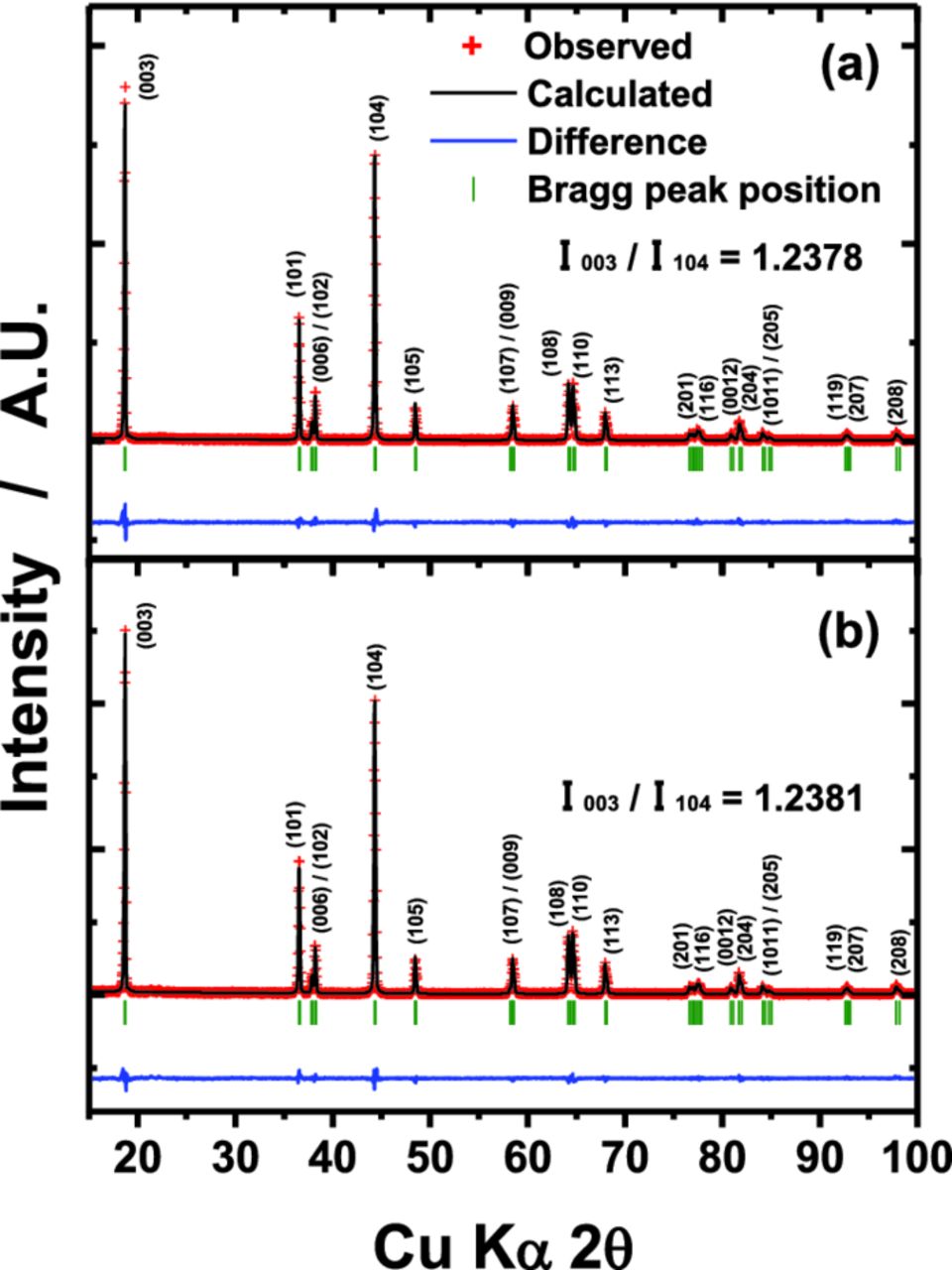
Figure 1. Rietveld refinement results of XRD data for (a) bare and (b) Li2O-coated Li[Ni0.7Mn0.3]O2 powder.
To confirm morphology of the as-synthesized and the Li2O-coated coated materials, the powders were observed by SEM and TEM (Figure 2). In the SEM images (Figs. 2a and 2b), the smooth surface of active materials (Fig. 2a) is covered by flake-like particles after the Li2O coating (Fig. 2b). From TEM observation (Fig. 2c), even the bare materials display some sediment of foreign materials on the outer surface, presumably lithium compounds such as Li2O, Li2CO3 and LiOH derived from the excessive amount of LiOH addition for compensation of lithium evaporation to minimize the cation mixing during calcination. Such foreign layers are readily noticed on the surface of the active material after the Li2O coating (Fig. 2d); the newly formed thicker layers range from 10−40 nm in thickness for the Li[Ni0.7Mn0.3]O2, and the resulting coating layers appear inhomogeneous but porous showing light contrast compared to the active material.
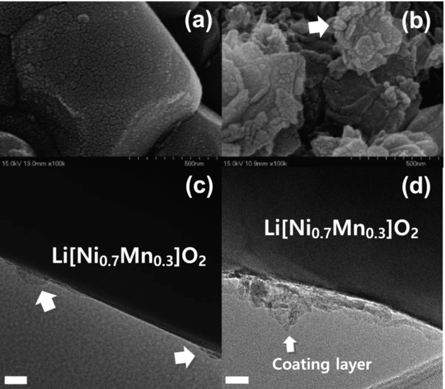
Figure 2. SEM images of the (a) bare and (b) Li2O-coated Li[Ni0.7Mn0.3]O2; bright-field TEM images the (c) bare and (d) Li2O-coated Li[Ni0.7Mn0.3]O2. The scale bar indicates 20 nm.
Residual lithium oxide, Li2O, on the surface of active materials is readily combined with oxygen, carbon dioxide, and water molecules, and forms compounds like LiOH and Li2CO3, as confirmed in ToF-SIMS spectra (Figs. 3a and 3b). In particular, the Li2O-coated sample represents stronger spectrum intensity for the Li2C+ (m = 31.01) and Li2OH+ (m = 31.03) fragments (Fig. 3b). The results indicate that the outer surface of Li2O coating layer was obviously transformed to LiOH and Li2CO3 layers after exposure in air. Hence, the bare and Li2O-coated materials were analyzed by pH, LiOH, and Li2CO3 titrations (Fig. 3c). In the result of pH titration, the coated material by Li2O exhibits higher pH value than that of the bare. And through the LiOH and Li2CO3 titrations, it is confirmed that the Li2O coating induces more formation of LiOH and, in particular, Li2CO3 on the surface of active materials (Scheme 1).
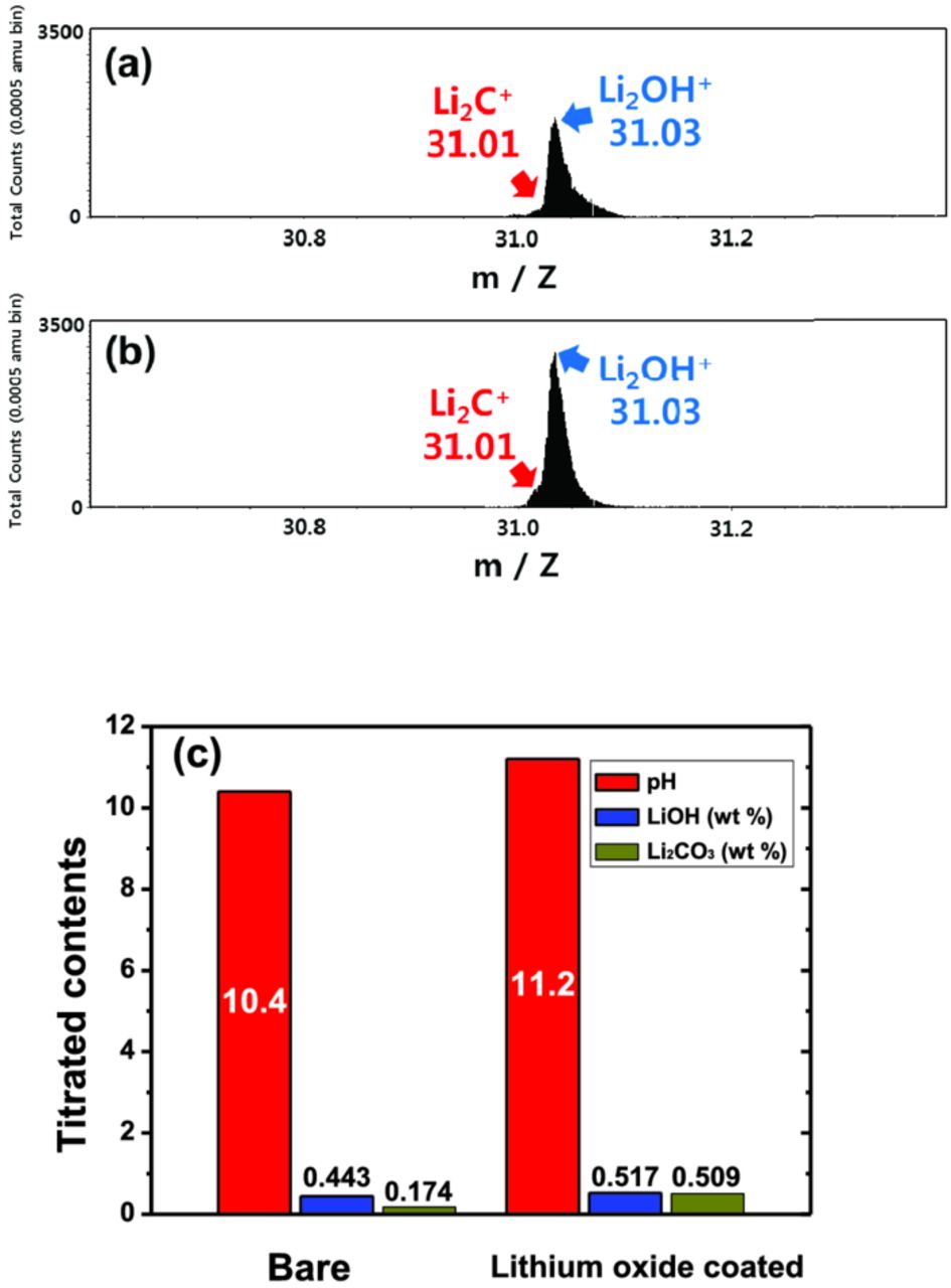
Figure 3. ToF-SIMS spectra for Li2OH+ and Li2C+ of (a) bare Li[Ni0.7Mn0.3]O2, (b) Li2O-coated Li[Ni0.7Mn0.3]O2 materials before cycling, and (c) pH measurement and titration results of LiOH and Li2CO3 using bare and Li2O-coated Li[Ni0.7Mn0.3]O2 powders before electrochemical test.
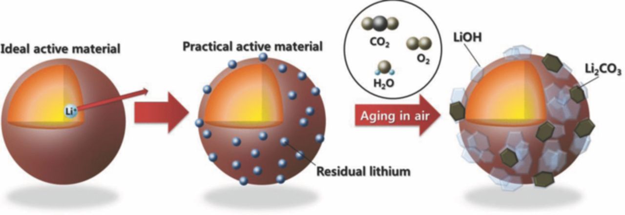
Scheme 1. Surface change of Li[Ni0.7Mn0.3]O2 materials after exposure in air.
The bare and the Li2O-coated Li[Ni0.7Mn0.3]O2/Li cells were continuously cycled at a constant current density of 50 mA g−1 at 25°C. The first discharge capacity of the bare material appears evidently higher than that of Li2O-coated electrode (Fig. 4a). In addition, the coulombic efficiency of the bare electrode at the first cycle is approximately 75.3%, whereas the coated material shows lower columbic efficiency (67.7%) than that of the bare. The presence of thick and non-uniform coating layers would cause lower discharge capacity and efficiency for the Li2O-coated Li[Ni0.7Mn0.3]O2 electrode. Decomposition or oxidation of those excessive lithium compounds derived from the Li2O coating is also considered for the low coulombic efficiency at the first cycle. The capacity retentions are approximately 76% for the bare and 70% for the Li2O-coated electrodes (Figs. 4b-4d).
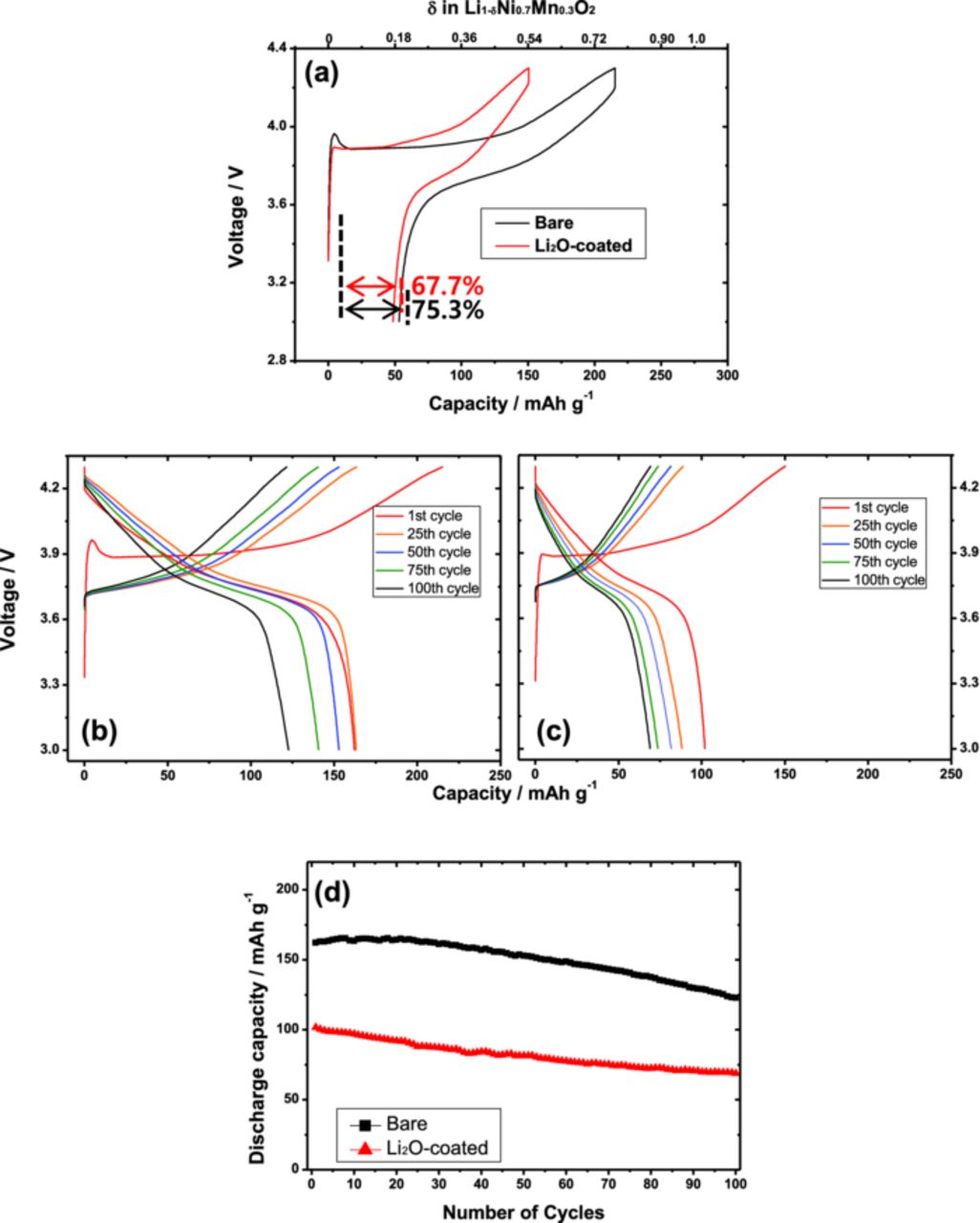
Figure 4. Charge and discharge curves of Li[Ni0.7Mn0.3]O2/Li cells at room temperature; (a) first charge-discharge curves of bare and Li2O-coated Li[Ni0.7Mn0.3]O2/Li cells; continuous charge and discharge curves of (b) bare, (c) Li2O-coated Li[Ni0.7Mn0.3]O2/Li cells; (d) cyclability plots of the cells at 50 mA g−1 at room temperature. The presented curves are for 1st, 25th, 50th, 75th, and 100th cycles.
As observed in Fig. 4, deterioration of the electrode performance is obvious in the virtual condition through the surface modification by residual lithium compounds. Since the only difference between two electrodes is the presence of residual lithium compounds on the surface of active materials, the remained lithium compounds may affect structural variation during Li+ insertion and extraction. Hence, the bare and Li2O-coated materials were examined by in situ XRD measurement to follow the structural changes during the first cycle (Fig. 5). In fact, both electrodes undergo similar structural evolution during the charge and discharge. Some peaks gradually shift toward higher angle in 2θ on charge that is due to structural changes from H1 (hexagonal) to H2 (hexagonal phase) phase via the intermediate M (monoclinic) phase.16–18 And the peaks return to the original peak position on discharge without appearance of other phases, occurring in a simple topotactic reaction (Figs. 5a and 5b).
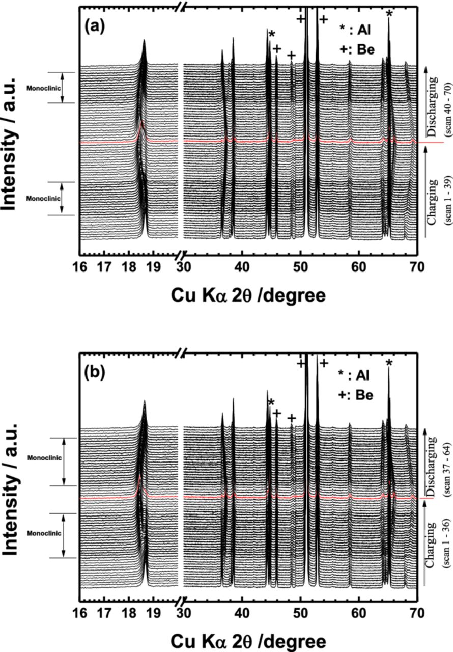
Figure 5. In-situ XRD patterns of (a) bare and (b) Li2O-coated Li[Ni0.7Mn0.3]O2 as a function of Li content during the first cycle. Al denotes an aluminum foil used as a current collector.
Interlayer distances were calculated from the in situ XRD data shown in Fig. 5, and the results are plotted in Fig. 6. The resulting distances increase gradually during the charge because of the increase in coulombic (electrostatic) repulsion force between the oxygen-oxygen layers by ionicity of metal-oxygen bonding.19 Although the delivered capacity was small for the Li2O-coated electrode, the interlayer distances vary similarly to those of the bare electrode. From this point of view, it is possible that the residual lithium compounds do not affect structural change but do interrupt Li+ diffusion because of the thickness and insulating properties the lithium compounds. For the reasons, the coated electrode would deliver less capacity than the bare material.
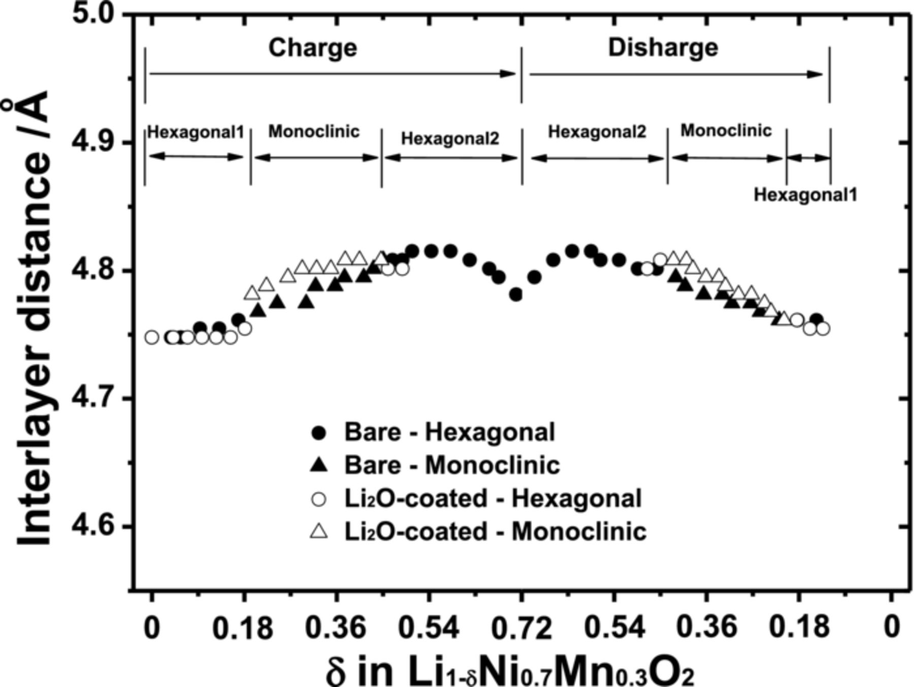
Figure 6. Interlayer distances derived from the (003) peak for the bare and the Li2O-coated Li[Ni0.7Mn0.3]O2 from the in-situ XRD patterns in Figure 5.
The extensively cycled cells were disassembled, and both the bare and Li2O-coated electrodes were washed with salt-free dimethyl carbonate solution and subsequently dried in vacuum oven at 80°C. In the TEM image of bare material, the sediments were, in part, detected on the surface of active material after the cycling, and the original smooth surface line of the particle was also kept (Fig. 7a). The coating layer on the surface of the coated material became thicker than before cycling (Fig. 7b). It is likely that the coated lithium compounds layers are altered through reaction with electrolyte during the cycling.
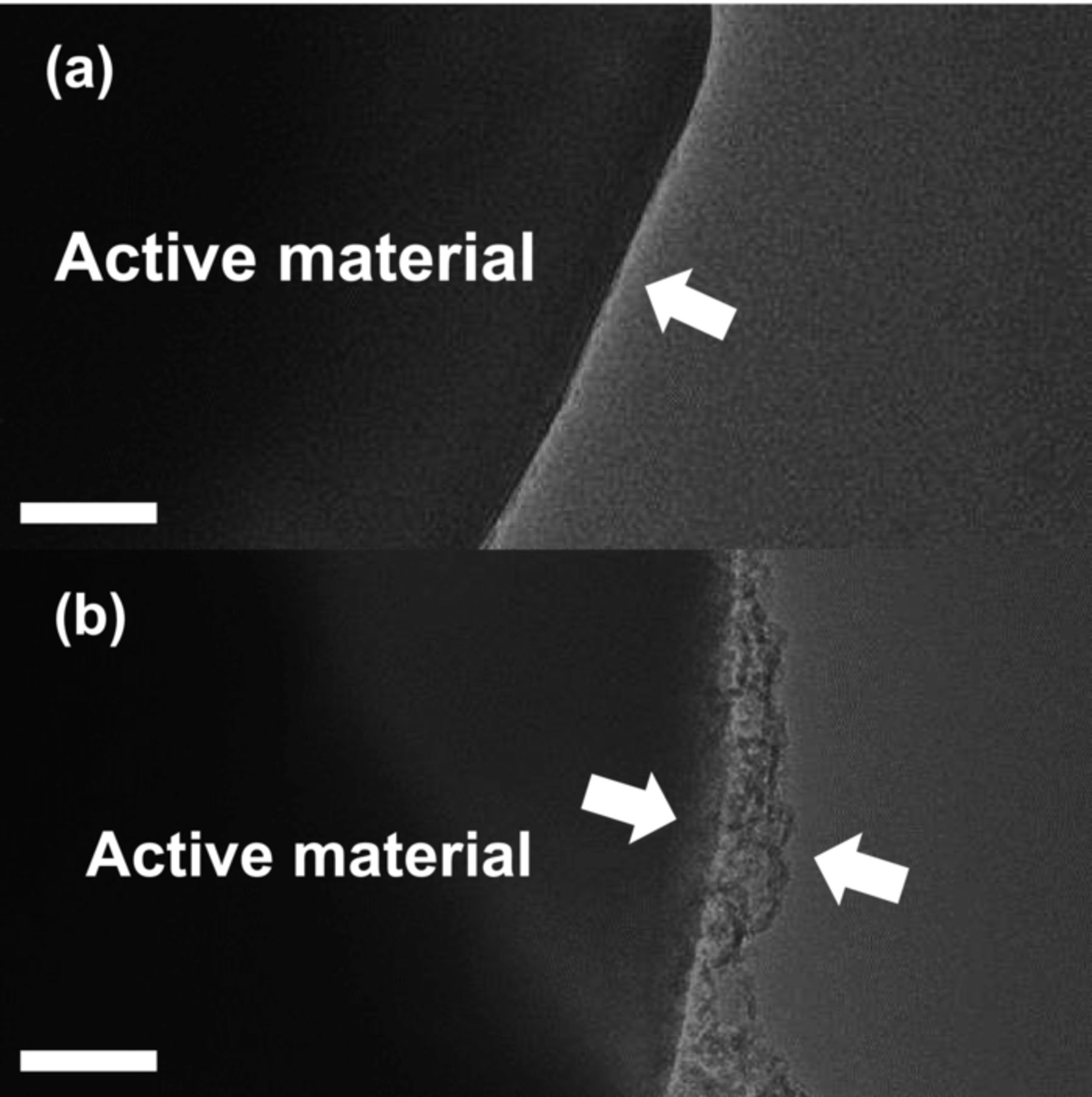
Figure 7. Bright-field TEM images of (a) bare and (b) Li2O-coated Li[Ni0.7Mn0.3]O2 after extensively cycling. The scale bar indicates 50 nm.
For the above reason, the extensively cycled bare and coated electrodes were analyzed by ToF-SIMS to unveil how the outermost original lithium compounds coating layers were altered. Four fragments are found in the mass range of 30.6–31.4: P+ (m = 30.97): CF+ (m = 30.99), Li2C+ (m = 31.01), and Li2OH+ (m = 31.03). P+ is derived from remained LiPF6 salt and CF+ is due to the presence of PVDF binder in the electrode. The development of Li2C+ intensity is evidently noticed after the cycling (Figs. 8a and 8b), compared to those fresh electrodes (Figs. 3a and 3b). In comparison with the intensity of the Li2OH+ fragment, the intensity of Li2C+ appears to be close to that of Li2OH+ for the bare electrode and the signal is somehow stronger than that of Li2OH+ for the Li2O-coated electrode. This result indicates that Li2CO3 layer resides just above the LiOH layer, as follows:
![Equation ([1])](https://content.cld.iop.org/journals/1945-7111/161/6/A920/revision1/jes_161_6_A920eqn1.jpg)
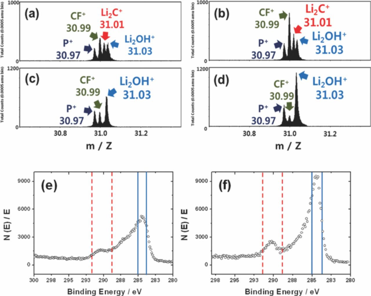
Figure 8. ToF-SIMS spectra for P+, CF+, Li2OH+ and Li2C+ of (a) bare, (b) Li2O-coated Li[Ni0.7Mn0.3]O2, (c) extensively cycled bare Li[Ni0.7Mn0.3]O2 electrodes, (d) extensively cycled Li2O-coated Li[Ni0.7Mn0.3]O2 electrodes. XPS carbon spectra after extensively cycled (e) bare Li[Ni0.7Mn0.3]O2 and (f) Li2O-coated Li[Ni0.7Mn0. 3]O2. The range from 284 eV to 285 eV indicates carbon. The range from 289 eV to 291.5 eV belongs to carbonate.
Aurbach's group20 suggested that CO and CO2 are anodic oxidation products of ethylene carbonate and dimethylene carbonate, which are used as solvents in the present study. Through the above reaction, these oxidation byproducts are deposited on the outer surface of residual LiOH layer forming the Li2CO3 layer but leaving water molecules (eq. 1). As is clear from the XPS results, more amount of Li2CO3 is formed on the outermost surface of the Li2O-coated electrode after the extensive cycling test (Figs. 8e and 8f). Hence, the relative intensity of Li2OH+ diminishes compared to the fresh state. Etching the electrode surface by Bi+ for 50s, the carbonate layer almost disappears, and only the LiOH layer is observed for both electrodes, meaning that the formed Li2CO3 layer is not thick.
Commonly, electrolyte using LiPF6 salt, which is unstable in the presence of H2O molecules and at high temperature or high operation voltage, is decomposed by the following equations:21,22
![Equation ([2])](https://content.cld.iop.org/journals/1945-7111/161/6/A920/revision1/jes_161_6_A920eqn2.jpg)
![Equation ([3])](https://content.cld.iop.org/journals/1945-7111/161/6/A920/revision1/jes_161_6_A920eqn3.jpg)
and
![Equation ([4])](https://content.cld.iop.org/journals/1945-7111/161/6/A920/revision1/jes_161_6_A920eqn4.jpg)
The produced LiF is generally deposited on the surface of active material. The LiF compound is not found on the XPS spectra for both fresh electrodes (Figs. 9a and 9c). After both electrodes were extensively cycled, the LiF is detected at 685 eV (Figs. 9b and 9d). In particular, the relative intensity of LiF binding energy is significantly higher for the coated material than that of bare one. It is believed that the formation of LiF is highly dependent on the amount of presenting water molecules in the electrolyte as expected from the above reactions. In this experiment, the difference is the presence of Li2O coating layer on the surface of active material. Through the anodic decomposition of electrolytic solvent, the produced CO and CO2 tend to bond with the hydrated Li2O layer, namely LiOH, forming Li2CO3 layer in the outermost surface, and this subsequently accompanies the formation of water molecules. In comparison with the bare material, the formed Li2CO3 layer seems thicker for the coated electrode, which also means generation of more amounts of water molecules in the electrolyte. This accelerates the decomposition of electrolytic salt, LiPF6, to lead to more formation of insulating LiF in the outermost surface. Therefore, the XPS result indicates the further development of LiF intensity for the Li2O-coated electrode after the cycling test. These layers, such as LiF, Li2CO3, and LiOH, coexist on the surface of the active materials, so that they impede the diffusion of lithium ions due to their insulating properties and thus deterioriate the electrochemical performances of active materials as described in Scheme 2. These series of sequential occurrence are affected by the presence of residual Li2O. Therefore, efforts should be made to minimize the amount of impurities on the surface of active materials to reduce these side reactions occurring in the interface of active materials and electrolyte during cycling. Surface modification capturing the residual Li2O compound would be a possible way to reduce the level of the residual lithium compounds on the surface of Ni-rich layer compounds.
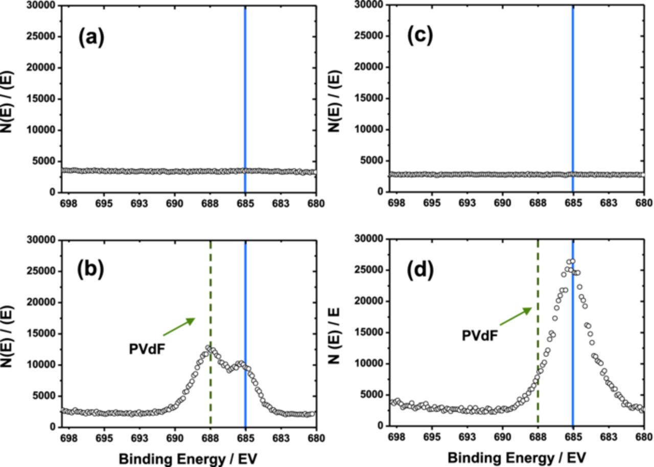
Figure 9. XPS spectra of fluorine; (a) before and (b) after extensively cycled bare Li[Ni0.7Mn0.3]O2; (c) before and (d) after extensively cycled Li2O-coated Li[Ni0.7Mn0. 3]O2. The peak at 685 eV indicates lithium fluoride (LiF).
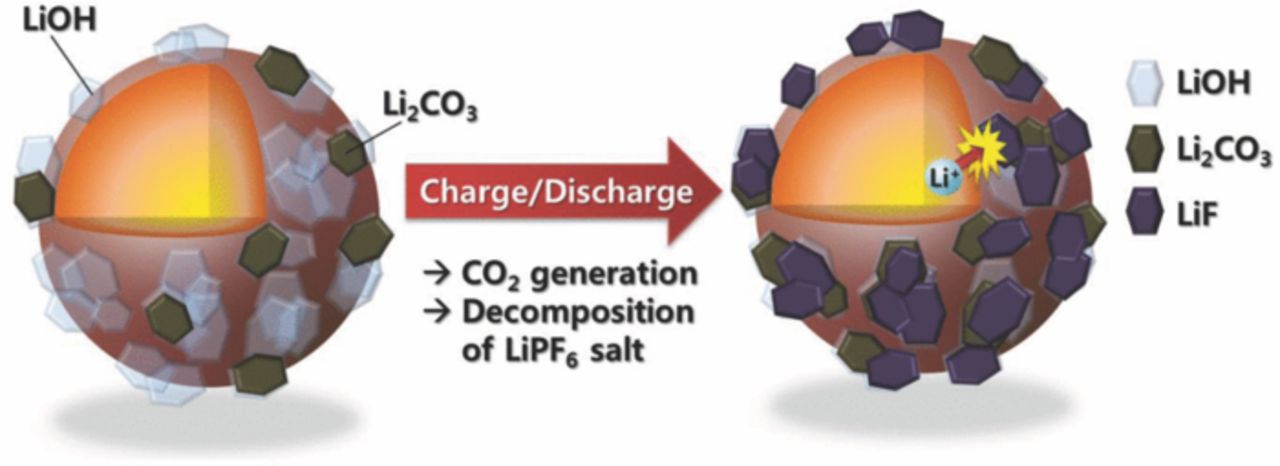
Scheme 2. Effect of the residual lithium on the surface of Li[Ni0.7Mn0.3]O2.
Conclusion
The effect of residual lithium on the surface of Li[Ni0.7Mn0.3]O2 is investigated in an artificial environment provided by Li2O coating. Exposure of the coated materials in air induces notable increase in the amount of LiOH as a major component and Li2CO3 as a minor component. Because of these contaminations, the surface-modified electrode shows unfavored electrode performances such as low capacity, large irreversible capacity, and poor capacity retention. It is found that the LiOH layer on the Li2O is transformed to Li2CO3 layers accompanied by the formation of water. This water molecule also accelerates the decomposition of LiPF6 salt, and this consequently gives rise to the formation of LiF toward the outermost surface of the active material. The progressive formation of insulating LiF layer impedes lithium diffusion and deteriorates the electrode performance during cycling. Therefore, we suggest that the concentration of surface lithium should be minimized to avoid these unfavorable effects.
Acknowledgments
The authors thank Miwa Watanabe, Iwate University, for her helpful assistance in the experimental work. This work was partially supported by the IT R&D program of MKE/KEIT [10041856] and the secondary battery R&D program for leading green industry of MKE/KEIT [10041094].