Abstract
Polymers have been widely employed as the binders, separators, separator modifiers and gel polymer electrolytes in lithium-sulfur batteries. Considering the special electrolyte system and discharge/charge mechanism, to verify whether the common polymer is applicable for Li-S battery is extremely necessary but often overlooked. In this paper the stability of some frequently-used polymersin the ether electrolyte(1 M LiTFSI + 0.2 MLiNO3/dioxolane (DOL) and 1,2-dimethoxyethane(DME) (1:1, v/v)) on the cycling and storage performances of Li-S batteryis examined by testing the solubility of the PEO, PVDF and PVDF-HFP particles/membranes in ether electrolyte and detecting the structure and composition changes of PVDF and PVDF-HFP membranes after cycling and storage as the separators of Li-S batteries. The results show that PEO particle and membrane both can dissolve in DOL and DME(1:1). PVDF and PVDF-HFP particles also dissolve in DOL and DME(1:1) but the membranes remain relatively stable, whereas PVDF-HFP react with Li2Sx in liquid Li-S cellto form sulfone, which induce the crystalline phase transformation (from α-phase to γ-phase) and cystallinity decrease. PVDF can also react with Li2Sxin liquid Li-S cell, but the action is less intensive than PVDF-HFP.
Export citation and abstract BibTeX RIS

This is an open access article distributed under the terms of the Creative Commons Attribution Non-Commercial No Derivatives 4.0 License (CC BY-NC-ND, http://creativecommons.org/licenses/by-nc-nd/4.0/), which permits non-commercial reuse, distribution, and reproduction in any medium, provided the original work is not changed in any way and is properly cited. For permission for commercial reuse, please email: oa@electrochem.org.
Lithium-ion (Li-ion) batteries have been widely applied in mobile electronics and power tools. The rapid propagation of portable electronic devices and electric vehicles has given rise to a corresponding increase in the demand for batteries with high specific energy. However, the energy density of current Li-ion battery is too low to meet this demand. So the research on advanced electrochemical energy storage technique has been stimulated. Rechargeable lithium-sulfur (Li-S) batteries have been the one of the most investigated high-performance batteries for the next generation due to their high theoretical energy density(2600Wh/kg), low cost and high abundance.1–7
Polymers have been widely employed as the binders, separators, separator modifiers and gel polymer electrolytes in lithium-ion batteries.8–11 The preparation process of Li-S batteries come of lithium-ion batteries, so the application of polymers are often duplicated directly. Polyvinylideneuoride (PVDF) and Poly(ethylene oxide) (PEO) are two most commonly used binders in both lithium-ion batteries and Li-S batteries.12 PEO, PVDF, poly(vinylidene fluoride-co-hexafluoropropylene) (PVDF-HFP) are all widely used for separators modification and gel polymer electrolytes in both lithium-ion batteries and Li-S batteries.13–16 Whereas, are they really suitable for Li-S batteries?
In Li-S battery, elemental sulfur and lithium metal are used as the cathode and anode active materials respectively. The sulfur forms various lithium polysulfides (Li2Sx (1<x<8)) as a result of the reduction during the discharge procedure. Liquid electrolytes with high solubility of lithium polysulfides are used in conventional Li–S batteries to improve the electronic conductivity of the sulfur cathode. Besides, the corrosion of lithium anode also raises special requirements for the electrolyte in Li–S battery. So the electrolyte for the Li-S battery is different from the Li-ion battery. The most used electrolyte in traditional Li-S battery is LiTFSI in combination of 1,3-dioxolane (DOL) and dimethoxyethane (DME) with LiNO3 as additive.17–19
Considering the special electrolyte system and discharge/charge mechanism, to verify whether the common polymer is applicable for Li-S battery is extremely necessary but often overlooked. In this paper, the stability of some frequently-used polymers in the liquid Li-S battery has been tested.
Experimental
Solubility test of polymer particles
PVDF (Kynar HSV 900), PVDF-HFP (Kynar Flex 2801) and PEO particles (MW = 5,000,000, Sigma-Aldrich) were respectivelyadded to the dioxolane (DOL) and 1,2-dimethoxyethane(DME) (1:1, v/v)) under stirring for 3 h.
Preparation of the membranes
Polymer membranes were prepared by tape casting method. PVDF and PVDF-HFP particles were added to N-methyl pyrrolidinone (NMP) respectively under stirring for 4 h. The resulting slurry was cast on a PTFE plate, and the solvents evaporated in an air-circulating oven at 50°C for 5 h. Then the membranes were peeled off and dried under vacuum at 50°C for 10 h. PEO particles were dispersed in acetonitrile to form a slurry. Then the slurry was prepared to membrane using the same method as PVDF and PVDF-HFP membranes do.
Solubility test of polymer membranes
DOL and DME(1:1, v/v) was added dropwise into PVDF, PVDF-HFP and PEO membranes respectively until the membranes were immersed.
Cell fabrication and performance measurement
Cells were fabricated using coin type cells (CR2016) by stacking cathode, anode and separator in a glove box filled with argon (99.9995%). Galvanostatically discharge/charge test was operated in the range of 1.5–2.8V at a current density of 500 mA/g. PVDF membrane, PVDF-HFP membrane and celgard 2325 were used as separators respectively. C/S composite and lithium metal were respectively used for cathode and anode of Li/S cell. 1 M LiTFSI + 0.2 MLiNO3/DOL and DME (1:1, v/v) was used as electrolyte.
Contrast cell fabrication
Aluminum foil and lithium metal were respectively used for cathode and anode of contrast cell (1), marked as Al-Li cell. C/S composite and stainless steel sheet were respectively used for cathode and anode of contrast cell (2), marked as S-Steel cell. PVDF-HFP membrane was stacked between celgard 2325 separator and C/S composite cathode of Li/S cell to prepare contrast cell (3), marked as PVDF-HFP(+). PVDF-HFP membrane was stacked between celgard 2325 separator and lithium anode of Li/S cell to prepare contrast cell (4), marked as PVDF-HFP(−).
Membrane treat in lithium polysulfide solution
The PVDF and PVDF-HFP membranes which had been immersed in lithium polysulfide solution for 10 days were marked as PVDF (Li2Sx) and PVDF-HFP(Li2Sx), respectively.
Characterization
Surface morphology of the polymer membranes were studied by a field-emission scanning electron microscope (SEM, Hitachi S-4800). X-ray diffraction (XRD) pattern was recorded with a Bruker D/8 X-ray diffractometer using Cu Karadiation (k = 1.5418 Å) to identify the crystal structure of polymer membranes. Fourier transform infrared (FT-IR) spectra were used to confirm the structure and composition of PVDF and PVDF-HFP membranes.
Results and Discussion
Solubility test of polymer particles and membranes
PEO, PVDF and PVDF-HFP particles are all dissolved in electrolyte after stirring, as shown in Figure 1. After immersed by ether electrolyte, PVDF and PVDF-HFP membranes remain stable but PEO membrane dissolved, as shown in Figure 2. The surface morphology changes of PVDF and PVDF-HFP membranes after immersed by electrolyte were shown in Figure 3. After immersed by electrolyte, the pores on the surface of PVDF membrane disappeared but the cracking and shedding turned up,similarly, the pores on the surface of PVDF-HFP membrane minified. It can be seen, although PVDF and PVDF-HFP membranes immersed electrolyte remains stable, they have swollen in electrolyte.
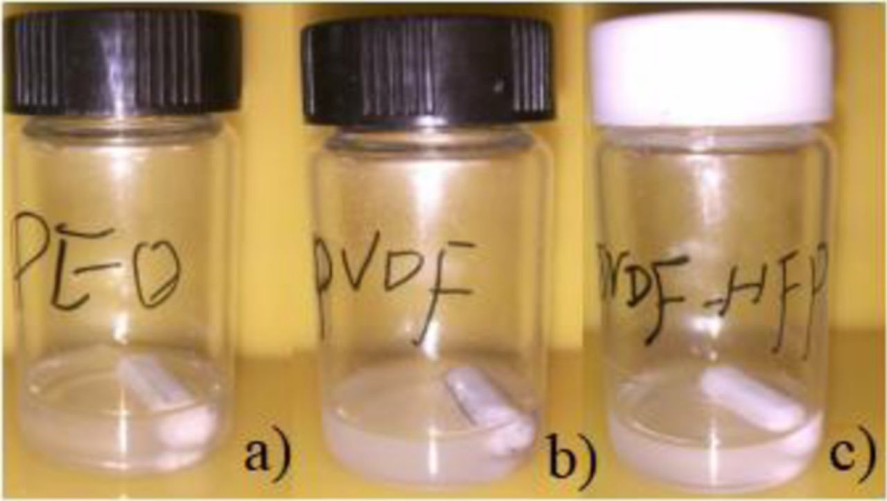
Figure 1. PEO (a), PVDF (b) and PVDF-HFP (c) particles dissolved in ether electrolyte after stirring.
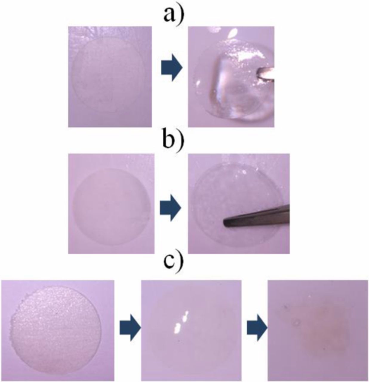
Figure 2. PVDF (a), PVDF-HFP (b) and PEO (c) membranes after immersed by ether electrolyte.
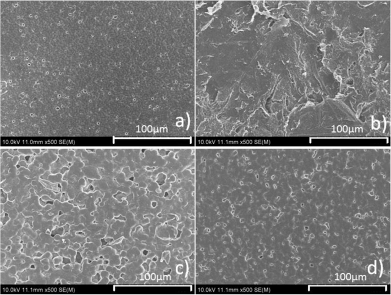
Figure 3. SEM images of PVDF (a, b) and PVDF-HFP (c, d) membranes before (a, c) and after (b, d) immersed by ether electrolyte.
Electrochemical performance of PVDF and PVDF-HFP membranes in Li-S cells
Figure 4a shows the initial discharge/charge curves of celgard 2325, PVDF and PVDF-HFP separators at the current of 500 mA/g between 1.5 and 2.8 V. All of the curves exhibit two discharging plateaus but at different voltage ranges. For celgard 2325 separator, the discharge plateaus at around 2.35 V and 2.1V could be attributed to lithiation of S8 molecules and the charge plateau at around 2.3V could be attributed to delithiation of S8 molecules. However, PVDF-HFP separator discharge plateaus fall to around 2.1V and 1.8V. Furthermore, PVDF separator discharge plateaus fall to around 1.8V and 1.5V. Severe polarization phenomenon of PVDF separator is attributed to high surface tightness (Figure 3d), membrane thickness(32μm) and crystallinity,20 which also led to high mechanical strength of membrane and long cycle life of cell, shown as Figure 4b. Besides, the polarization phenomenon of PVDF-HFP separator worse than celgard 2325 separator but lighter than PVDF separator attributed to high surface tightness (Figure 3b) but lower membrane thickness(21μm) and lighter crystallinity,21 which also led to lighter polarization maybe with constantly dissolution of membrane as the cycles go on and internal short circuit of cell after 48 cycles, shown as Figure 4b.
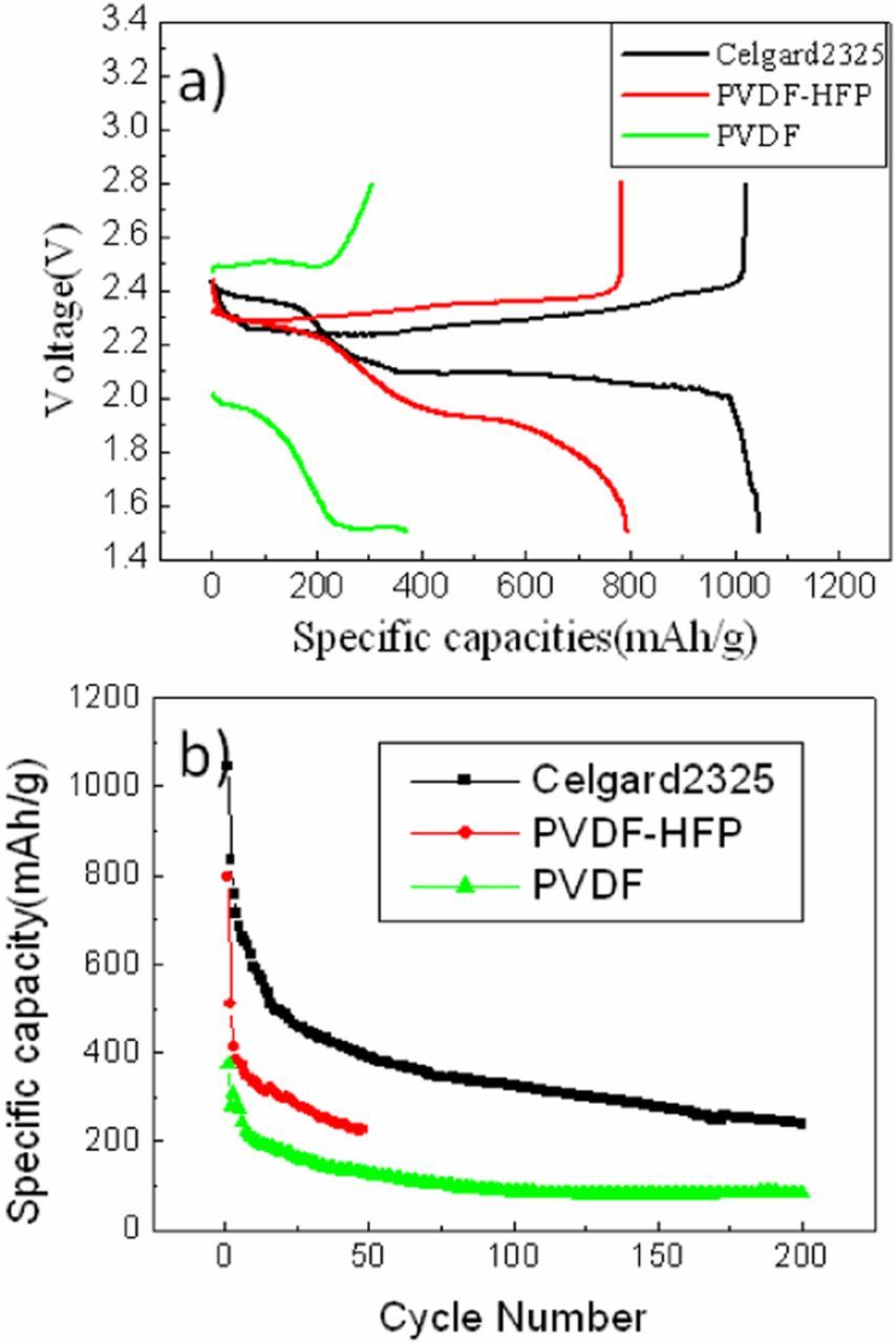
Figure 4. Initial discharge/charge curves (a) and cycling specific capacity profiles of celgard 2325, PVDF-HFP and PVDF membranes (b) at a current density of 500 mA/g.
Changes of PVDF and PVDF-HFP membranes after cycles
The colorless and transparent PVDF and PVDF-HFP membranes turned black more or less after cycles, shown as Figure 5a and Figure 5b, which revealed some physical or chemical reactions of PVDF and PVDF-HFP membranes in Li/S cell or during cycles. After cycles, celgard 2325 turned a little yellow but still was transparent, shown as Figure 5c. In consideration that PVDF-HFP membrane turn black thoroughly, take PVDF-HFP membrane as the representative to study the cause of blackening.
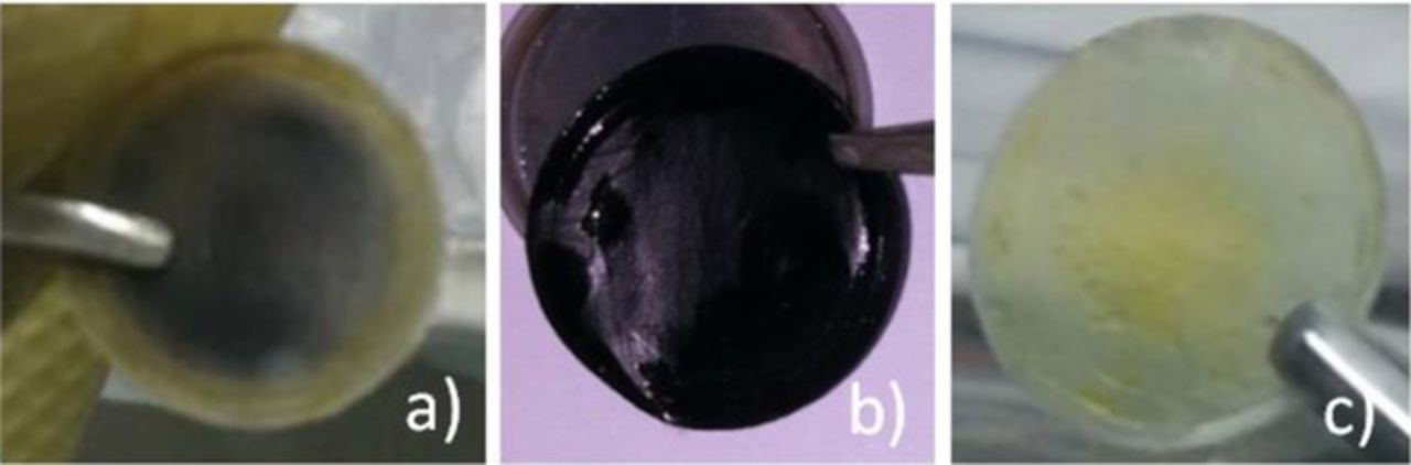
Figure 5. PVDF (a), PVDF-HFP (b) and celgard 2325 (c) after cycles.
The causation of blackening
The most intuitive reason of blackening may be the carbon on the cathode is immersed with the electrolyte into the membrane. To analyze the components of black material on PVDF-HFP membrane after cycles, SEM, EDS mapping analysis and XRD were used. Figures 6–7 are SEM images and elemental maps of PVDF-HFP and PVDF-HFP cross section after cycles. Figure 8 is the XRD spectra for PVDF-HFP membrane. Figure 6 shows the surface of PVDF-HFP membrane was covered by nanoparticles and the elements C, F, S were visuallyobserved on the maps of PVDF-HFP membrane. It is obvious that the fluorine (Figure 7c) and sulfur (Figure 7d) are homogenously dispersed on the surface, but the carbon is not dispersed uniformly and failed to match with nanoparticles. Meanwhile, the maps of the cross section show the homogenous distribution of fluorine and sulfur at the longitudinal direction, but carbon is more dispersed on the surface of membrane. In view that PVDF-HFP membrane turn black uniformly all through, the black materials should be homogenous dispersed in the membrane. So it may be sulfur instead of carbon that makes the membrane black. Meanwhile, the simple carbon and sulfur peaks cannot be observed in the XRD spectrum (Figure 8), which means the sulfur and carbon in PVDF-HFP membrane is not single substances. So, the carbon element on the surface of membrane should come from the electrolyte instead of conductive agent and the sulfur element should come from polysulfide instead of sulfur. Causation of blackening may be the cathode, anode, electrolyte or all of them. To further confirm the reason, some contrast cells were prepared and shelved for 10 days. Figure 9 shows the membranes in different contrast cells after shelving for 10 days. PVDF-HFP membrane in Li-S cell after shelving for 10 days turn black (Figure 9a), that means cycle is not the neccesary factor of blackening. PVDF-HFP membranes in Al-Li and S+Steel cells have not turn black (Figure 9b and Figure 9c), that means the causation of blackening could not be the cathode, anode and electrolyte but all of them. PVDF-HFP(+) turns black totally (Figure 9d) and PVDF-HFP(−) turns black lightly (Figure 9e), that means the causation should be something generating from cathode and capable of diffusing to anode side. So it is inferred that the causation should be the intermediate product Li2Sx, which is confirmed by Figure 9f, as shows that PVDF-HFP immersed by Li2Sx solution turn black.
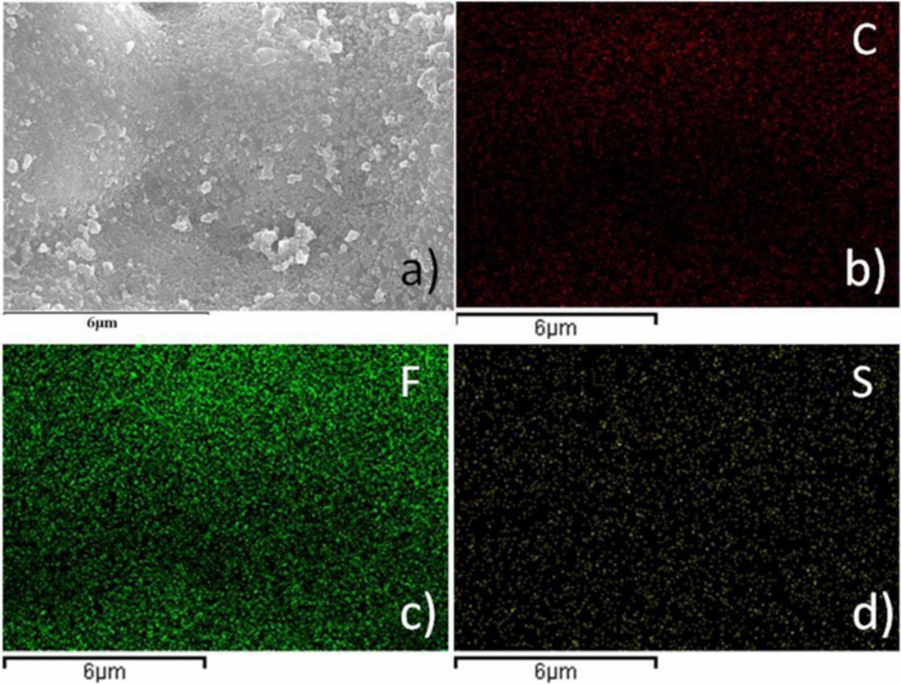
Figure 6. SEM image (a) and elemental maps of PVDF-HFP membrane after cycles corresponding to (b) C, (c) F, (d) S.
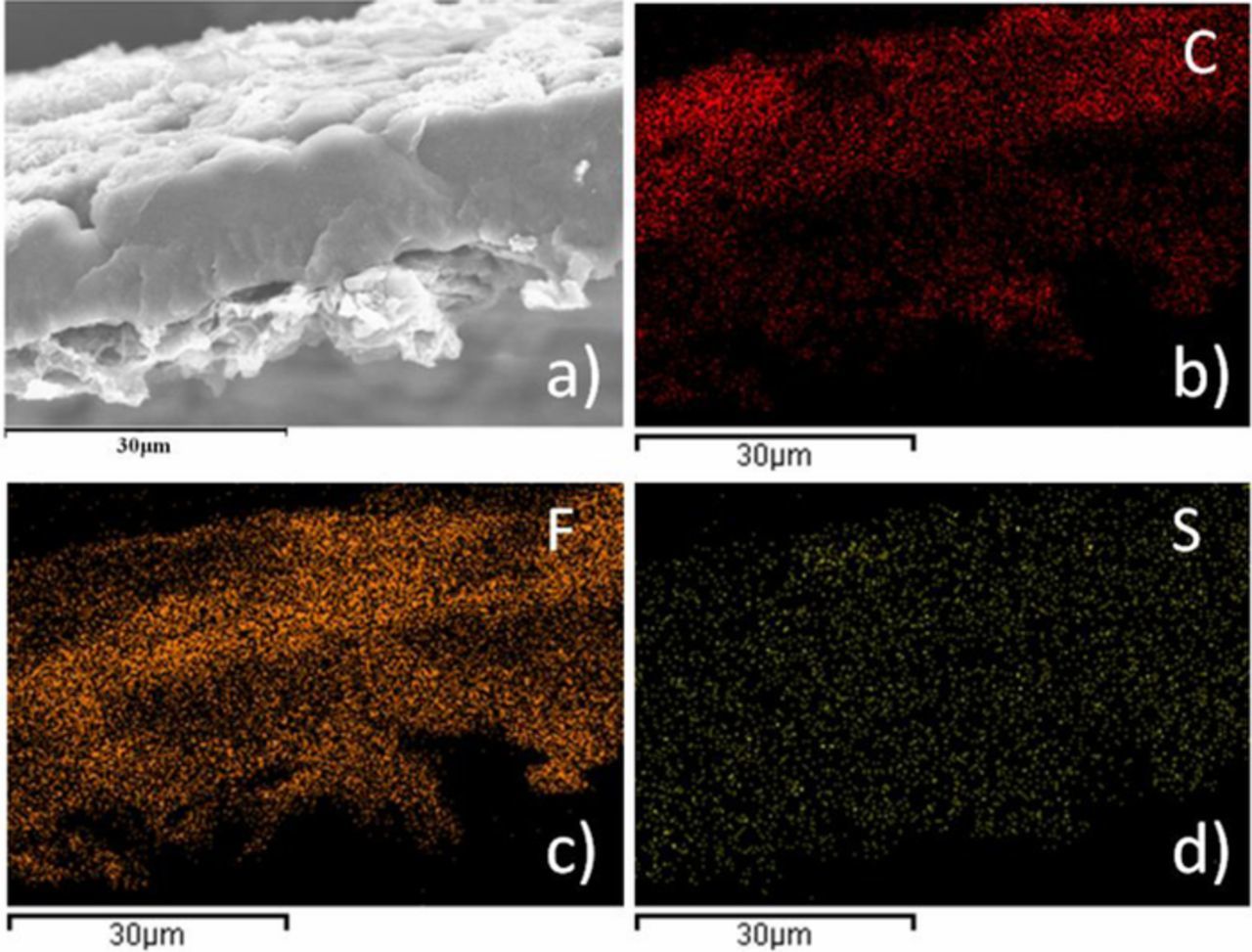
Figure 7. SEM image (a) and elemental maps of PVDF-HFP membrane cross section after cycles corresponding to (b) C, (c) F, (d) S.
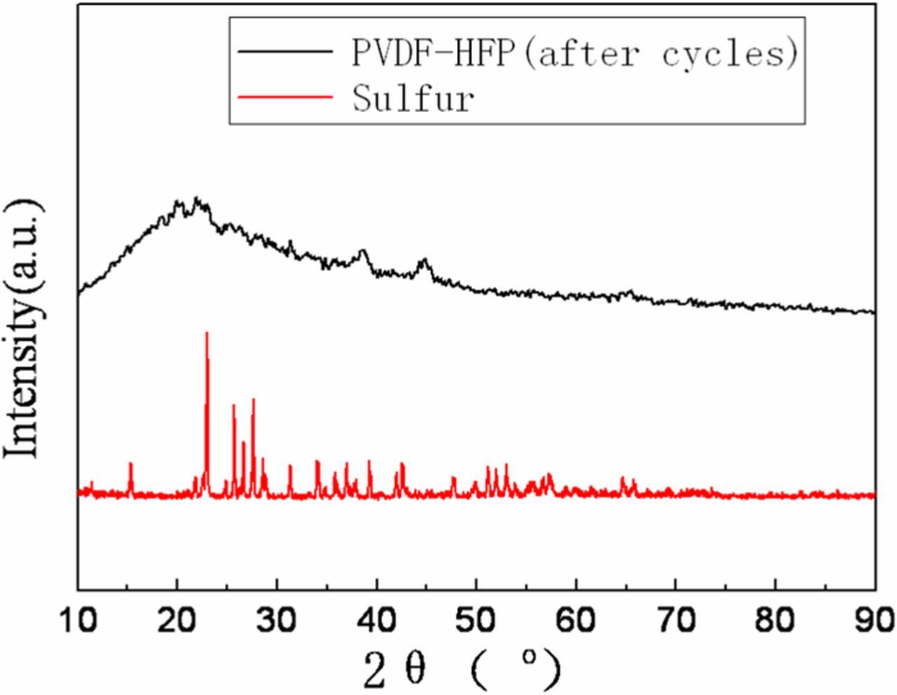
Figure 8. XRD spectra for PVDF-HFP membrane, celgard 2325 and elemental sulfur.
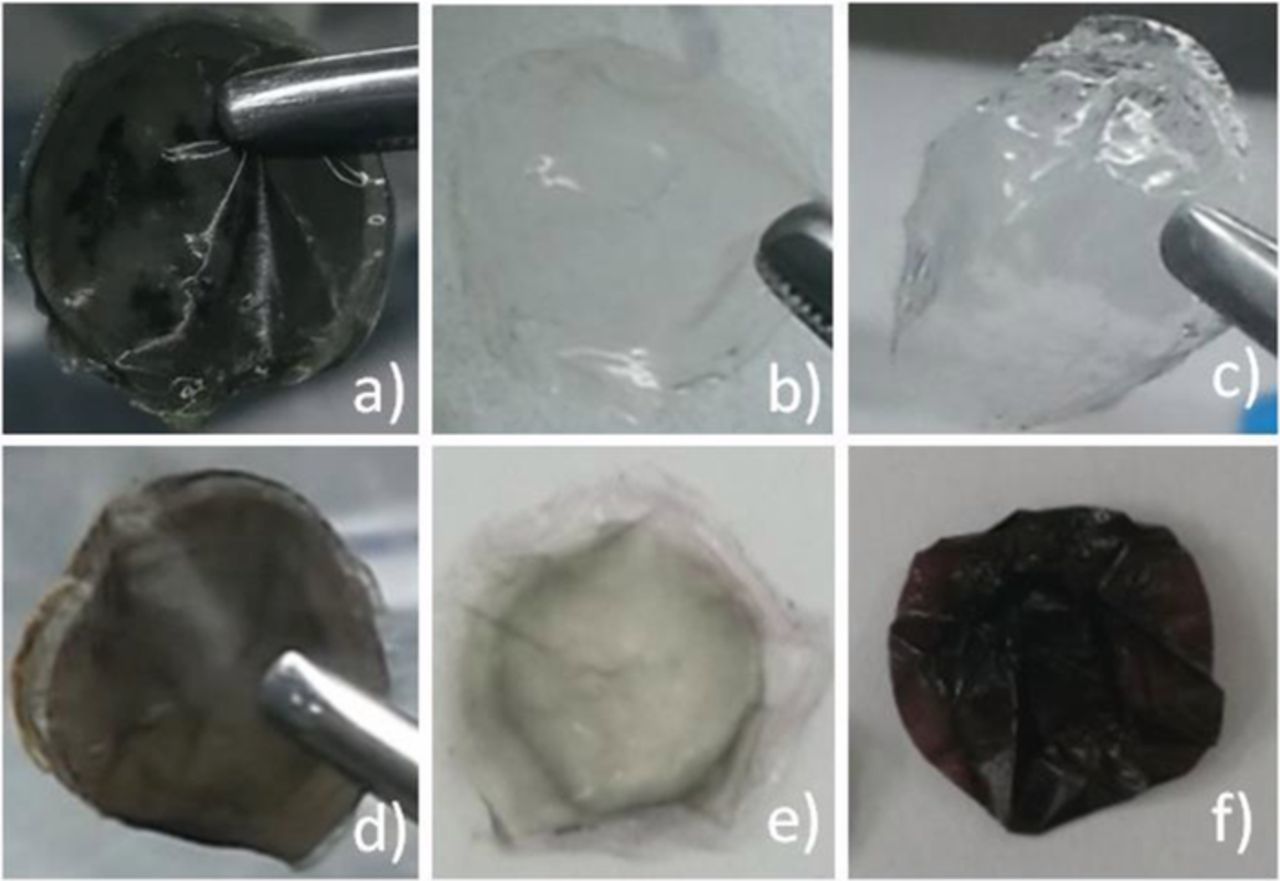
Figure 9. PVDF-HFP membranes in different cells after shelving for 10 days (a. in Li-S cell; b. in Al-Li cell; c. in S-Steel cell; d. PVDF-HFP(+); e. PVDF-HFP(−); f. PVDF-HFP(Li2Sx)).
Transformations of PVDF and PVDF-HFP membranes after action
XRD and FI-IR were used for PVDF-HFP membranes treated in different conditions to study the structural transformation of PVDF-HFP membranes. Figure 10a shows the XRD patterns for pure PVDF-HFP membrane, PVDF-HFP(+), PVDF-HFP(−) and PVDF-HFP(Li2Sx). Pure PVDF-HFP membrane is crystalline and shows itspeaks at 2-Theta = 18.2, 20, 26.6 and 38, correspond to the (1 0 0), (0 2 0), (1 1 0) and (0 2 1) crystalline peaks of PVDF. Peaks found at 18.2, 26.6 and 38 were completely destroyed and the peak found at 20 disappeared gradually in PVDF-HFP(−), PVDF-HFP(+) and PVDF-HFP(Li2Sx), that meanscystallinity of the PVDF-HFP membrane was disrupted by the addition of Li2Sx. The XRD patterns for PVDF-HFP(Li2Sx) and PVDF-HFP after cycles (Figure 8) show the humps, which is a typical characteristic of amorphous materials. The segmental mobility of polymer chains is much higher in amorphousregions than thecrystalline. The amorphous nature producesgreater ionic diffusivity in accordance with the high ionic conductivity but low mechanical strength, which is quite in accord with the electrochemical performance (Figure 4).
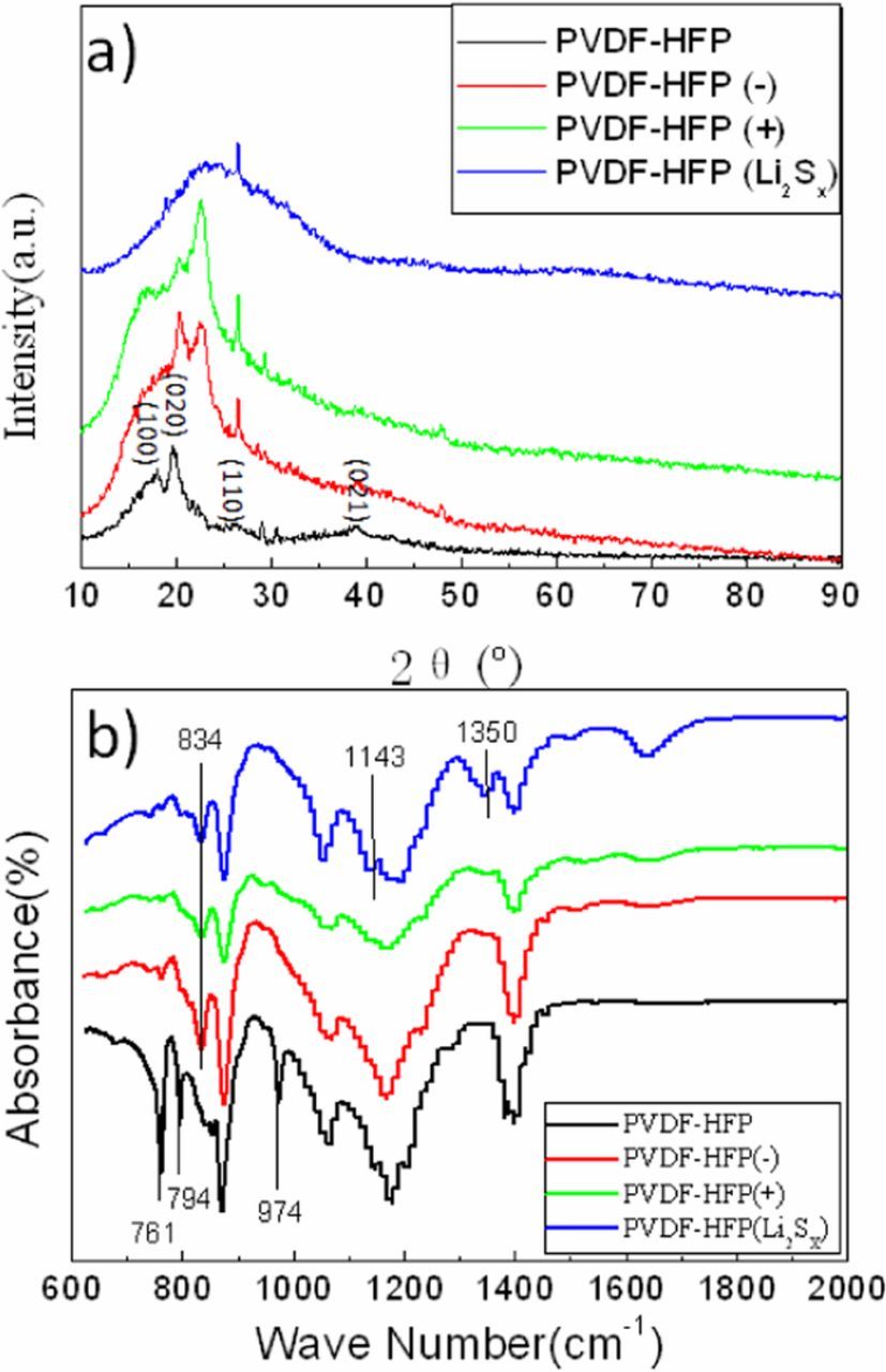
Figure 10. XRD (a) and FT-IR (b) spectra of the PVDF-HFP membranes in different cells after shelving for 10 days.
Figure 10b shows FT-IR spectra for pure PVDF-HFP membrane, PVDF-HFP (+), PVDF-HFP(−) and PVDF-HFP(Li2Sx). The peaks near 488, 532, 615, 764, 795, 974 and 1149 cm−1 are for the non polar α-phase of PVDF and its co-polymer PVDF-HFP, while those near 431, 776, 812, 833 and 1233 cm−1are exclusive for the γ-phase. The peaks near 761,794 and 974 cm−1 are observed in pure PVDF-HFP membrane FT-IR spectrum but all of them disappear and the peak near 834 cm−1 turns up in PVDF-HFP(+), PVDF-HFP(−) and PVDF-HFP(Li2Sx) FT-IR spectrum, which means the non polar α- phase PVDF-HFP membrane transform to γ-phase after reacting with Li2Sx. The peaks at 1143 and 1350 cm−1 are observed in PVDF-HFP (Li2Sx), which are ascribed to the sulfone formation. The oxygen element in sulfone is presumably derived from the electrolyte.
Figure 11 shows XRD and FT-IR spectra for pure PVDF membrane before and after being immersed by Li2Sx solution. The appearance of hump shows the amorphous structure of PVDF (Li2Sx). The peaks near 761,794 and 974 cm−1 diminish and the peak near 1231cm−1 turn up, which means the non polar α-phase PVDF membrane transform to γ-phase after reacting with Li2Sx. The transformations of crystalline phase and cystallinity are according with the PVDF-HFP membrane, but the peaks at 1143 and 1350 cm−1 have not been observed, which means the action of PVDF in Li-S cell is not as intensive as PVDF-HFP. The same result is illustrated by photo of PVDF membrane after cycles (Figure 5a).
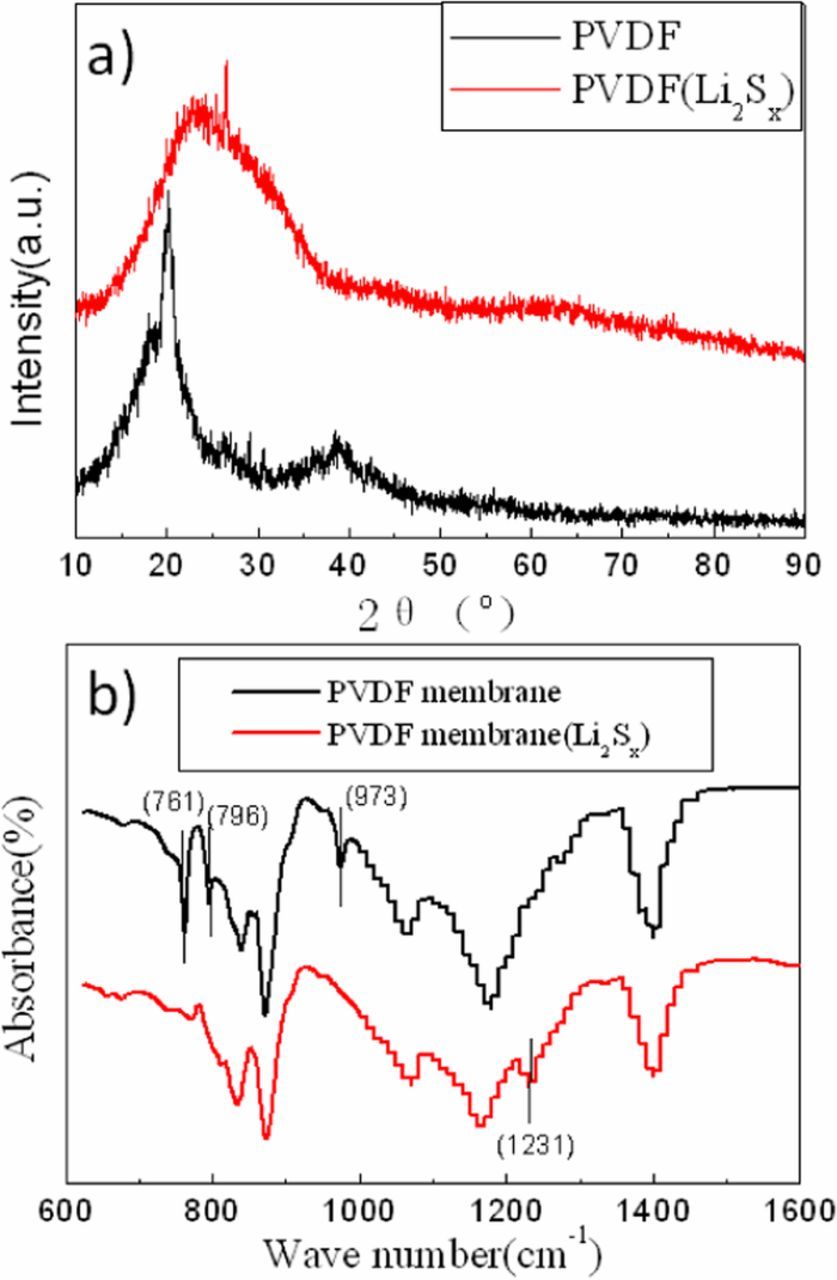
Figure 11. XRD (a) and FT-IR (b) spectra of the PVDF membranes in different cells after shelving for 10 days.
In summary, PVDF-HFP can react with Li2Sx in liquid Li-S cell to form sulfone, which induce the crystalline phase transformation and cystallinity decrease of PVDF-HFP membrane. PVDF can also react with Li2Sx in liquid Li-S cell, but the action is less intensive than PVDF-HFP.
Conclusions
This work reveals that some polymers widely used nowadays are not totally stable in liquid Li-S cell. PEO particle and membrane dissolve in DOL and DME(1:1). PVDF and PVDF-HFP particles also dissolve in DOL and DME(1:1) but the membranes remain relatively stable, whereas PVDF-HFP react with Li2Sx in liquid Li-S cellto form sulfone, which induce the crystalline phase transformation (from α-phase to γ-phase) and cystallinity decrease. PVDF can also react with Li2Sxin liquid Li-S cell, but the action is less intensive than PVDF-HFP. However, this does not mean that the polymers are useless in liquid Li-S cell. More appropriate applications need to be explored based on these performances.
ORCID
Jingying Xie 0000-0002-3877-8745