
Abstract
The application of redox catalysis to the electrochemical dehydrogenation of organic molecules is of interest for a hybrid flow battery/fuel cell system for energy storage. The process of redox catalysis has been known and well studied theoretically and experimentally for several decades. Studies of redox catalysis can be instrumental in determining mechanistic aspects of electrochemical reactions and in measuring basic thermodynamic and kinetic parameters. Redox catalysis has the ability to reduce the overpotential of the dehydrogenation reaction used in such a system as well as to alter the course of the reaction to achieve higher efficiencies. The mechanism of catalysis can involve an ECE-type reaction or a CEE-type reaction. In either case the acid-base chemistry of the medium is critical. Preliminary results of catalytic current measurements as a function of redox catalyst, base concentration, and base strength are described along with possible reaction mechanisms.
Energy storage and conversion systems that use rechargeable liquid fuels may solve some of the issues that face conventional batteries and fuel cells. Lithium ion batteries suffer from irreversible capacity loss, the inability to be rapidly recharged, leading to “range anxiety” in transportation applications, and many of the battery components (current collectors, separator, electrolyte) do not store any energy.1 Fuel cells produce energy as long as they are continuously supplied fuel and oxidant, but production, distribution and storage of the most commonly used fuel (H2 gas) is challenging.2 Furthermore, hydrogen fueled polymer electrolyte membrane (PEM) fuel cells are only moderately efficient in converting the fuel energy to electricity, which further limits range for transportation. Alternatively fueled systems such as Direct Methanol Fuel Cells (DMFC) are even less efficient due to poor reaction kinetics but the storage issue is alleviated through the use of a liquid fuel, which can be distributed using presently existing infrastructure. A further drawback of DMFC lies in the release to the atmosphere of product CO2 in an uncontrolled fashion, a drawback that is common to fuel systems that involve direct reaction of the fuel with oxygen.
An alternative fuel system was suggested by Pez and coworkers3,4 and has been the focus of increasing attention.5–8 Organic liquids such as N-ethylcarbazole are hydrogenated (see Figure 1) to provide the charged fuel for distribution and storage. The hydrogen is released on site by use of a thermal reactor9 and fed to a conventional fuel cell where it is converted to electricity, water and heat, which is recycled to the thermal reactor. The dehydrogenated fuel would then be recovered for rehydrogenation to complete the charge/discharge cycle. A simpler and potentially more efficient system would involve direct electrochemical dehydrogenation of the liquid fuel in the fuel cell.10,11 This system relies on a fuel that acts as a “virtual hydrogen storage” material, by releasing protons and electrons directly in the presence of an appropriate electrocatalyst.9 This allows for the cell voltage to be optimized by tuning the potential of the electrochemical dehydrogenation reaction, which can open up the possibility of obtaining an anodic voltage that is negative of hydrogen,10 thereby leading to increased cell voltages. Additionally, successful implementation of the system is not tied to making one particular fuel/catalyst combination work. The system can be recharged by either applying electric current to reverse the reaction and regenerate the charged fuel, or by removing and replacing the depleted fuel. The latter recharging method may prove particularly useful if the system is used to power vehicles, as the current infrastructure of worldwide liquid fueling stations could be modified and retained and the need for storing free hydrogen eliminated.
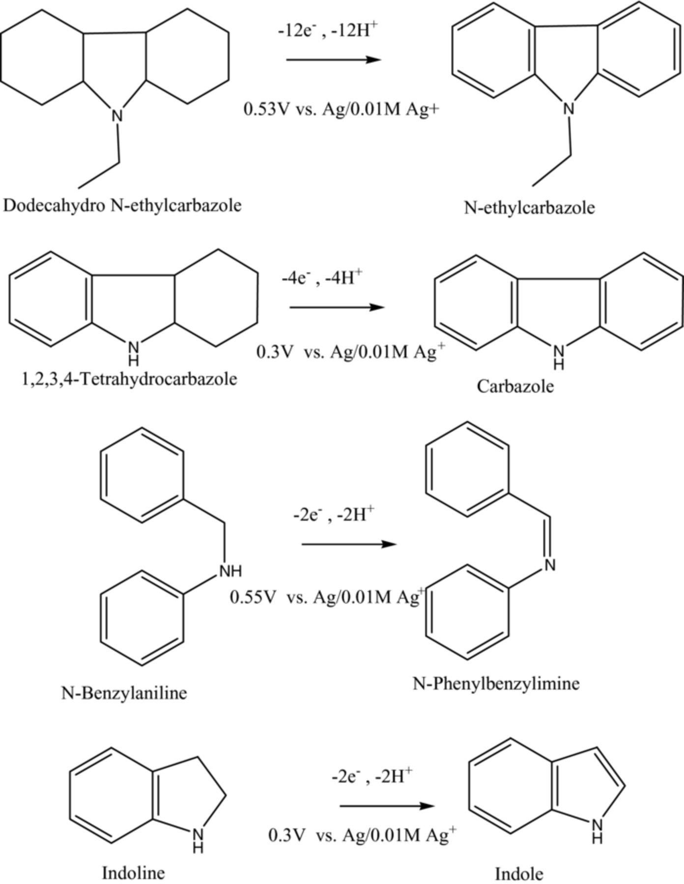
Figure 1. Potential fuel molecules and model substrates examined to facilitate understanding.
Although there are many technical challenges that face energy storage devices, a most significant challenge is cost. One way to increase the cost-effectiveness of such devices is to focus on complete understanding the chemistry of the system so that sources of inefficiency on a molecular level can be identified and addressed. Requirements for such an energy storage system include: selection of the correct hydrogen carrier liquids that have sufficient current density at accessible potentials; identification of electrocatalysts for hydrogenation/dehydrogenation as well as oxygen reduction and evolution reactions that have high rates at the desired voltages; membranes that are selective for rapid proton transport while restricting the crossover transport of fuels and oxidant; membrane-electrode assemblies that provide rapid transport of all the reactants and products; and the overall durability of all of the components. These are requirements that are common to all practical electrochemical systems, whether for the purpose of synthesis or energy storage and conversion. The work reported here is focused on examining model catalysts and substrates closely related to practical fuels with the goal of understanding the kinetic and mechanistic aspects of electrochemical dehydrogenation reactions in order to identify promising catalyst/fuel combinations for the system.
Figure 1 shows a plausible fuel, dodecahydro-N-ethylcarbazole, which has been investigated for use in thermal hydrogen release schemes3,5,6 as well as in electrochemical dehydrogenation.10 The dehydrogenation process involves 12 electrons and 12 protons as well as numerous intermediate compounds, amongst which could be the N-ethylatedtetrahydrocarbazole. Commercially available tetrahydrocarbazole is shown as a possible intermediate which could undergo a 4 electron oxidation to carbazole. The dehydrogenation of these multi-hydrogenated compounds by oxidation directly at a carbon electrode occurs at 0.3–0.55 volts versus Ag/0.01M Ag+ in acetonitrile and can involve a large variety of intermediates that can lead to side products in addition to the desired dehydrogenation products. The oxidation potentials observed are very dependent upon the presence of acids and bases as are the exact product distributions obtained which will be reported in full in a later publication. In order to simplify the chemistry for the initial studies, benzylaniline12 and indoline13 have been studied. These substrates undergo the loss of two protons and two electrons (Figure 1) and can be catalyzed by redox mediators to occur at lower overpotentials than directly at the electrode, which is obviously of great interest for energy conversion devices but which can also be useful for tuning catalyst potentials for selectivity in synthetic applications. For example, direct indoline electro-oxidation yields a dimer product14 while redox catalysis can be used to avoid this and push the reaction in the desired direction (formation of indole). The use of redox catalysis combined with study of the direct electrochemical oxidation at the electrode can be helpful in mechanistic diagnosis and determination of kinetics.15 Rate constants for the catalysis can be estimated using equations that have been developed through classical electrochemical techniques and were previously reported by Saveant.15–20
Ferrocene and its derivatives are common mediators for oxidation reactions and turn out to be suitable catalysts for oxidative dehydrogenation reactions.21–24 The catalysis of the above substrates is weak in acetonitrile alone and requires the presence of a large excess of base (e.g. imidazole) to drive the catalysis. The relationship between mediator potential, substrate and the nature of the base has been explored and some preliminary preparative electrolysis results are reported. In addition to ferrocene derivatives, 2,3-dichloro-5,6-dicyanobenzoquinone (DDQ), shown previously to catalyze dehydrogenation,12 was examined electroanalytically and rate constants have been estimated. The two mediators were chosen for study due to their reversible redox potentials, which are different enough from each other to alter the strength of potential-dependent outer-sphere redox catalysis (Ferrocene: 0.087 V vs. Ag/0.01M Ag+, DDQ: 0.23 V vs. Ag/0.01M Ag+). We were additionally interested in the fact that DDQ can catalyze the reaction either by outer-shere electron transfer or by hydride transfer whereas ferrocene can only act by electron transfer. It is an objective of this study to investigate different possible mechanisms and different reaction schemes for energy conversion purposes are discussed as well as steps that can be taken to steer these reactions in the desirable direction.
Experimental
Materials
All chemicals and solvents were reagent grade or better, obtained from Sigma-Aldrich (Milwaukee, WI), or Alfa Aesar (Ward Hill, MA), and used as received unless otherwise noted. Acetonitrile (HPLC grade) for all electrochemical experiments was obtained from Burdick and Jackson (Morristown, NJ) and used without further purification.
Electrochemical measurements
Electrochemical experiments were performed on a Gamry (Warminster, PA) Reference 600 potentiostat/galvanostat/ZRA that was under computer control using Gamry's Framework (v. 5.61) software. All cyclic voltammograms were measured using a three-electrode cell with an alumina polished glassy carbon working electrode (area = 0.0707 cm2), an Ag/Ag+ non-aqueous reference electrode (0.01 M AgNO3 in supporting electrolyte solution), and a platinum counter electrode. The supporting electrolyte was 0.1 M tetraethylammonium tetrafluoroborate in acetonitrile in both anode and cathode compartments and each solution was purged with argon for about 10 minutes prior to starting measurements. The catalyst, fuel, and base concentrations, as well as the scan rates, were varied with each experiment.
Controlled potential electrolysis was performed using a two compartment cell with a medium porosity glass frit separator. The working electrode was a carbon felt (Alfa Aesar) (3 × 3 × 0.5 cm) connected by a platinum wire. The counter electrode was a platinum gauze and the reference was as described above. The solution in the working compartment was agitated by means of a magnetic stirrer. Potential control was obtained by use of a PAR 173 potentiostat with a PAR 276 computer interface and the experiments were controlled using CorrWare software. The solutions were carried out under an argon atmosphere for 20 hours. The resulting solutions were then analyzed using HPLC (Agilent 1120) with a Zorbax C18 column and o-terphenyl as a standard for quantitation.
Kinetic calculations
Rate constants were estimated using a method developed by Saveant et al.16,18,19 This method involves evaluating the catalytic current at different fuel/catalyst ratios and scan rates. In these experiments, ratios of fuel to catalyst (γ) were 1, 4, 20, and 100 while the catalyst concentration was held constant (1 mM). The initial current of the catalyst alone (io) is first determined at each scan rate and then the peak current of the catalyst is multiplied by the ratio of the fuel to catalyst to give a value for ioγ. The catalytic current (icat) is determined as the peak current measured with both the fuel and catalyst present at each scan rate.
Next, the catalytic current (icat), is divided by the values obtained for ioγ for each respective fuel concentration and scan rate to get a value for icat/ioγ at each fuel/catalyst ratio. These values can then be used with the dimensionless working curves calculated and reported by Saveant and coworkers to obtain a value for λ1, which can then be used to calculate the rate constant.16
Working curves for each ratio (γ) used were reproduced from Saveant's published data and are shown in Figure 2. The numbers shown on the plot are the fuel/catalyst ratio (γ) and only the area of interest, based on the calculated icat / ioγ values, is shown. A value of λ1 was estimated from each CV experiment using the respective working curve.
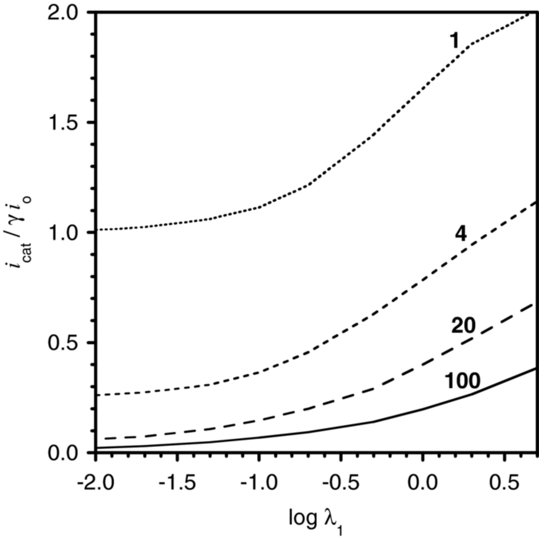
Figure 2. Dimensionless working curves for estimating rate constants (the numbers are γ, fuel/catalyst ratio).16
Using the values of λ1 obtained from the curves in Figure 3, the rate constant (k) can be calculated from the following equation:
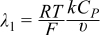
where R is the gas constant (8.314 J/mol·K), T is the absolute temperature (298 K), F is Faraday's constant (96485.339 C/mol), Cp is the concentration of catalyst (0.001 M for all experiments here), and υ is the scan rate (0.050, 0.100, 0.150, 0.200, 0.300, 0.400 or 0.500 V/s).
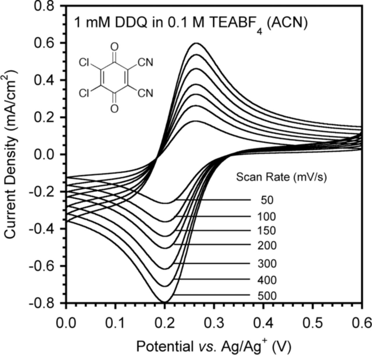
Figure 3. CVs showing the scan rate dependence of the redox current of DDQ.
Results and Discussion
Kinetics
A primary goal of these experiments is to determine the operating mechanism under the varying conditions and to measure the rate constants for the redox catalysis observed. If the rate constants measured are consistent with Marcus Theory for either outer sphere or inner sphere electron transfer, a catalytic mechanism can be proposed. A solid understanding of the reaction mechanisms is important as new catalyst/fuel combinations are proposed; sources of inefficiency at a fundamental level can be identified and addressed.
For the initial experiments described, outer sphere electron transfer (simplest case) is assumed with three reactions occurring. A summary of the reactions and possible scenarios (cases) follows. P/Q is the redox couple (catalyst), A is the fuel (substrate), and B is a reactive intermediate.19



Case 1 involves reaction 3 being much faster than reaction 2 all of B will go to the product by reaction 3 and the reaction rate (and therefore catalytic current) will be determined by the forward rate constant of reaction 2 (case 1 is assumed for the systems studied here).
Case 2 involves reaction 3 being much slower than reverse reaction 2; therefore reaction 2 is in equilibrium and the catalytic current is determined by the forward rate constant over the reverse rate constant of reaction 2 times the rate of reaction 3.
Case 3 is complicated; both reactions 2 and 3 have the same rate.
Based on the results of the rate constant calculations certain criteria can be evaluated as to whether they are consistent with the mechanistic assumption. For example, one of the confirmations that the kinetics of the system follows case 1 is that the estimated value of the rate constant is independent of the fuel/catalyst ratio (γ), the scan rate (υ), and the catalyst concentration (Cp). Another confirmation that the kinetics are consistent with case 1 is that the value for icat/ioγ increases with increasing catalyst or fuel concentration. If these conditions are not met, the kinetics may follow case 2, or be even more complicated. These experiments are performed by evaluating the catalytic current at different fuel and catalyst concentrations and at different scan rates, by cyclic voltammetry.
Mechanism
A proposed general mechanism for the redox catalysis investigated here is shown in Scheme 1. The catalyst (ferrocene in the example below) is oxidized in the first step and then an electron is transferred from the substrate to form a radical cation and regenerate the catalyst. The next step, deprotonation, drives the catalysis and forms a radical that can then lose an electron, generating a cation. Loss of a second proton forms the desired dehydrogenated product or the cation can hydrolyze to form an undesired product. Assuming that the deprotonation step is fast, the measured catalytic current will correspond to the rate of electron transfer between the substrate and the catalyst and the system can be optimized to maximize this rate. In these experiments a large excess of base was used to facilitate deprotonation (in an actual energy storage system the protons will pass through the membrane). Once catalytic activity is confirmed, bulk electrolysis can be used to identify and quantify the products.
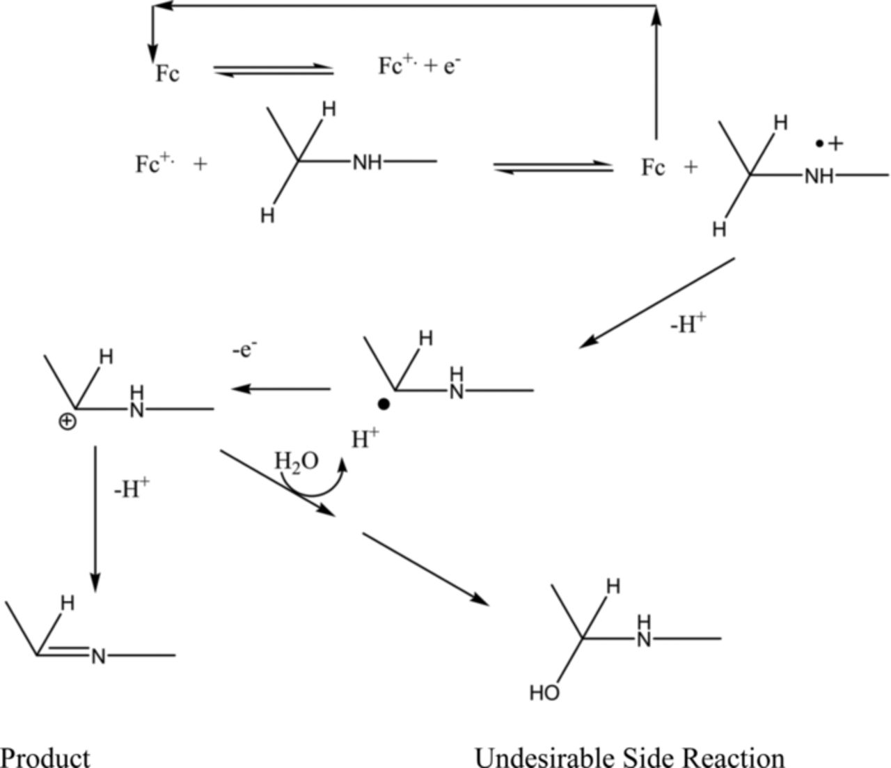
Scheme 1. General mechanism for redox catalyzed dehydrogenation.
DDQ
Although the majority of the work described focuses on ferrocene catalysts, DDQ has been shown to catalyze benzylaniline oxidation12 and was examined as a starting point for evaluating other catalysts. DDQ undergoes a reversible 1 electron reduction to a radical anion as shown in the cyclic voltammograms in Figure 3 (the peak separation is approximately 60 mV and the maximum current varies linearly with the square root of the scan rate). A second reversible reduction to the diradical is also observed at more negative potentials (not shown).
Increasing amounts of fuel (benzylaniline) were added and voltammograms were recorded (Figure 4). As shown in the plot, at low fuel/catalyst ratios (1X and 4X) the current at the DDQ redox potential decreases while at higher fuel/catalyst ratios (20X and 100X) the current significantly increases. These results indicate that two different reactions are occurring whose dominance depends on the fuel/catalyst ratio. One possibility is that at equimolar ratios a charge transfer complex is formed between the catalyst and substrate which facilitates a hydride transfer to DDQ forming the hydroquinone, and that at high fuel concentrations formation of the radical anion of DDQ dominates. The scan rate dependence of voltammograms with stoichiometric and excess amounts of fuel is shown in Figure 5. At low fuel concentrations no oxidation peak is observed for the catalyst, indicating hydroquinone formation, while at high concentrations a true catalytic wave is observed (especially at low scan rates) supporting radical anion formation. The apparent slow electrochemical oxidation kinetics for the hydroquinone illustrates the need for the catalyst to maintain rapid kinetics at both the electrode and in the dehydrogenation reaction to be useful.
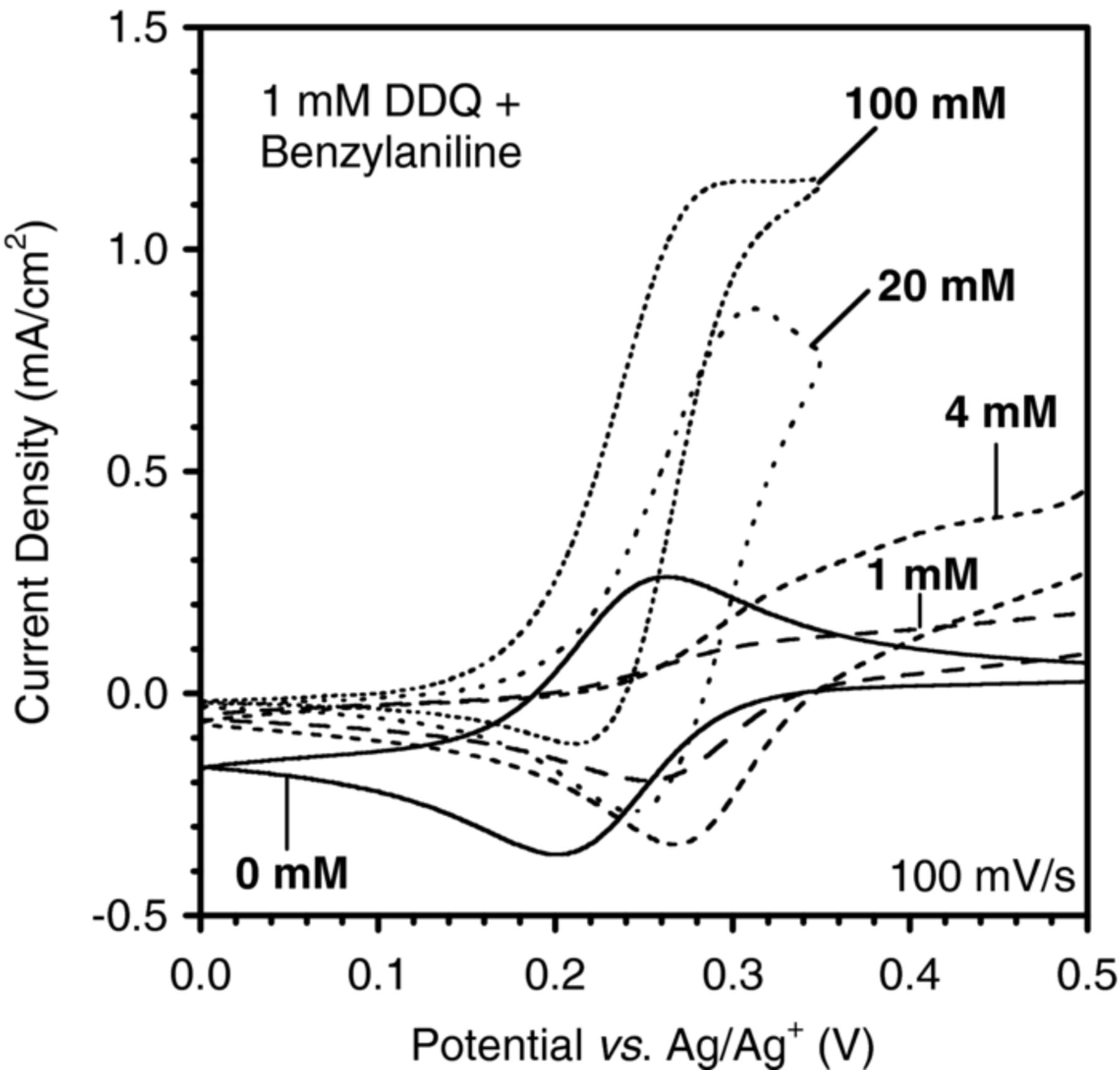
Figure 4. CVs of DDQ (1 mM) with different benzylaniline concentrations added.
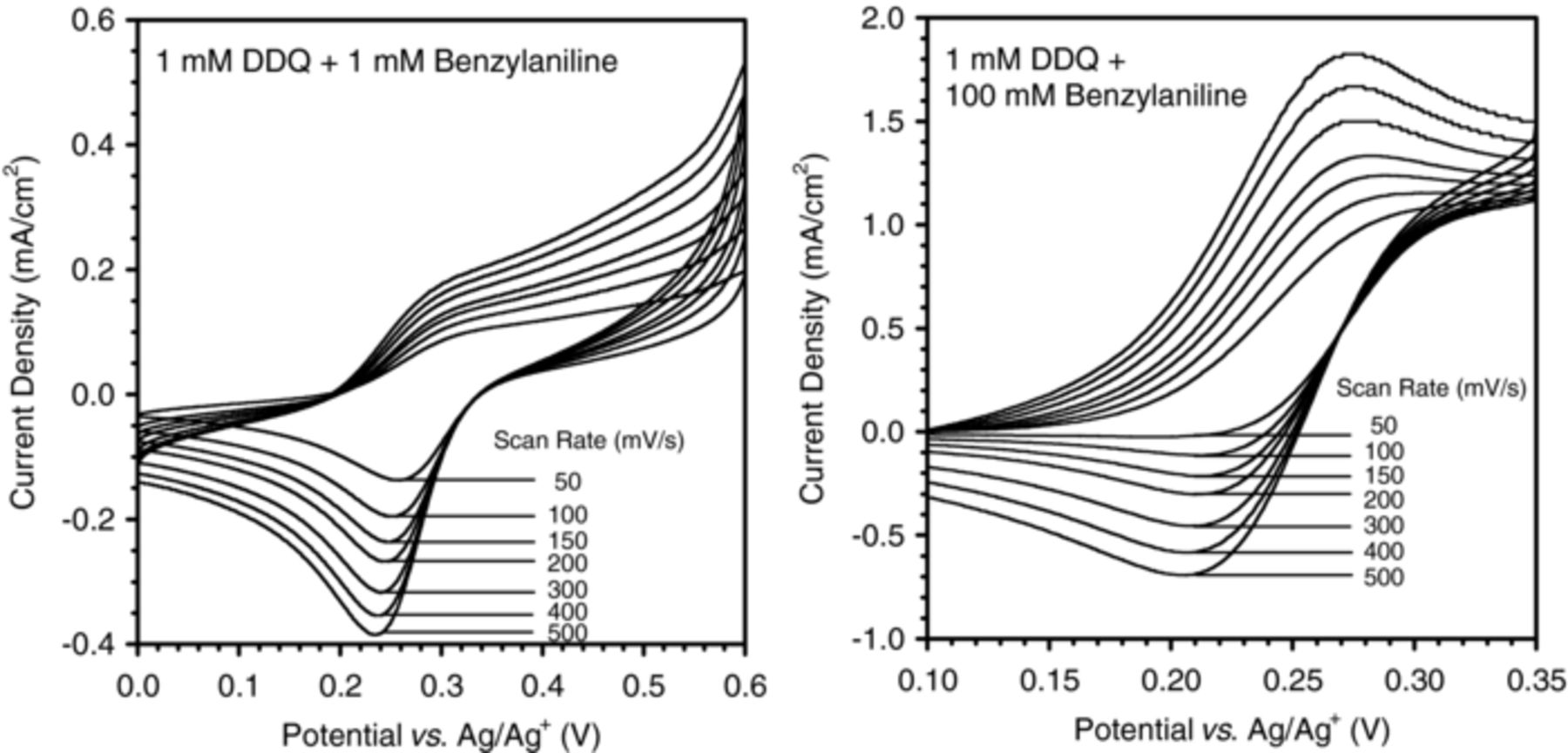
Figure 5. Scan rate dependence of DDQ with 1X benzylaniline (left) and 100X benzylaniline (right).
Rate constants were estimated from these results as described in the experimental section and are presented as log k (M−1·s−1) in Table I. Experiments with added base (2,6-lutidine) were also performed and the corresponding rate constants are provided. As shown in Figure 4 above, at low fuel/catalyst ratios with no base present there is no increase in current at the DDQ redox potential, so the catalytic current could not be determined for these two situations.
Table I. Rate constants (log k(M−1s−1)) estimated from DDQ/benzylaniline experiments (no base, top; with 0.1 M lutidine, bottom). The concentration of DDQ used was 1 mM and the measured rate constants are for different concentrations of substrate benzylaniline listed.
| Scan Rate | 1 mM | 4 mM | 20 mM | 100 mM |
|---|---|---|---|---|
| 50 | 2.1444 | 1.7619 | ||
| 100 | 2.3179 | 1.7404 | ||
| 150 | 2.4340 | 1.8265 | ||
| 200 | 2.5215 | 1.8690 | ||
| 300 | 2.6751 | 1.9701 | ||
| 400 | 2.7850 | 2.0425 | ||
| 500 | 2.8594 | 2.0644 | ||
| Scan Rate | 1 mM | 4 mM | 20 mM | 100 mM |
| 50 | 2.7444 | 2.5119 | 2.3244 | 3.8619 |
| 100 | 3.1654 | 2.7829 | 2.4679 | 4.0129 |
| 150 | 3.1165 | 2.6890 | 2.4565 | 3.9265 |
| 200 | 3.2790 | 2.8515 | 2.4915 | 3.9615 |
| 300 | 3.4701 | 2.8551 | 2.5926 | 4.0101 |
| 400 | 3.7450 | 3.0625 | 2.7400 | 4.1050 |
| 500 | 3.7819 | 3.1594 | 2.8369 | 4.1044 |
As mentioned previously, one of the confirmations that the kinetics of the system are appropriate for case 1 (where reaction 3 is much faster than reverse reaction 2 (see kinetics section above), is that icat/ioγ increases with increasing catalyst or fuel concentration. This was noted to only be the case for increasing the fuel concentration from 20 to 100 mM with base present. In all of the other situations the value of icat/ioγ decreased as more fuel was added (catalyst concentration was constant). This observation also indicates that there are likely two different things going on depending on the catalyst/fuel ratio.
Only one catalyst concentration was used in these experiments so any dependence on Cp cannot be determined at this point. If the rate constant was also independent of γ (ratio of fuel to catalyst) and υ (scan rate) then the values of k in the tables above should all be the same, which is not the case. It is noted, however, that the values of log k calculated for 1 mM DDQ with high benzylaniline concentrations for all scan rates are all very close taking into account experimental error. It appears that the kinetics of the system follow case 1 when a large amount of fuel is present, but not when the concentration is significantly lower.
The catalytic activity observed for DDQ/benzylaniline in the presence of large excess of substrate is consistent with an outer-sphere mechanism controlled by the potential difference between catalyst and substrate. When a base is present the rate at which a proton is lost from the radical cation is increased, which in turn accelerates redox catalysis. However, interactions between the catalyst and base or the fuel and base complicate the determination of catalytic current. Results for DDQ/benzylaniline demonstrate different mechanisms between a 1:1 catalyst/fuel ratio and a large excess of fuel. The stoichiometric results are consistent with the formation of a charge transfer complex that facilitates hydride transfer, while the results with a large excess of fuel indicate formation of the radical anion of DDQ. These experiments demonstrate how the conditions of the electrolysis can alter the mechanism and hence the course of the reaction, an important consideration for coulombic efficiency in an energy device. A future paper will report on the preparative electrolysis results with a large excess of benzylamine over DDQ as well as in the presence of ferrocene catalyst.
Ferrocene
Ferrocene was examined as a redox catalyst for the two model substrates, indoline and benzylaniline. Although the catalysis is weak with indoline as the fuel, catalytic current can be observed at low fuel/catalyst ratios (1 to 20 X fuel) in the absence of base (Figure 6, left). Conversely, in the absence of base, no catalysis was observed when benzylaniline was used as the fuel and this system required an excess of base (imidazole) and larger fuel/catalyst ratios (40 to 100X) to observe significant catalytic current, (Figure 6, right).
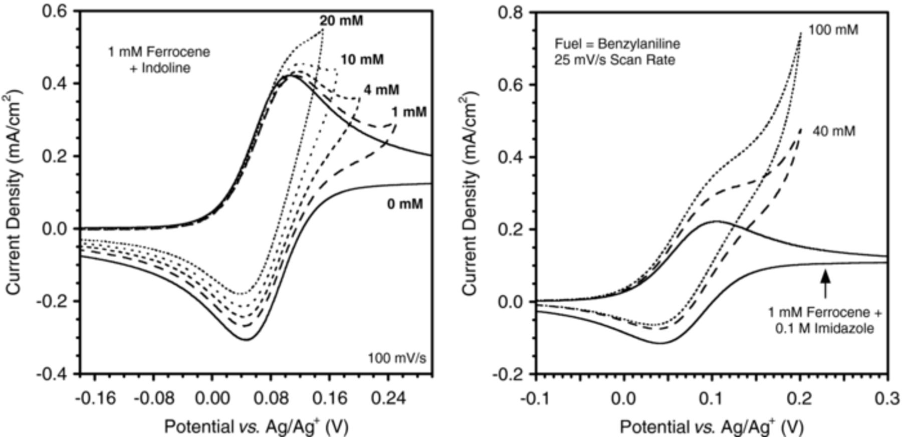
Figure 6. Catalytic current is observed in the absence of base with indoline as the fuel (left), however an excess of base (imidazole) is needed to achieve catalysis with benzylaniline as the fuel (right).
The observed catalytic behavior can be attributed to the difference between the redox potential of the catalyst (ferrocene) and the oxidation potential of the fuel at the electrode. According to Marcus Theory, for outer sphere electron transfer to occur at measurable rates the potential difference must be less than about 400 to 500 mV. As shown in Figure 7, benzylaniline oxidizes at a potential about 500 mV more positive than the ferrocene redox potential, while indoline is only about 250 mV more positive. These results therefore indicate that the catalytic activity observed for ferrocene/indoline is due to outer sphere electron transfer by a mechanism consistent with equations 1–3 above. The addition of base such as imidazole or 2,6-lutidine results in a negative shift of the peak potential and an increase in the peak currents which is consistent with change from a one electron dimerization process to a two electron dehydrogenation. For ferrocene/benzylaniline, there are two possibilities. One is that outer sphere electron transfer is occurring by an ECE mechanism, but the rate is very slow in the absence of base (so that no catalytic current is observed under these conditions). As previously mentioned, the first deprotonation step drives catalysis and therefore adding base will speed up this step and consequently increase the rate of electron transfer, resulting in more catalytic current. Another possibility is that the base is deprotonating (or partially deprotonating) the fuel to its conjugate base, which then transfers an electron to the catalyst, resulting in outer sphere electron transfer by a CEE mechanism.21
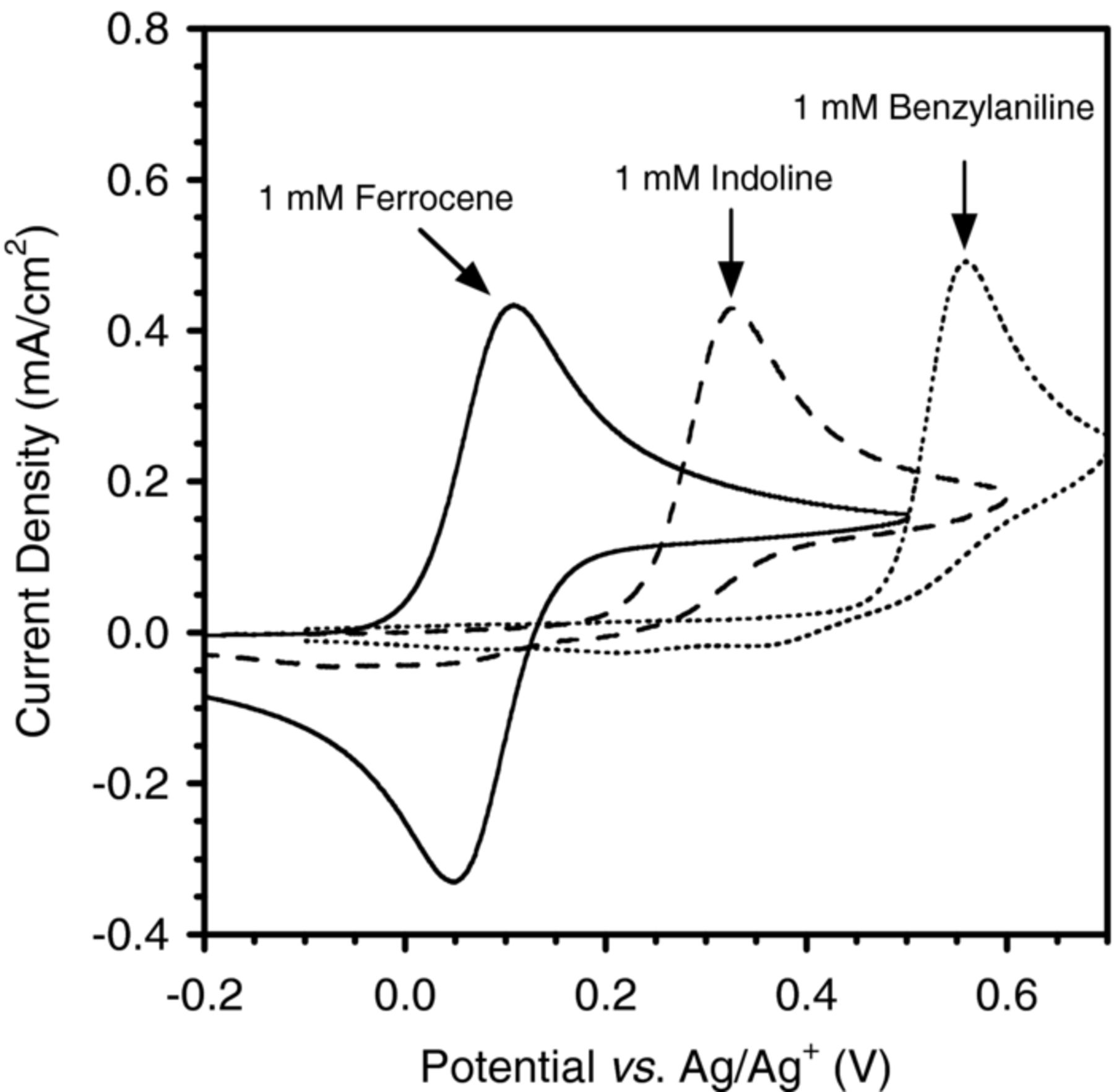
Figure 7. Plot showing the difference in oxidation potential between the catalyst (ferrocene) and the two substrates (indoline and benzylaniline).
Decamethylferrocene
Decamethylferrocene catalyzes the dehydrogenation of indoline as shown in Figure 8. In the absence of base no reaction is observed between the catalyst and indoline. A reaction is only observed with 1,1,3,3-tetramethylguanidine (or diethylenetriamine, not shown) added as base; weaker bases such as imidazole and triethylamine resulted in no reaction. The increase in current at the ferrocene redox potential when the catalyst, fuel, and base are combined indicates catalysis. This is consistent with a CEE mechanism where a pre-equilibrium exists between the fuel and its conjugate base, which then transfers an electron to the oxidized form of the catalyst.21
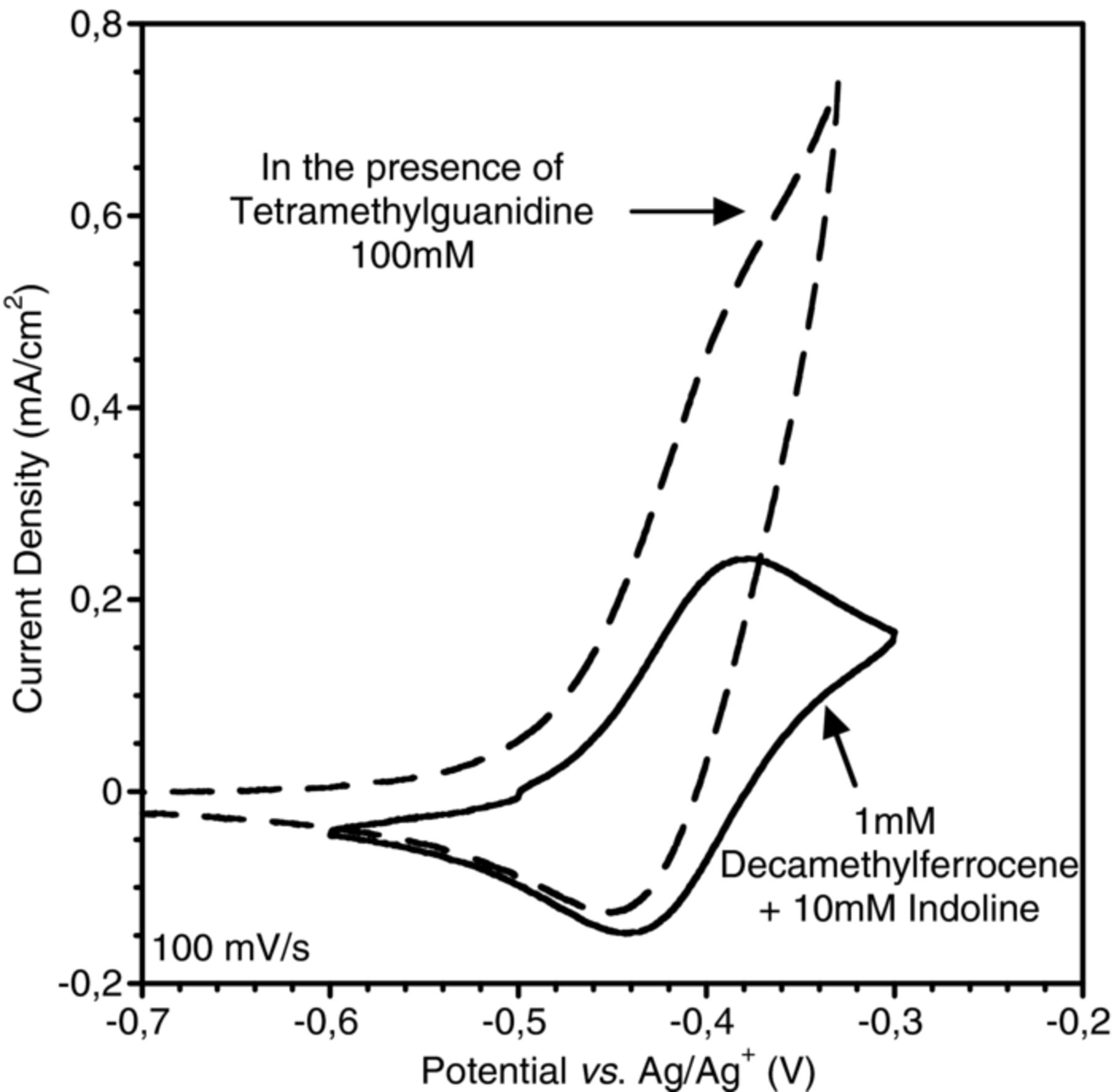
Figure 8. CVs showing decamethylferrocene catalyzed dehydrogenation of indoline.
Controlled potential electrolyses were carried out on indoline (10 mM) in acetonitrile in the presence of tetramethylguanidine using a carbon felt electrode in a stirred, two-compartment cell. The products of the electrolyses were identified using GC/MS and quantified by HPLC. In the absence of added base the applied potential was +0.38 V and the yield of indole was less than 10% while in the presence of base the applied potential was +0.1 V. When decamethylferrocene was added to the solution with base present current could be passed at −0.38 V. The yields of indole are given in Table II along with the conversion and electron equivalents passed. The undesired products have been identified as dimeric compounds which are more easily oxidized than the substrate indoline leading to polymeric products which have been detected by use of Gel Permeaation Chromatography. It has also been noted that the acetonitrile solvent can become involved in the reaction leading to a complicated product distribution.25
Table II. Controlled potential electrolyses of indoline (10 mM) in 0.1M Et4N BF4/acetonitrile plus 1,1,3,3-tetramethylguanidine (100 mM) at a carbon felt working electrode. Potential was −0.39 V vs. Ag/0.1M Ag+ in presence of catalyst, 0.1 V vs. Ag/0.01M Ag+ in the absence of catalyst. The number of electrons/molecule were calculated by measurement of the charge passed during the electrolysis and dividing by the number of moles of substrate.
| Conversion | Indole yield | Number of e−/molecule | |
|---|---|---|---|
| no catalyst | 70% | 12% | 2.2 |
| 1 mM catalyst | 87% | 16% | 2.1 |
| 2 mM catalyst | 97% | 14% | 3.9 |
| 3 mM catalyst | 88% | 51% | 3.6 |
| 5 mM catalyst (T 40°C)* | 100% | 51% | 5.9 |
The results in Table II show that an increase in the relative concentration of the decamethylferrocene leads to greater yield of the dehydrogenation product and this is consistent with a CEE mechanism (see Scheme 2). A possible competing reaction would involve a CE reaction to yield a neutral radical that undergoes dimerization in a similar fashion to a Kolbe reaction. The higher concentration of catalyst could cause the electron transfer reaction to compete more effectively with the dimerization. A number of dimer products have been isolated and identified and more detailed description will be given in future reports which will facilitate a more detailed examination of the mechanism of oxidation. However, it is noted that use of the decamethylferrocene catalyst at negative electrolysis potentials appears to avoid further oxidation of the dimers leading to a somewhat simpler product distribution.
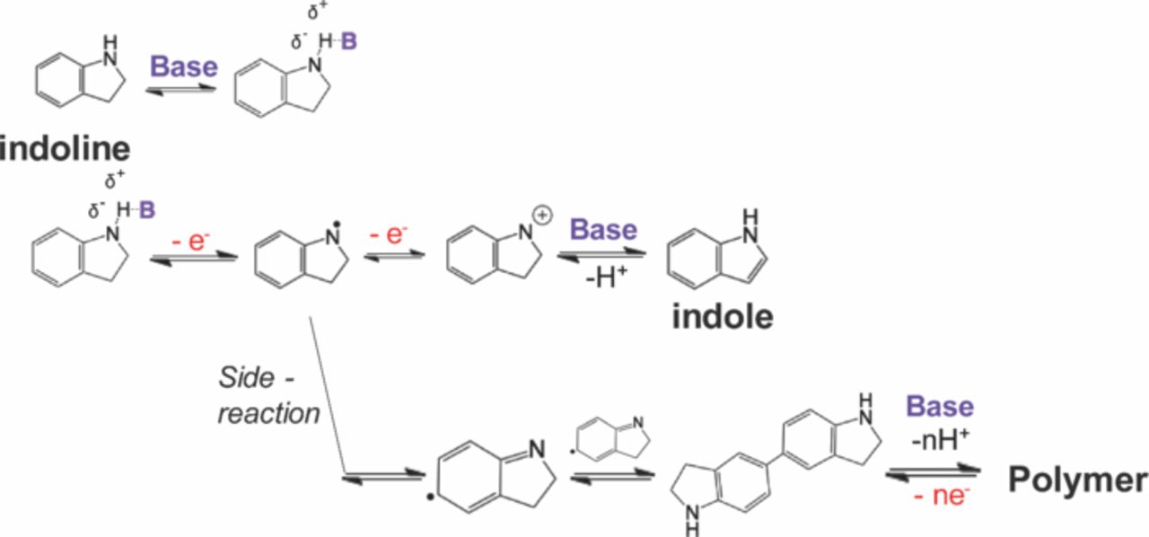
Scheme 2. Possible mechanism for oxidation of indoline in the presence of base.
A recent report13 has described the potential participation in the reaction of hydrogen–bonded complexes between the indoline and the added base. Scheme 2 incorporates such complexes but does not exclude the possibility that such complexes are in equilibrium with the conjugate base of the fuel in a step wise mechanism rather than a concerted proton-coupled electron transfer. More detailed measurements on this matter will be reported shortly. However, the use of the decamethylferrocene as an electron transfer catalysts demonstrates that the operating potential of the electrode can be lowered to values compatible with an operating fuel cell and that the course of the reaction may be guided to yield the coulombic efficiencies necessary for an energy conversion device.
Conclusions
Ferrocene and quinone derivatives were used to catalyze and lower the overpotential of dehydrogenation of two model substrates, N-benzylaniline and indoline. Outer sphere electron transfer by either an ECE or CEE mechanism (depending on the catalyst/fuel/base combination) was shown to be the likely catalytic mechanism for large excess fuel concentrations based on cyclic voltammetry measurements and rate constant estimations. Quinone catalysts appear to operate via a hydride transfer mechanism under stoichiometric conditions. These types of experiments can be used to screen potential catalyst/fuel combinations and optimize the underlying chemical reactions for an energy storage system that uses an organic liquid as a virtual hydrogen storage medium. The experiments described here demonstrate that a considerable amount of optimization will be required to produce efficient dehydrogenation reactions at practical voltages for fuel cell operation. However, these initial experiments are carried out in relatively uncontrolled, batch reactions and there remains much room for improvement through the use of continuous flow cells and membrane electrode assemblies. The use of membrane electrode assemblies that are commonly used in PEM fuel cells will provide a route to eliminate the use of co-solvents and electrolytes that will allow the use of neat fuels such as the dodecahydro-N-ethylcarbazole shown in Figure 1. Preliminary experiments using such approaches have been attempted10 with predictably poor results, demonstrating the challenges to be overcome. The results reported here are initial steps in approaching parts of the problem in a measured, stepwise and logical fashion. Experiments concerning the use of the more advanced engineering systems will be reported on in due course as well as the use of more complex, energy-rich fuels.
Acknowledgments
This material is based upon work supported as part of the Center for Electrocatalysis, Transport Phenomena, and Materials (CETM) for Innovative Energy Storage, an Energy Frontier Research Center (EFRC) funded by the U.S. Department of Energy, Office of Science, Office of Basic Energy Sciences under Award Number DE-SC00001055 and under DOE Contract No DE-AC02–05CH11231.
