Abstract
Strategies are presented to enhance operating potential and cycle life of AC/AC capacitors using salt aqueous electrolytes. Li2SO4 (pH = 6.5) allows 99% efficiency to be exhibited at 1.6 V cell potential with low self-discharge, while in BeSO4 (pH = 2.1) efficiency is low (81%). Li2SO4 performs better due to high di-hydrogen over-potential at the negative electrode and related pH increase in AC porosity. When stainless steel current collectors are used in Li2SO4, the cell resistance suddenly increases after 12 hours floating at 1.6 V, due to corrosion of the positive collector. With nickel negative and stainless steel positive collectors, the electrode potentials are shifted by −105 mV at cell potential of 1.6 V, allowing stable cell parameters (capacitance, resistance) and reduction of corrosion products formation on positive steel collector after 120 hours floating. Phenanthrenequinone was grafted on activated carbon to get an additional faradaic contribution in buffer solutions (pH = 4.0 or 7.2). The three-electrode cell CVs show that the redox peaks of the phenanthrenequinone graft shift toward negative values when pH increases from 4 to 7.2. The grafted carbon displays a capacitance value of 194 F g−1 at pH = 4.0 as compared to 82 F g−1 for the as-received carbon.
Export citation and abstract BibTeX RIS

This is an open access article distributed under the terms of the Creative Commons Attribution 4.0 License (CC BY, http://creativecommons.org/licenses/by/4.0/), which permits unrestricted reuse of the work in any medium, provided the original work is properly cited.
Electrical double-layer capacitors (EDLCs) based on activated carbons (AC) and traditional aqueous electrolytes, such as H2SO4 and KOH, operate at low cell potential (up to ∼0.8 V), limiting their capability at industrial level.1–4 In order to improve the energy (E = ½ CU2), both capacitance (C) and cell potential (U) determined by the stability window of the electrolyte have to be optimized. In this context, it has been recently demonstrated that symmetric capacitors based on AC electrodes and salt aqueous electrolyte (0.5 mol L−1 Na2SO4) exhibit excellent cyclability under galvanostatic charge/discharge up to 1.6 V.5,6. While using 1 mol L−1 Li2SO4 and gold current collectors, excellent cycle life has been shown up to ∼1.9 V using galvanostatic charge/discharge.7,8 Such high cell potential value is caused by a high over-potential for di-hydrogen evolution as a consequence of water reduction and OH− ions generation in the porosity of the negative AC electrode.5,7 According to the Nernst equation (Ered = −0.059 pH), the pH increase associated to OH− ions causes locally a shift of redox potential to lower values. Based on this fact, it has been recently demonstrated that the di-hydrogen evolution over-potential is higher in almost neutral electrolyte solutions (pH = 4–8) than in acidic ones, resulting in larger operating cell potential of asymmetric capacitors in the former media.9 From the foregoing, it makes sense to study in more details the influence of aqueous electrolyte pH on the electrochemical performance of AC/AC capacitors beyond only the cell potential.
Besides, when shifting from gold to stainless steel current collectors in order to develop low cost AC/AC capacitors in 1 mol L−1 Li2SO4, constant capacitance and low cell resistance have been observed during potentiostatic floating at cell potential of 1.5 V, while capacitance drops and resistance increases continuously if the floating potential is raised to 1.6 V.10,11 The increase in resistance has been attributed to i) oxidation of the positive AC electrode owing to irreversible oxygen production and/or ii) generation and accumulation of stainless steel corrosion products (as the positive electrode potential is higher than the water oxidation limit) at the current collector/electrode interface, both impeding the cell performance. In order to overcome this issue, 0.1 mol L−1 Na2MoO4 has been used as additive to 1 mol L−1 Li2SO4, allowing the operating potential of the positive electrode to be shifted below the thermodynamic water oxidation limit. As a consequence, sodium molybdate prevents from corrosion of the positive current collector, enabling constant low cell resistance and high capacitance during potentiostatic floating at 1.6 V for 120 hours.12 Active material coatings on metallic foil have been further employed in order to eliminate the possible deposition of a resistive layer at the active material/current collector interface when self-standing AC electrodes are used in physical contact with the current collectors. Accelerated ageing by floating has been applied to verify the long term stability of the cells prepared with this strategy.13 Upon floating AC/AC cells in 1 mol L−1 Li2SO4 for 120 hours at 1.6 V, the cell resistance increased by 136% with self-standing electrodes and only by 93% when coated electrodes were used.14 Another tactics could be to replace stainless steel by nickel current collectors. Indeed, due to its good stability and easy availability, nickel is a widely used electrode material for e.g., water electrolysis15 and was also found in this study as a proper collector to improve the performance of carbon/carbon capacitors in 1 mol L−1 Li2SO4.
Various strategies based on pseudo-capacitive or faradaic contributions have been reported to enhance the capacitance of carbon/carbon capacitors in aqueous media. Such contributions were obtained by i) adding electrochemically active species such as quinones16 and alkali metal iodides17–19 in the electrolyte, ii) using carbon electrode materials undergoing redox reactions resulting from naturally occurring surface functionalities, hydrogen storage and chemically/electrochemically grafted active molecules such as quinone derivatives.20–26 The later modification is generally realized by electrochemical27,28 or chemical29–31 reduction of diazonium cations. The pH of the applied electrolyte has a significant influence on the possible redox mechanisms involving proton and electron transfer,31–33 and consequently on the capacitance properties of quinone-modified carbons. Surface functionalization enables an increase of the specific capacitance of the modified electrode even by a factor of two compared to the pristine carbon electrode in acid and basic aqueous electrolytes. For example, the attachment of anthraquinone groups to the surface of the Black Pearl 2000 carbon enhanced the capacitance from 100 F g−1 for the unmodified carbon to 195 F g−1 for grafted carbon in 0.1 mol L−1 H2SO4.34 However, the highly corrosive character of H2SO4 in presence of most metallic current collectors imposes using less corrosive media, such as neutral electrolytes.
The present work aims at developing strategies to improve cell potential (U) and/or capacitance (C) of AC/AC electrochemical capacitors in salt aqueous electrolyte at room temperature. This will be realized by i) determining the influence of salt aqueous electrolyte pH on the maximum potential window of the capacitor; ii) replacing steel (−)/steel (+) current collectors by nickel (−)/nickel (+) or nickel (−)/steel (+); iii) modifying the carbon electrode materials by quinone species exhibiting pseudocapacitive contributions.
Experimental
Materials and chemicals
The commercial activated carbons DLC SUPRA 30 (Norit, SBET = 2066 m2 g−1, Vmicro = 1.04 cm3 g−1, average micropore size L0 = 1.16 nm) and YP 80F (Kuraray Chemicals Co, SBET = 2270 m2 g−1, Vmicro = 0.99 cm3 g−1, average micropore size L0 = 1.17 nm) were used for manufacturing pellet and coated electrodes, respectively. 9,10-phenanthrenequinone (Sigma-Aldrich, 95%) and tert-butyl nitrite (Sigma-Aldrich, 90%) were used for the modification of activated carbons. The aqueous electrolytes were based on lithium sulfate (Li2SO4.H2O, Sigma-Aldrich, >99%), sodium sulfate (Na2SO4, Sigma-Aldrich, >99%), potassium sulfate (K2SO4, Avantor, 99%), magnesium sulfate (MgSO4.7H2O, Avantor, 98%), aluminum sulfate (Al2(SO4)3.18H2O, Avantor, 98%) and beryllium sulfate (BeSO4.4H2O, Sigma-Aldrich, >99%). Di-sodium hydrogen phosphate (Na2HPO4, Sigma-Aldrich, >99%) and sodium di-hydrogen phosphate (NaH2PO4, Sigma-Aldrich, >99%) were used to prepare buffer solutions.
Carbon modification by grafting
Carbon modification was carried out by grafting according to the procedure described in reference35 using spontaneous reduction of in-situ generated diazonium cations. 2-amino-9,10-phenanthrenequinone (186.3 mg, 0.1 equiv. compared to carbon) was added to acetonitrile (300 mL), and the solution was stirred until complete dissolution of the quinone derivative. Then, tert-butylnitrite (99 μL, 1 equiv. compared to quinone) was added to the solution, the mixture was stirred for 15 min and the DLC Supra 30 activated carbon (100 mg) was added. Thereafter, 1 equiv. of tert-butylnitrite was added two more times (after 30 minutes and 1 hour) directly to the organic suspension, and the mixture was kept at ambient temperature overnight under stirring. The modified carbon powder was finally collected by vacuum filtering on a nylon filtration membrane having a pore size diameter of 0.47μm (Pall) and washed by successive aliquots of acetonitrile, DMF, acetone and methanol in order to remove any unreacted species from the surface. Afterwards, the modified carbon was dried under vacuum overnight at 60°C; in the following part of the manuscript, this carbon will be referred to as DLC Supra 30-PQ.
Physicochemical characterization of carbons
The surface oxygenated functionality of as-received and grafted carbons was characterized by temperature-programmed desorption (TPD), using a TG equipment (TG209 F1 Iris, NETZSCH) coupled with a mass spectrometer (QMS 403C Aëolos, NETZSCH). In these experiments, ca. 6 mg of carbon powder was heated up to 950°C (heating rate 20°C min−1) under helium flow rate of 50 mL min−1. CO2- and CO-evolving groups were quantified after calcium oxalate monohydrate calibration, taking into account CO disproportionation.36
The porous texture of carbons was determined from nitrogen adsorption/desorption isotherms recorded at −196°C using an ASAP 2020 (Micrometrics). Prior to the measurements, the samples (around 60 mg) were degassed under vacuum for 12 h at 350°C for as-received carbons and 24 h at 110°C for grafted carbons. The pore size distribution (PSD) was determined using the quenched solid density functional theory (QSDFT),37 and the total pore volume Vtotal as well as micro Vmicro and mesopore volumes Vmeso were obtained directly from the calculated cumulative PSDs. The average micropore size (L0) was determined from the integration of the PSD area for pores below 2 nm. The static contact angle for as-received and grafted carbons was determined using a video-based optical contact angle measuring instrument OCA 15Pro (DataPhysics Instruments, Germany).
Cells construction and electrochemical investigations
Self-standing pellet electrodes were prepared by mixing as-received or grafted (DLC Supra 30-PQ) carbon (80 wt%) with 10 wt% poly(tetrafluoroethylene) (PTFE - 60 wt% dispersion in water, Sigma-Aldrich) binder and 10 wt% carbon black (Super C65, Timcal) conductivity enhancer. The three components were mixed in isopropanol (Avantor, 99.5%) until a dough was obtained; then the dough was rolled into sheet and dried under vacuum at 110°C (as-received carbon) and 60°C (DLC Supra 30-PQ carbon) for 12 hours. 10 mm diameter (8–10 mg) pellet electrodes of thickness ∼0.2 mm were punched out from the sheet, and AC/AC capacitors were realized by sandwiching a porous glass microfiber membrane GF/A (Whatman, thickness = 0.26 mm) between two pellet electrodes and stainless steel 316L current collectors, using PTFE Swagelok-type vessels with or without inlet for a reference electrode. In order to avoid the issues related with conductivity as well as wetting with the electrolyte, electrodes of same mass and thickness were used. Hg/Hg2SO4 in 0.5 mol L−1 H2SO4 was used as reference electrode for studies on as-received carbons, and a silver wire as quasi-reference electrode for cells with DLC Supra 30-PQ carbon. The solutions used in cells with as-received carbons were 0.5 mol L−1 K2SO4 and 1 mol L−1 Li2SO4, Na2SO4, MgSO4, BeSO4, and Al2(SO4)3. The pH and conductivity values of these electrolytes are given in Table I. In case of cells built from the DLC Supra 30-PQ carbon, the electrolyte was a buffer solution, either 0.1 mol L−1 phosphate buffer (pH = 7.2) in deionized water, or a commercial biphthalate buffer (pH = 4.0) purchased from Metrohm.
Table I. pH and conductivity values of the salt aqueous electrolytes measured at 24°C, each with a concentration of 1 mol L−1 except for K2SO4 (0.5 mol L−1) due to solubility limitations.
| Electrolyte | Li2SO4 | Na2SO4 | K2SO4 | MgSO4 | Al2(SO4)3 | BeSO4 |
|---|---|---|---|---|---|---|
| pH | 6.5 | 6.5 | 6.1 | 6.2 | 2.9 | 2.1 |
| Conductivity (mS cm−1) | 64 | 68 | 70 | 48 | 36 | 32 |
For realizing coated electrodes, the surface of grade 1.431 stainless steel (Interbelts, thickness = 15 μm) and nickel (Schlenk, thickness = 20 μm) foils was pre-coated with a thin layer (15 μm) of carbon conductive ink (Electrodag PF-407A, Acheson) to provide a rougher substrate. Activated carbon YP 80F (83.5 wt%), carbon black (Super C65, Timcal, 8.5 wt%) conductivity enhancer and polyvinylidene difluoride (PVdF, Kynar HSV 900, Arkema, 8 wt%) binder dissolved in 1-methyl-2-pyrrolidone (NMP, Sigma-Aldrich) were mixed with an homogeneizer (IKA Ultra-Turrax T 18 basic), and the obtained slurry was cast with a Doctor Blade applicator (Elcometer 3600) on the previously prepared surface of stainless steel or nickel foil. Afterwards, the coating was dried by slow evaporation in air overnight, followed by heating under vacuum at 120°C for 12 hours. 10 mm diameter disk electrodes (mass of active material ∼3.5 mg, coating thickness ∼100 μm) were punched out from the coated foil. AC/AC capacitors were realized in PTFE Swagelok-type vessel (with additional inlet for Hg/Hg2SO4 reference electrode) by sandwiching an absorptive glass mat separator (AGM, Bernard Dumas, thickness = 0.52 mm) between two coated electrodes and cylindrical current collectors, either from stainless steel or nickel. Before being closed, the assembled system was soaked under vacuum with 1 mol L−1 Li2SO4 electrolytic solution.
The electrochemical performance of the two-electrode (without and with reference) and three-electrode cells was determined with a VMP3 (Biologic, France) multichannel potentiostat/galvanostat. The gravimetric capacitance C (F g−1 of as-received as well as DLC Supra 30-PQ activated carbons in one electrode) was estimated from galvanostatic discharge at 0.2 A g−1 and cyclic voltammetry at scan rates of 2 mV s−1 and 5 mV s−1. Accelerated ageing of the cells was realized as reported in Ref. 9 by a succession of two-hour potentiostatic floating periods, each followed by five galvanostatic (1 A g−1 referred to the active mass of one electrode) cycles the cell potential hold during floating and the maximum cell potential during galvanostatic cycling were fixed at the same value. The capacitance and cell resistance were estimated from the fifth discharge to monitor the state of health (SOH) after each floating period. The test sequences were repeated 60 times, for a total floating time of 120 h. A digital pressure sensor Keller 35X Ei was connected to the capacitors in 1 mol L−1 Li2SO4 or BeSO4 to monitor gas evolution.
Results and Discussion
Effect of electrolyte pH on the performance of AC/AC cells
In this section, self-standing electrodes made from as-received DLC Supra 30 (further named AC) and stainless steel (grade 316L) current collectors were used. In our previous reports, we demonstrated that oxidation of the positive AC electrode and corrosion of the positive current collector are essentially the cause of performance deterioration during floating of AC/AC capacitors in 1 mol L−1 Li2SO4 at 1.6 V.11 According to the Nernst equation, the thermodynamic limits for di-oxygen and di-hydrogen evolution at the positive and negative electrodes, and consequently the possible performance degradation, are pH dependent and given by the equations Eox = 1.23 − 0.059 pH and Ered = −0.059 pH vs SHE, respectively. In other words, the operating potential ranges of positive and negative electrodes in aqueous based capacitor systems are controlled by the electrolyte pH. For this reason, we have determined the electrochemical performance of the activated carbon DLC Supra 30 (AC) in cells using the various sulfate salt solutions listed in Table I.
Fig. 1 shows the three-electrode cyclic voltammograms (CV) of AC in 1 mol L−1 Li2SO4 and 1 mol L−1 BeSO4. When the scans are realized at potential higher than the water reduction limit (−0.383 V vs SHE in Li2SO4 and −0.124 V vs SHE in BeSO4), the CVs demonstrate only electrical double-layer charging in both electrolytes. By contrast, upon polarization toward potentials lower than the reduction limit at the considered pH, the performance of AC differs significantly in the two electrolytes. A negative current leap related with nascent hydrogen formation and chemisorption in the AC electrode38 starts to appear at potential lower than the limit, and it rapidly gives rise to important oscillations related with di-hydrogen bubbling in case of the cell in BeSO4, while such clearly visible oscillations are almost not observed with Li2SO4. Since the pH of bulk 1 mol L−1 Li2SO4 is close to neutrality (pH = 6.5), a low amount of OH− anions produced due to water reduction provokes a sudden pH increase inside the AC porosity to much higher values (after polarization of the cell, the pH measured on electrode surface is higher than 10), and it results in higher over-potential for di-hydrogen evolution. During CV experiments in 1 mol L−1 Li2SO4, the onset of oscillations attributed to di-hydrogen evolution starts at about −0.8 V vs SHE. Hence, the negative AC electrode in 1 mol L−1 Li2SO4 is capable of i) storing hydrogen produced through water reduction and ii) operating safely up to low potential owing to high local pH in the pores of AC. By contrast, in the acidic 1 mol L−1 BeSO4 solution (pH = 2.1), the pH within the AC porosity is almost not changed by the produced OH− during water reduction. Consequently, di-hydrogen evolution starts at −0.3 V vs SHE, very close to the thermodynamic reduction potential of water (Fig. 1b), and drives the negative AC electrode to perform in narrow potential range.9 The difference of over-potential for AC in the two electrolytes is even better seen during the anodic scan, where hydrogen stored in the AC porosity during the negative scan is oxidized, giving rise to a desorption peak. As it can be seen on Fig. 1, the polarization potential difference between the desorption peak and the thermodynamic water reduction potential is ∼0.78 V and ∼0.42 V in Li2SO4 and BeSO4, respectively. Hence, the desorption activation energy is higher in Li2SO4 than in BeSO4 medium.38
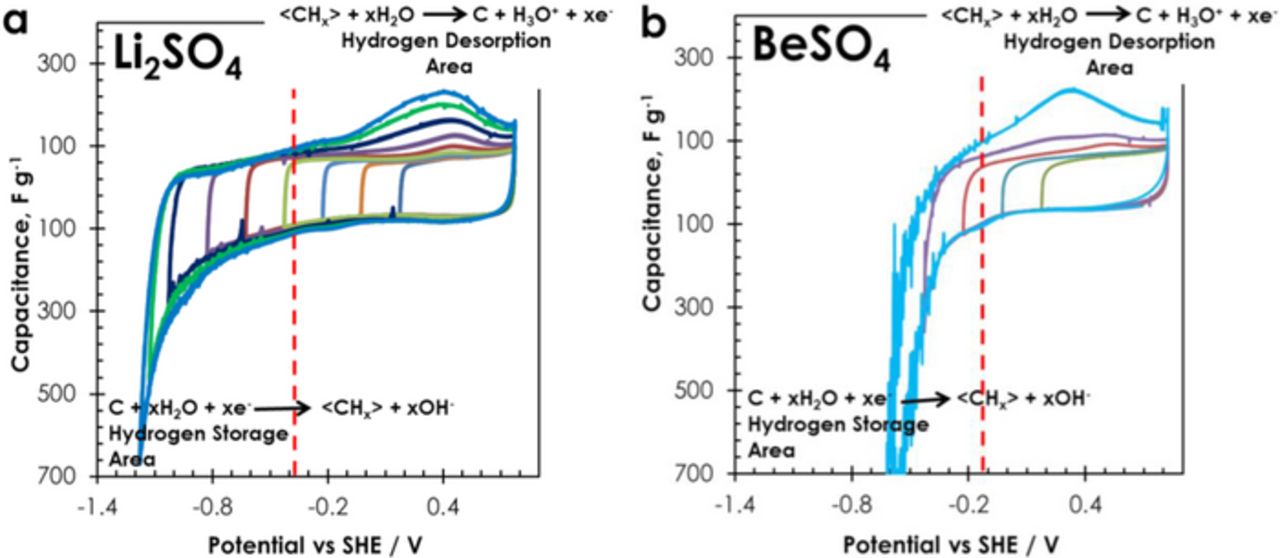
Figure 1. Three-electrode cyclic voltammograms (2 mV s−1) of AC obtained by stepwise decrease of the negative cutoff potential (a) in 1 mol L−1 Li2SO4 solution with pH = 6.5; (b) in 1 mol L−1 BeSO4 solution with pH = 2.1. The vertical dashed lines represent the theoretical water reduction potential at the considered pH.
The potential extrema of the positive and negative electrodes of AC/AC capacitors in 1 mol L−1 Li2SO4 and 1 mol L−1 BeSO4 with Hg/Hg2SO4 reference have been determined by galvanostatic cycling for cell potentials ranging from 0.8 V to 1.6 V (Fig. 2). The positive electrode of the capacitors in 1 mol L−1 Li2SO4 and in 1 mol L−1 BeSO4 operates below the water oxidation limit (marked by the upper dashed line) up to cell potentials of 1.4 V and 1.5 V, respectively. The potential range of the negative AC electrode itself is controlled by the lower dashed-line representing the practical di-hydrogen evolution determined from the previous three-electrode cell experiments. Consequently, in Li2SO4 electrolytes, the negative electrode works without any di-hydrogen production in all the considered cell potential range, while in case of BeSO4 the limit seems to be reached for a cell potential of 1.3 V. Hence, AC/AC capacitors in salt aqueous electrolytes can operate safely up to 1.6 V only when pH is close to neutrality.
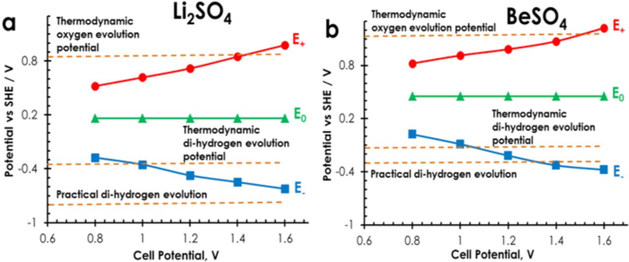
Figure 2. Potential limits of positive and negative electrodes vs cell potential during galvanostatic charge/discharge (200 mA g−1) of AC/AC capacitors (a) in 1 mol L−1 Li2SO4 and (b) in 1 mol L−1 BeSO4. E+ and E− represent the maximum and minimum potentials reached by the positive and negative electrodes, respectively. E0 corresponds to the rest potential of the electrodes at cell potential of 0 V.
In order to better evaluate the effect of different hydrogen evolution over-potential in the two electrolytes, a pressure sensor has been connected to AC/AC cells in 1 mol L−1 Li2SO4 and 1 mol L−1 BeSO4. Fig. 3a displays the evolution of gas over-pressure during a potentiostatic floating period of 6 hours at 1.4 V followed by 10 hours at open circuit, and confirms lower gas evolution in case of using Li2SO4 as electrolyte. Gas over-pressure in Li2SO4 reached 0.29 bar which is nearly half of 0.56 bar in case of BeSO4. Hence, due to different pH of the electrolytes, the over-potential for di-hydrogen evolution is different, resulting in different amount of di-hydrogen produced at the negative AC electrode. Consequently, the maximum cell potential of AC/AC capacitors with minimum gassing in salt aqueous electrolytes is controlled by the pH of the bulk solution, and reaches its higher value when the pH of the later is close to neutrality, allowing an important pH variation in the pores of carbon when small amounts of OH− ions are produced.
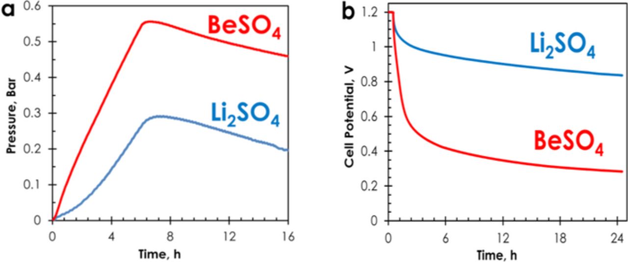
Figure 3. AC/AC cells in 1 mol L−1 Li2SO4 and 1 mol L−1 BeSO4: (a) gas overpressure during floating for 6 h at 1.4 V followed by OCV for 10 h, and (b) self-discharge profiles after polarization at 1.2 V for 30 minutes.
As shown in Fig. 3b, the redox reactions related with hydrogen generation at the negative electrode might also affect the self-discharge (cell potential evolution at open circuit) of the AC/AC cells in 1 mol L−1 Li2SO4 and 1 mol L−1 BeSO4. After a potentiostatic period of 30 minutes at 1.2 V, the self-discharge is definitely higher for the cell in BeSO4. Such high drop of cell potential in case of BeSO4 electrolyte might be related with the presence of impurities playing the role of shuttles;39,40 one might anticipate that some ions, in particular Fe2+ and Mn2+ are extracted from the stainless steel collectors at pH = 2.1.41,42
CVs of AC/AC capacitors in various sulfate aqueous electrolytes with different pH values are compared in Fig. 4a. The electrolytes with almost neutral pH values (Li2SO4, Na2SO4, K2SO4 and MgSO4) demonstrate nearly square shaped voltammograms, while in electrolytes with slightly acidic pH (BeSO4, pH = 2.1 and Al2(SO4)3, pH = 2.9) the CVs exhibit an important current leap at cell potential higher than ∼1.0 V during the positive scan. As discussed previously, such current increase is driven by i) higher hydrogen formation at the negative electrode than in case of neutral electrolytes and ii) surface functionalities formed by oxidation reactions on the positive AC electrode. It is noticeable that the CVs of capacitors with BeSO4 and Al2(SO4)3 are more deformed below 0.8 V on reverse scan as compared to those with neutral pH electrolytes, revealing more pronounced redox phenomena in slightly acidic pH; the latter are obviously associated with the important current leap observed at high cell potential in these electrolytes.
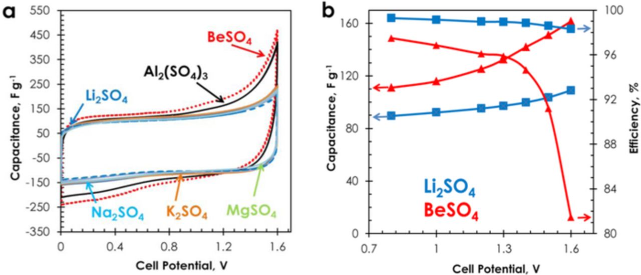
Figure 4. (a) Cyclic voltammograms (2 mV s−1) of AC/AC capacitors in various salt aqueous electrolytes, particularly displaying Li2SO4 (dashed line), BeSO4 (dotted line) and (b) capacitance and efficiency vs cell potential of the capacitors in 1 mol L−1 Li2SO4 and 1 mol L−1 BeSO4 determined from galvanostatic charge/discharge at 200 mA g−1.
The CVs realized up to 1 V revealed a pure EDL response in all the investigated sulfate electrolytes. As shown in Fig. 4b, the capacitance values obtained from galvanostatic discharge at cell potentials up to 1.0 V are much higher for capacitors with BeSO4 (and also Al2(SO4)3) than with Li2SO4 (and also the other sulfates with pH close to 6.5). The higher capacitance values in BeSO4 and Al2(SO4)3, despite the lower conductivity of these two electrolytes (Table I), may be related to the small ionic radii of Be2+ (0.031 nm) and Al3+ (0.050 nm) as compared to Li+ (0.060 nm), Na+ (0.095 nm), K+ (0.133 nm) and Mg2+ (0.065 nm). Indeed, assuming that ions are fully desolvated in the pores of AC,1 the application of formula C = ɛS/d, where d is the distance between the ions and the pore walls, suggests that the double-layer capacitance should be higher for the smallest ions Be2+ and Al3+ as compared to the other ions.
Hence, from the foregoing, two different behaviors were observed depending on local pH in carbon porosity and related over-potential for di-hydrogen evolution; 1 mol L−1 Li2SO4 and 1 mol L−1 BeSO4 electrolytes are representative of these different redox mechanisms. Fig. 4a shows that in all cell potential range, capacitance is much higher in BeSO4 than in Li2SO4 electrolyte, and it increases with cell potential due to the above afore mentioned pseudo-capacitive contributions.5 From 0.8 V to 1.6 V, the capacitance increases from 90 F g−1 to 108 F g−1 in Li2SO4 and from 111 F g−1 to 161 F g−1 in BeSO4. However, when the efficiency (ratio of discharge time/charge time during galvanostatic cycling) is expressed vs cell potential from 0.8 V to 1.6 V (Fig. 4b), one can observe an important drop from 97% to 81% in BeSO4, while it keeps at around 99% in all cell potential range with Li2SO4 electrolyte. The high drop of efficiency in BeSO4 at cell potential of about 1.3 V reveals that the faradaic processes (hydrogen generation/storage, formation of oxygenated functionalities by oxidation of the positive AC electrode) at the origin of higher capacitance in this electrolyte are highly irreversible. Consequently, the drop of efficiency together with the observed self-discharge in 1 mol L−1 BeSO4 precludes its application for AC/AC capacitors. Overall, the AC/AC capacitor based on 1 mol L−1 Li2SO4 performs up to 1.6 V with far better efficiency as compared to the one with 1 mol L−1 BeSO4. Data non presented in this report show that the AC/AC capacitors using all the other electrolytes with comparable pH (Na2SO4, K2SO4, and MgSO4) demonstrate good efficiency in all cell potential range from 0.8 V to 1.6 V; in case of Al2(SO4)3, the performance is the same as in BeSO4. Consequently, as far as the highest cell potential is researched, a pH slightly lower than 7 in the bulk electrolyte is a determining criterion for extending the operating cell potential range and for selecting this electrolyte for AC/AC capacitor.
Improvement of long time performance by coupling of different current collectors
In the previously presented experiments, the electrodes in the form of pressed pellets and sandwiching the separator were placed between two cylindrical current collectors. This kind of assembling differs from the industrial capacitors, where the electrodes are formed by casting the active layer on a metallic foil used as current collector. To further proceed in the optimization of the AC/AC capacitors in salt aqueous electrolyte, coated electrodes with YP 80F activated carbon (further named AC in all this part) have been realized in order to avoid the accumulation of trace amounts of decomposition products at the active material/current collector interface during accelerated ageing by potentiostatic floating.
Fig. 5 represents CVs of cells with stainless steel (Fig. 5a) and nickel collectors (Fig. 5b) in 1 mol L−1 Li2SO4 after every 40 hours of potentiostatic floating at 1.6 V. Whatever the collector, stainless steel or nickel, the CVs recorded on the fresh cells (black dashed line) display the typical rectangular shape for an electrical double-layer capacitor. By contrast, the CVs recorded after every 40 hours of floating at 1.6 V reveal a more resistive character for both types of collectors. However, for cells with stainless steel collectors, the capacitive current at cell potential higher than 1 V diminishes with the floating time, while it remains almost constant in case of nickel collectors (Inset in Fig. 5). This decrease of capacitive current reduces the energy density of the device at high cell potential and is most probably related to porosity saturation due to reduction of AC porosity by oxidation or/and corrosion products.10,11,12,43 After ageing, the presence of corrosion products is revealed by a russet color at the edges of electrodes and current collectors and on the separator; the formation of such products reduces the life-time of the device.
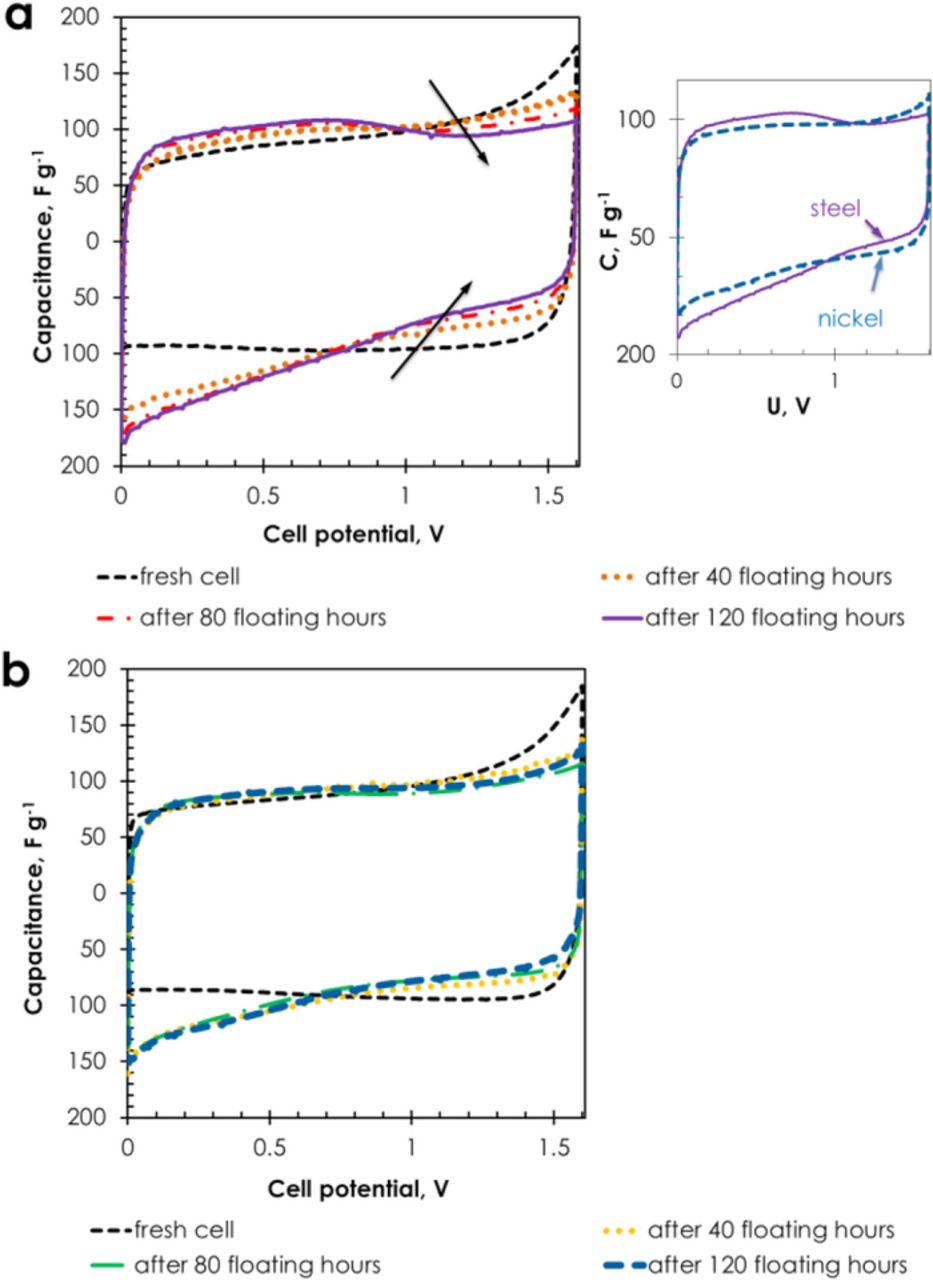
Figure 5. Cyclic voltammograms (5 mV s−1) recorded during floating at 1.6 V of AC/AC supercapacitors in 1 mol L−1 Li2SO4 with (a) stainless steel and (b) nickel collectors. The inset presents a comparison of the cells with stainless steel and nickel collectors after floating during 120 hours.
After accelerated ageing at 1.6 V, CVs of cells with nickel collectors did not show so pronounced narrowing as in the case of using stainless steel collectors. However, after opening the cell with nickel (−)/nickel (+) configuration, black and pale green residues were found on the separator and at the edges of the positive current collector, and pale green on the negative one. These residues are probably related to the observed pH increase to 7–8 on the surface of the positive electrode and to 10 on the negative one after 120 hours of floating. According to the values of electrodes potentials reached at cell potential of 1.6 V (E+ = 1.04 V and E− = −0.56 V vs SHE), and taking into account the Pourbaix diagram of nickel,44 these deposits can be attributed to +III and +IV (black) and +II (pale green) nickel states. However, as shown in Fig. 6 for the case of the capacitor with nickel (−)/nickel (+) collectors, the performance is not affected by the appearance of the deposits, and the cell resistance remains stable till the end of the test. For the capacitor with stainless steel (−)/stainless steel (+) current collectors, a sudden increase of resistance can be noticed after 12 hours of floating at 1.6 V, which probably contributes to the possible perturbation phenomena, i.e., evolution of gases, oxidation of carbon, formation of corrosion products.
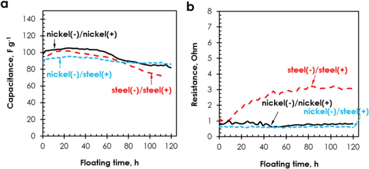
Figure 6. (a) Capacitance and (b) cell resistance evolution during floating at 1.6 V of AC/AC capacitors in 1 mol L−1 Li2SO4 with electrodes coated on stainless steel and nickel collectors.
Galvanostatic cycling realized at 1 A g−1 revealed the same discharge capacitance value of 85 F g−1 for the cells with stainless steel (−)/stainless steel (+) and nickel (−)/nickel (+) collectors. However, the positive electrode of the stainless steel (−)/stainless steel (+) cell displays a capacitance value of 125 F g−1, while the negative electrode of the nickel (−)/nickel (+) cell demonstrates 100 F g−1. Therefore, we decided to build an AC/AC system combining nickel and stainless steel as negative and positive collectors, respectively. Although, this combination did not improve the capacitance of the whole cell, Fig. 6 reveals that this cell presents a lower initial resistance value (0.6 Ω), and the most stable capacitance and resistance values during floating at 1.6 V. Once opening the cell after 120 hours of floating at 1.6 V, there was no corrosion of the positive current collector, although we could still notice green deposits on the negative one.
As shown in Fig. 7 displaying the CVs of both positive and negative electrodes separately, by using a two-electrode cell with reference electrode, the diminished corrosion of the positive stainless steel collector in the nickel (−)/stainless steel (+) system at 1.6 V could be explained by ca. −105 mV shift of the electrode potentials. In the figure, the vertical dashed lines represent the thermodynamic limit for di-oxygen evolution in 1 mol L−1 Li2SO4 (pH = 6.5) calculated from the Nernst equation (EO2 = 1.23 − 0.059 pH = 0.847 V vs SHE) and the experimental limit for di-hydrogen evolution (−0.8 V vs SHE). The value for H2 evolution was determined by observing the current oscillations on the three-electrode cyclic voltammograms, by analogy with the experiment done in the first part. Considering the nickel(−)nickel (+) system, the formation of deposits found on the separator and current collectors can be explained with help of Fig. 7a. At the negatively polarized electrode, the electrode surface pH increases up to 10, due to the formation of hydroxyl ions (H2O + e− → H + OH−),9 and the simultaneously produced nascent hydrogen is either chemisorbed on the carbon surface or combines to form di-hydrogen, provoking oscillations on the CVs (Fig. 7a).45 Water reduction results in an electrochemical OH− gradient allowing the chemical precipitation of Ni(OH)2 (green deposit) at potential E0 = 0.11 – 0.059 pH46 which is in agreement with the appearing current leaps below −0.48 V vs SHE.
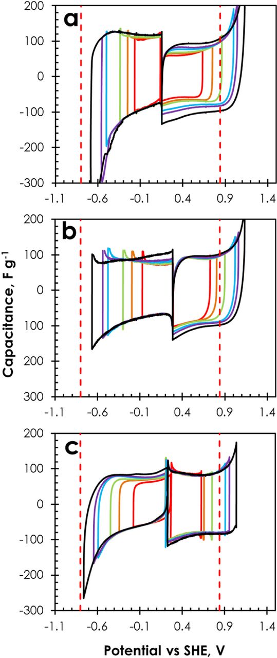
Figure 7. CVs (5 mV s−1) of individual electrodes of AC/AC supercapacitors in 1 mol L−1 Li2SO4 with (a) nickel (−)/nickel (+), (b) stainless steel (−)/stainless steel (+) and (c) nickel (−)/stainless steel (+) collectors, recorded up to cell potentials of 0.8 V, 1.0 V, 1.2 V, 1.5 V, 1.6 V and 1.8 V.
An increase of the anodic current from 1.0 V vs SHE (Fig. 7a) evidences the oxidation of Ni0 to Ni2+ or Ni(OH)2,47 and consequently a pale green residue appears on the edges of the positive electrode. Then, in analogy to rechargeable batteries, NiII (pale green Ni(OH)2) may be oxidized to NiIII (black NiOOH).48,49 Since NiOOH is a good mixed-conductor, with a high mobility of ionic and electronic species, its presence does not much impede the electrochemical performance of capacitors utilizing nickel collectors.
Considering now the vertical line representative of O2 evolution in Fig. 7b, it can be seen for the stainless steel (−)/stainless steel (+) system that oxygen evolution may occur at the positive electrode at a cell potential of 1.2 V. However, for this cell, an anodic current leap indicating the electrolyte decomposition, with possible oxidation of the carbon electrode and/or corrosion of the positive current collector starts to be remarkable from a cell potential of 1.5 V. This value is in agreement with our previous studies showing that AC/AC supercapacitors using aqueous Li2SO4 with stainless steel current collectors can operate safely up to 1.5 V.10
Finally, in case of the nickel (−)/stainless steel (+) system operating up to a cell potential of 1.6 V, the anodic current leap attributed to electrolyte decomposition, electrode oxidation and/or formation of corrosion products on the positive current collector is negligible (Fig. 7c). The accumulation of NiII and NiIII derivatives may be responsible for polarizing the surface of electrodes, causing a shift in rest potential (E0) from 0.285 V to 0.224 V vs SHE.50 The potential shift to lower values easily explains the absence of corrosion of the positive stainless steel collector for the cell combining nickel (−) and stainless steel (+). Hence, the application of nickel collectors helps to improve the long time operation of AC/AC supercapacitors based on 1 mol L−1 Li2SO4 electrolyte when high cell potentials are applied.
Enhancement of specific capacitance by surface modification of activated carbons
The surface of the activated carbon DLC Supra 30 was chemically modified with phenanthrenequinone moieties by grafting of electroactive 2-amino-9,10-phenanthrenequinone molecules using the reduction of the corresponding cation (see Carbon modification by grafting section), giving the DLC Supra 30-PQ carbon. The mass loading of PQ molecules in the DLC Supra 30-PQ carbon was estimated from TG analysis and cyclic voltammetry20 and is about 20 wt%. At least three measurements were performed on each batch using both techniques (TGA and CV), and the mass loadings were always in the same order of magnitude with an uncertainty of approximately 5% of the mass loading value. Fig. 8 shows the mass loss by thermogravimetric analysis (TGA), together with the CO2 and CO profiles obtained by thermoprogrammed desorption (TPD) for DLC Supra 30 and DLC Supra 30-PQ. The larger mass loss for DLC Supra 30-PQ, mainly related to CO2 and CO evolution, indicates an important surface functionalization, which is the proof of quinone grafting. The amount of CO-evolving groups increases from 453 μmol g−1 for DLC Supra 30 to 996 μmol g−1 for DLC Supra 30-PQ. The CO TPD pattern includes contributions from phenols or less stable carbonyl/quinones groups at 675°C.51 As it is observed on Fig. 8b, the amount of CO2-evolving groups also increases from 192 μmol g−1 for DLC Supra 30 to 1176 μmol g−1 for DLC Supra 30-PQ, with desorption peaks at 225°C, 475°C and 675°C assigned to strongly acidic carboxylic groups, less acidic carboxylic groups or carboxylic anhydrides and lactones, respectively.52 The relatively high value of evolving CO2 might be related to the presence of free radicals in the reaction medium, causing the formation of surface groups on activated carbon.
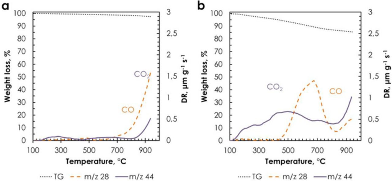
Figure 8. Thermogravimetric analysis and thermoprogrammed desorption on (a) DLC Supra 30 and (b) DLC Supra 30-PQ.
Fig. 9a shows the nitrogen adsorption isotherms at −196°C for as-received DLC Supra 30 and DLC Supra 30-PQ. Both isotherms display a rounded knee characterizing a wide range of micropore sizes; this is confirmed by the pore size distribution (PSD, Fig. 9b) curves which reveal pores up to ca. 3 nm. After grafting PQ, the BET specific surface area is reduced from 2066 to 649 m2 g−1, the micropore volume from 0.908 to 0.282 cm3 g−1 and the mesopore volume from 0.172 to 0.04 cm3 g−1. The interesting feature coming from the PSD comparison of both carbons is a comparable reduction of all pore sizes after grafting of phenanthrenequinone; this is traduced by very comparable values of average micropores size L0, e.g., 1.16 nm and 1.21 nm for unmodified and grafted carbon, respectively.
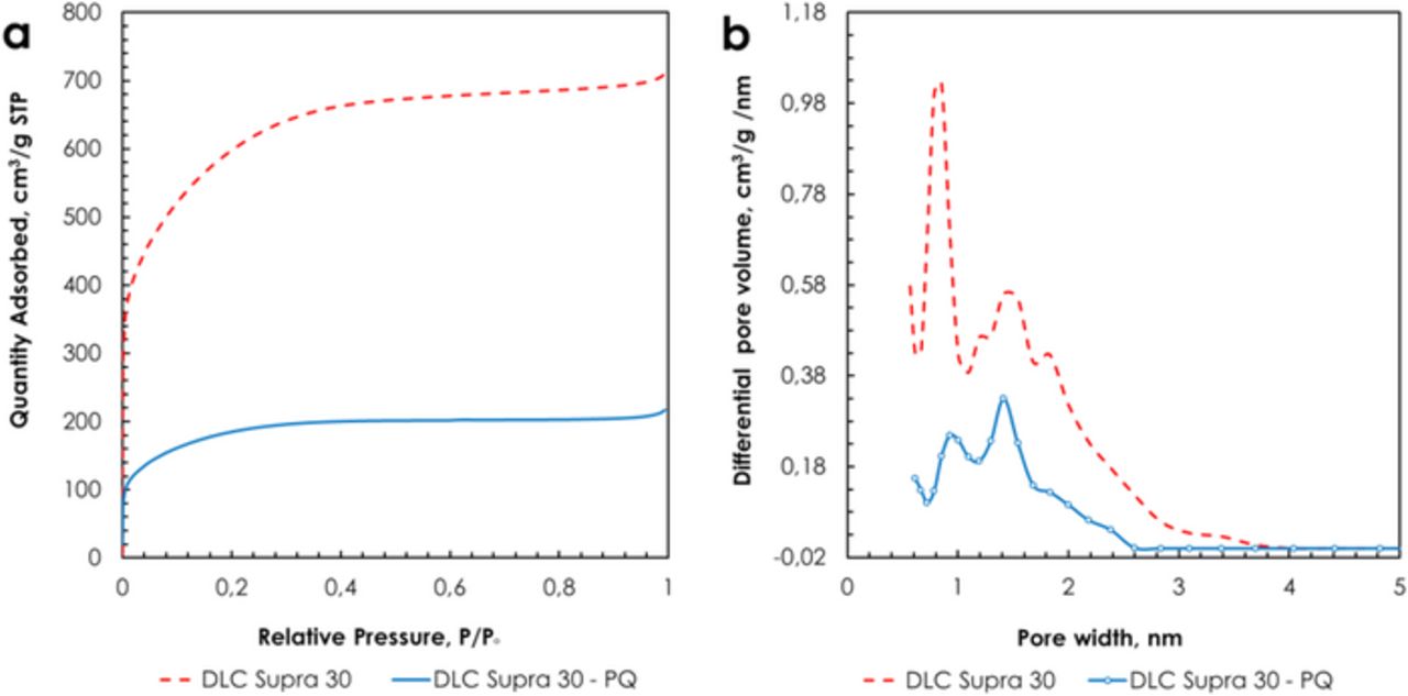
Figure 9. Nitrogen adsorption isotherms at −196°C (a) and pore size distribution (b) of DLC Supra 30 and DLC Supra 30-PQ.
Whereas literature reports data on electrochemical investigations of quinone-modified activated carbons in acidic and basic aqueous medium,34,35,53 to the best of our knowledge, data were not reported in media with pH close to neutrality for activated carbon grafted with phenanthrenequinone. Our preliminary studies using a three-electrode cell with DLC Supra 30-PQ as working electrode in 1 mol L−1 Li2SO4 have demonstrated a shift of PQ redox potential during the measurements. Since protons are part of the overall redox process, the redox potential is pH dependent, which is particularly pronounced for high porosity carbon powders in aqueous electrolyte. Since the nature of electrolyte and whether the solution is buffered or unbuffered have been found to have a major influence on the electrochemical performance of activated carbon electrodes modified by quinone derivatives,22 we have decided to use buffered solutions as electrolyte in order to eliminate any shift of redox potential during the electrochemical investigations on DLC Supra 30-PQ.
Fig. 10 depicts the cyclic voltammograms of DLC Supra 30 and DLC Supra 30-PQ in biphthalate buffer (pH = 4). The CV of as-received DLC Supra 30 displays a rectangular shaped voltammogram typical of the electrical double-layer (EDL) charging, whereas for DLC Supra 30-PQ, a pseudo-capacitive contribution related to the PQ molecules strongly bonded to the surface of activated carbon takes place together with the EDL formation.35 As a result of grafting PQ molecules, the specific capacitance increases from 82 F g−1 for DLC Supra 30 up to 194 F g−1 for DLC Supra 30-PQ. It is also interesting to note on Fig. 10 that the EDL capacitance of DLC Supra 30-PQ is comparable to that of DLC Supra 30, although the BET specific surface area of the former is 70% lower after grafting. The lowering of SBET can be explained by the fact that grafting occurs primarily at the entrance of micropores, hindering the access of nitrogen molecules probes to these pores during the gas adsorption measurements.20 However, one has to consider that ions and water molecules in the electrolyte might behave differently from nitrogen. This is in particular revealed by static contact angle measurements on pellet electrodes made from DLC Supra 30 and DLC Supra 30-PQ and showing values of 138.6° and 126.2°, respectively. Hence, due to the polarity of the strongly bonded molecules on the surface of the DLC Supra 30-PQ carbon (and probably also some other surface groups as revealed by the presence of CO2-evolving groups in TPD), the adhesion energy at the interface between the grafted carbon electrode and the electrolyte could be much larger in comparison to that of unmodified carbon in the same electrolytic medium.54 Despite the remarkably lower BET specific surface area of DLC Supra 30-PQ as compared to DLC Supra 30, better wettability of the grafted carbon allows better accessibility of the electrolyte to the pores (even if micropore entrance is slightly closed by quinone molecules), explaining EDL capacitance values in the same order as for the as-received carbon.
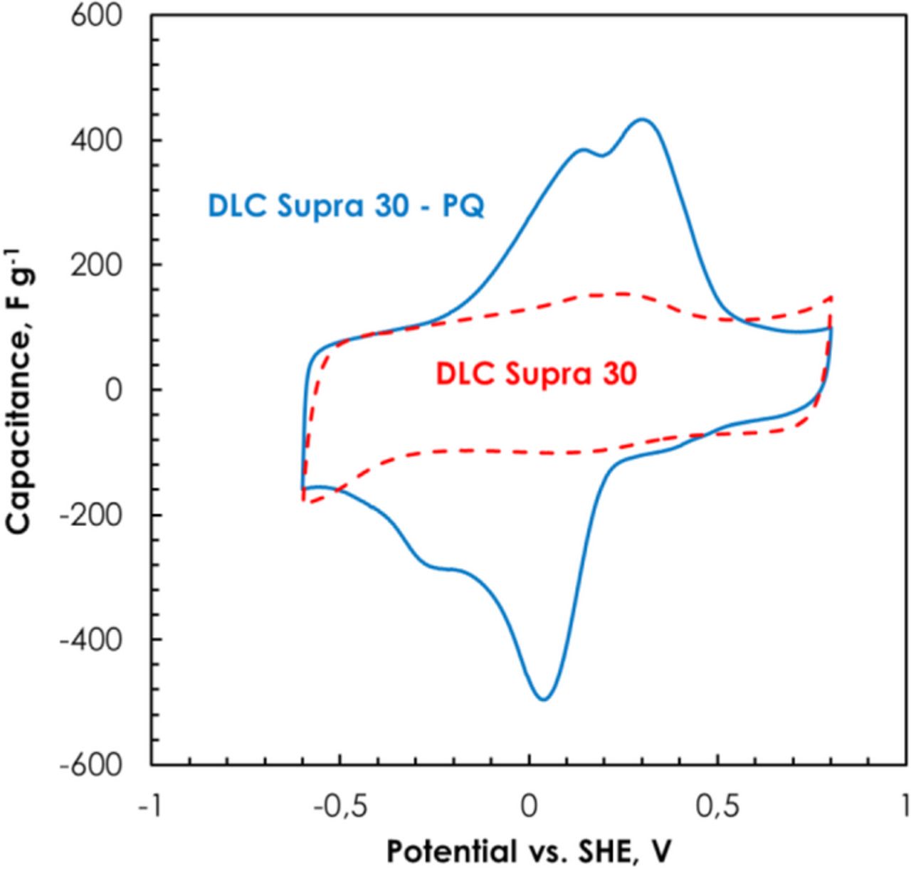
Figure 10. Cyclic voltammograms (2 mV s−1) of DLC Supra 30 and DLC Supra 30-PQ in biphthalate buffer.
The effect of electrolyte pH on the three-electrode cell properties of DLC Supra 30-PQ has been compared in 0.1 mol L−1 phosphate (pH = 7.2) and biphthalate (pH = 4.0) buffer solutions (Fig. 11). As expected from literature on grafted graphite powder electrodes,55 the anodic and cathodic peaks shifted toward negative potentials by increasing the solution pH; the specific capacitance values were 194 F g−1 to 228 F g−1 in biphthalate buffer and 0.1 M phosphate buffer, respectively. Two redox peaks are observed both in biphthalate buffer and phosphate buffer. Additionally, the reversibility of the redox reaction is smaller in phosphate buffer as compared to the biphthalate one. The peak-to-peak separation between anodic and cathodic peaks (ΔEp) evaluated from the CVs increases with the electrolyte pH, indicating that the overall process is kinetically much slower in the presence of phosphate buffer.32 At higher pH (phosphate buffer), the peaks current ratio (Ia/Ic) for peaks located at ca. 0.3 and 0 V was found to be greater than unity, which indicates possible kinetic disturbance in the electrode process56 contrary to biphthalate buffer.
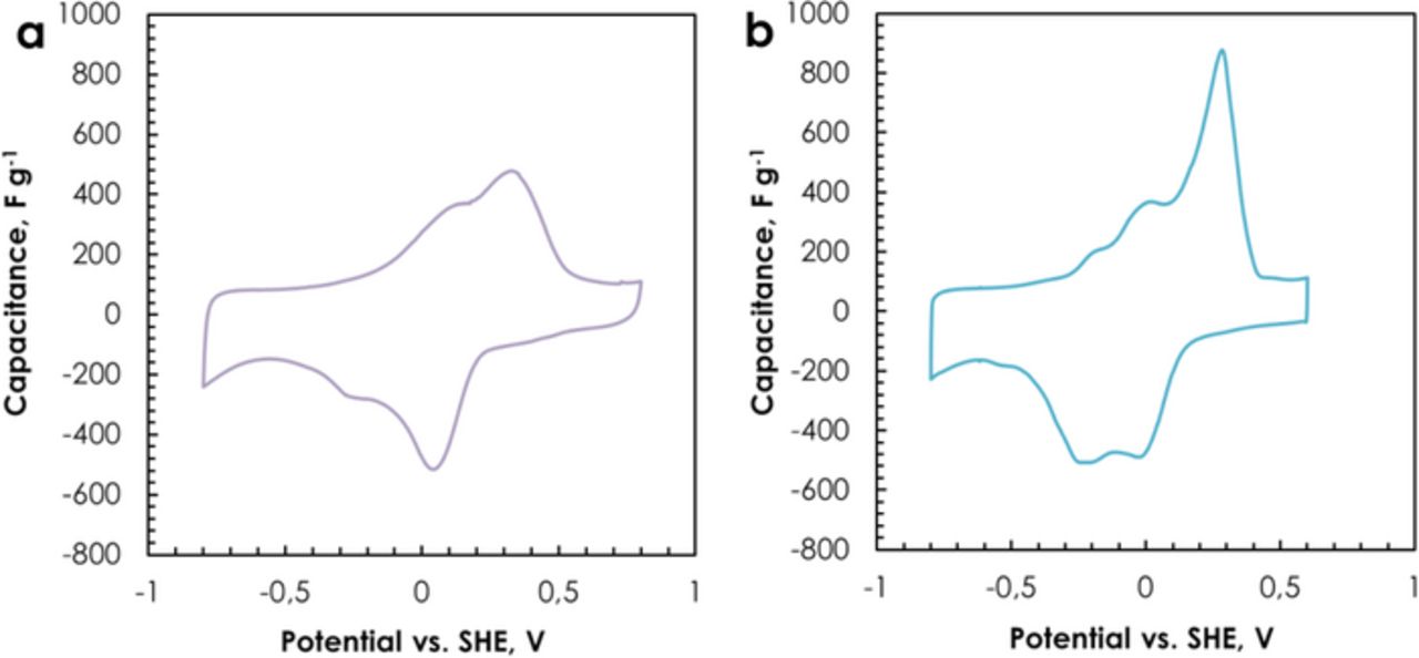
Figure 11. Cyclic voltammograms (2 mV s−1) of DLC Supra 30-PQ in (a) biphthalate buffer (pH = 4.0), (b) 0.1 M phosphate buffer (pH = 7.2).
At pH of about 4–10, quinone derivatives undergo a two-electron/two-proton reduction process.57 When the protons concentration in the electrolyte is close to the quinone equivalent concentration on the carbon surface, CVs show two waves.32 The wave at more positive potentials is universally interpreted as being due to the 2e−, 2H+ reaction, while the interpretation of the wave at more negative potential varies. Some authors suggest that it is related with the protons coming from either water or quinones. More recently, Shim and Park58,59 have argued that it is due to 1e− reduction to form the quinone radical anion. Wang and co-workers60 disputed this interpretation suggesting, instead, that it is due to 2e− reduction to form the quinone dianion. Besides, the two peaks in the cyclic voltammogram for both electrolytes could be associated to different types of bonding or different sites of grafting23 between the phenanthrenequinone molecules and the carbon surface. For example, it has been reported that in case of chemical modification without reducing agent, the derivatization might be occurring through a cationic intermediate. It reacts with surface carbonyl groups of the carbon powder and results in the formation of ester linkages.61
Conclusions
The pH of salt aqueous electrolytes is a key factor significantly affecting the performance of AC/AC capacitors based on these electrolytes. The generation of hydroxyl anions in the pores of the negative AC electrode drives the surface pH to values higher than 10 when almost neutral electrolytes such as 1 mol L−1 Li2SO4 (pH = 6.5 for the initial bulk solution) are used, resulting in a high over-potential for di-hydrogen evolution. Consequently, the AC/AC capacitors in these electrolytes are able to operate up to 1.6 V with high efficiency and low steady self-discharge profile. By contrast, in case of salt electrolytes with slightly acidic pH, as for example 1 mol L−1 BeSO4, the local pH in the AC porosity remains almost identical to the bulk electrolyte. As a consequence, the over-potential of di-hydrogen evolution is very low and it results in large di-hydrogen gas production and low efficiency.
Once considering that 1 mol L−1 Li2SO4 is an optimal salt for AC/AC capacitors in aqueous medium, improvements of the system were proposed to enhance its long term operation. Coated electrodes were manufactured in order to avoid the formation of decomposition products at the active material/current collector interface, and conductive carbon ink was used as sub-coating to improve the adhesion of the electrode material to the substrate. Nickel was introduced as an alternative for stainless steel foil in nickel (−)/nickel (+) and nickel (−)/steel (+) combinations. The nickel (−)/nickel (+) combination allows low and stable resistance values during 120 hours of floating at 1.6 V, although mixed-conductive nickel compounds are formed on the surface of current collectors. The most stable capacitance and resistance values (with no corrosion of the positive current collector) during floating at 1.6 V were revealed by the cell with nickel (−)/stainless steel (+) combination of collectors, owing to −105 mV shift of the operating electrode potentials attributed to the formation of electro-conductive nickel deposits.
Grafting of activated carbons with phenanthrenequinone molecules provides a new class of materials which display double-layer capacitance together with a redox response in buffer solutions of pH = 4.0 and 7.2. Despite the dramatic decrease in BET specific surface area of the PQ-grafted carbon, the double layer capacitance remains comparable to the pristine carbon, as a result of better wettability of the former. The redox contribution of grafted molecules combined with the double-layer capacitance of carbon provides a new class of materials which might be relevant for various applications in supercapacitors.
To summarize, using salt aqueous electrolytes with pH around 7 allowed carbon/carbon capacitors to exhibit large operating cell potential of 1.6 V, corrosion threat of the current collectors to be avoided by an appropriate selection of metals for each polarity, and finally capacitance values to be enhanced by grafting molecules with redox character on the AC surface. In future, the energy density of capacitors will be enhanced by implementing buffer solution and grafted carbon as negative electrode in asymmetric cell with a positive electrode made from e.g., manganese dioxide (MnO2).
Acknowledgments
The Foundation for Polish Science is acknowledged for supporting the ECOLCAP project realized within the WELCOME program, co-financed from the European Union Regional Development Fund. Norit is acknowledged for providing the DLC Supra 30 activated carbon, Kuraray for the YP 80F activated carbon, Timcal for the carbon black SUPER C65 and Arkema for the PVDF Kynar binder. French "Ministère des Affaires Etrangères" and Polish "Ministerstwo Nauki i Szkolnictwa Wyższego" are deeply acknowledged for supporting this project within the framework of Polonium # 31438NH.