Abstract
Capacity fading on cycling of lithium/sulfur batteries may result from at least four processes: increase of SEI thickness resistance, loss of cathode capacity (precipitation of sulfur species outside the cathode), agglomeration and thickening of sulfur species and increase in cell impedance as a result of reduction of the electrolyte. A very important issue that has not been properly addressed up to now is the influence of the type and content of the cathode binder on the cell parameters and on the electrochemical performance of lithium/sulfur batteries. We present here a detailed analysis and discussion of the electrochemical behavior, during prolonged cycling, of Li2S-based cathodes containing five different binders. The binders under investigation are: poly(vinylidene fluoride) (PVDF-HFP), polyvinylpyrrolidone (PVP), mix of PVP with polyethylene imine (PEI), polyaniline (PANI) and lithium polyacrylate (LiPAA). Sulfur utilization in the cathode follows the order of LiPAA > PVP:PEI > PVP > PVDF-HFP > PANI. Depending on the type of binder, cells provide 500 to 1400 mAh/g (S), 94.6–98.0% faradaic efficiency and enable more than 500 reversible cycles.
Export citation and abstract BibTeX RIS

This is an open access article distributed under the terms of the Creative Commons Attribution 4.0 License (CC BY, http://creativecommons.org/licenses/by/4.0/), which permits unrestricted reuse of the work in any medium, provided the original work is properly cited.
The lithium/sulfur battery has many attractive properties and is a promising candidate for many applications.1–5 In addition to high theoretical energy density (about 2600 Wh/kg), it is made of relatively inexpensive and non-poisonous materials. However, it has several disadvantages, which include self-discharge, short cycle life and too-low coulombic efficiency. These are caused by the low conductivity of sulfur and its final discharge products, expansion of the cathode upon lithiation and the solubility of sulfur and of lithium polysulfides in battery electrolytes. The expansion of the cathode occurs because the molar volumes of lithium sulfide and polysulfides are about 80% greater than that of sulfur. Partial dissolution of polysulfides leads to anode corrosion and to the formation of shorter polysulfide compounds. Short polysulfides, in turn, diffuse and migrate to the cathode where they re-oxidize or react with the solid sulfur at the cathode to form longer polysulfides, initiating a shuttle mechanism, which leads to low energy-conversion efficiency.
Early Li/S batteries contained cathodes made from a mix of bulk carbon and sulfur in a macrocomposite structure. Results showed poor capacity retention, low coulombic efficiency and severe capacity fading. Nole Rauh and Peled6–8 were the first - more than 30 years ago - to introduce the idea of loading sulfur into the porous structure of carbon materials. The primary Li/S battery exhibited 730 and 950 Wh/kg at room temperature and at 60°C, respectively9 and volumetric energy of 900 Wh/l and 1200 Wh/l at room temperature and at 60°C, respectively. The specific and volumetric energies were calculated on the basis of all components of the cell aside from the case. Sulfur utilization was 95% and the shelf-life, as estimated from anode-corrosion and aging tests, was 10 years. To the best of our knowledge, these specific-energy values are among the highest reported for primary batteries. The first rechargeable Li/S battery containing porous-carbon-loaded sulfur was published in 1989.8 A spirally wound 2/3A-size cell consisted of a 0.35 mm-thick Teflon-bonded porous carbon cathode that was loaded with solid sulfur. Such cells provided better electronic contact, improved energy density and up to 50 cycles.
In the years that followed, the focus shifted toward lithium-ion batteries and little progress was made in the fabrication of sulfur cathodes. In recent years, Nazar et al10 have been successful in improving the performance of Li-S batteries. They presented a feasible approach with the use of a mesoporous carbon framework of carbon tubes creating channels filled with sulfur melt. Since then, the Li-S system has regained the interest of the scientific community. To solve the problem of cathode expansion, an initial cathode structure, which contains the final discharge product - lithium sulfide (i.e. the cells are assembled in the discharged state) – has been tested by several researchers.11–16 So far, a very limited number of papers have been published on the assembling of a lithium/sulfur battery in the discharged state.17–19 Here too, there has been an effort to confine the Li2S in the carbon structures. Some showed improved results, one with initial capacity retention of close to 100% at a non-feasible rate of C/50 and 68% at a C/10 rate. Such coulombic efficiency and capacity fading are insufficient.12 Cairns et al20 proposed a cathode material with a core-shell nanostructure comprising Li2S nanospheres with an embedded graphene oxide (GO) sheet as a core material and a conformal carbon layer as a shell. The carbon coating is obtained by a CVD coating process with the use of a laboratory-designed rotating furnace. The cells exhibited 600 mAh/g reversible capacity for 150 cycles at 2C-rate.
Capacity fading on cycling results from at least four processes: increase of SEI thickness and SEI resistance on the lithium anode, loss of cathode capacity (precipitation of sulfur species outside the cathode), agglomeration and thickening of core-shell sulfur species and increase in cell impedance as a result of reduction of the electrolyte. Ideally, the SEI is a pure solid electrolyte with t+ equal to unity. However, in practice its thickness slowly increases with time, even under OCV conditions. The rate-determining step for this process is the conduction or diffusion of electrons through the SEI.21,22 Under OCV conditions, both growth mechanisms lead to a parabolic law of growth.21,22 On cycling, during the charge/discharge processes, SEI growth is even more complex as a result of retreat and plating of lithium underneath the SEI, between it and the lithium metal. This involves continuous breaking and repair of the SEI which leads to the formation of a spongy lithium deposit. Thus it is expected that after charge (plating of lithium), the apparent thickness of the SEI will be small and after discharge (dissolution of lithium), it will be greater.
In the lithium/sulfur battery, the shuttle mechanism of polysulfides and its repercussions can be described as follows. The soluble polysulfides always diffuse from the cathode to the anode. However on charge, they migrate from the anode to the cathode and on discharge they migrate in the reverse direction. So on discharge, two transport processes (diffusion and migration) contribute to the transport of polysulfide anions to the lithium anode. This leads to an increase in the concentration of polysulfides near the anode (possibly reaching several molar). On the other hand, during charge, the polysulfide concentration near the anode decreases. The reactions of polysulfides with lithium are complex; short ones are expected to cause precipitation of Li2S and Li2S2 as lithium-corrosion products, while long polysulfides may partially dissolve Li2S and Li2S2 particles from the SEI. This process leads to the accumulation on the anode of corrosion products (including Li2S and Li2S2) and thus to the thickening of the primary and the secondary SEI. This shuttle mechanism of polysulfides results in reduction of the faradaic efficiency of the battery, in some cases to below 70%.1–5,23 Many efforts have been made to minimize the reactions of polysulfides with the anode and to minimize their transport from the cathode to the anode. To summarize, the methods of overcoming the challenges of the Li/S battery include: reducing the solubility of the polysulfides by adding toluene to THF,9 increasing the concentration of the supporting electrolyte,15 encapsulation of the sulfur species (S or Li2S) in several types of cages24–26 and using polysulfide barriers and modified separators.27–29 Modification of the electrolyte by the addition of nitrate, as proposed by Aurbach,30 and film formation on the anode by its reaction with (CH3)3SiCl,31 were found to minimize the reaction of polysulfides with the anode, thus leading to longer cycle life.
A very important issue, one that has not been properly addressed up to now, is the influence of the type and content of cathode binder on the electrochemical performance of lithium/sulfur batteries.
Gau Liu et al.32 studied the effects of some binders, including PFM (9,9-dioctylfluorene-co-fluorenone-co-methylbenzoic ester) PEDOT-PSS (poly(3,4-ethylenedioxythiophene) polystyrene sulfonate) and PVP (poly(vinylpyrrolidone)), on sulfur-based cathodes. Lacey et al.22 studied PVP, polyethylene oxide (PEO) and carboxymethyl cellulose styrene-butadiene rubber (CMC-SBR) as binders for sulfur-based cathodes. With Li2S as starting cathode material, except for the common PVDF binder, only PVP mixed with PEO has been studied.33
We report here a detailed analysis and discussion of the electrochemical behavior of Li2S-based cathodes containing five different binders during prolonged cycling of a sulfur battery. The binders under investigation are: poly(vinylidene fluoride) (PVDF-HFP), polyvinylpyrrolidone (PVP), polyaniline (PANI), mix of PVP and PEI (polyethylene imine) and lithium polyacrylate (LiPAA).
Experimental
Materials
Commercial AR Li2S powder (Aldrich), MWCNTs (SkySpring) and Timrex 300 (SpecialChem), were used as starting materials for active-powder preparation. PVDF-HFP 2801 (Kynar), PANI (emeraldine base, Mw = 50000, Aldrich), PVP (Mw = 36000, Fluka), binders, Li2S, MWCNT, Timrex 300 and XC72 carbon were vacuum dried at 100°C overnight prior to use. PEO (Mw = 5000000, Aldrich) was dried at 60°C. LiPAA was froze and dried under vacuum in Leofilizer (Heto DRYWINNER). While in the text we write PVDF abbreviation, actually PVDF-HFP binder was used in all the tests.
Electrode preparation
The active material for the cathode was produced by wet ball milling of 50% Li2S, 40% Timrex 300 and 10% MWCNT in heptane for four hours at 450 rpm. This preparation procedure of the cathodes was the same for all binders used. The active powder was dispersed in a solution of the binder in N-methyl-2-pyrrolidone (NMP) (anhydrous 99.5%) except for LiPAA which was dispersed in THF. The cathode-powder dispersion was left overnight under magnetic stirring and cast on 15 μm carbon-coated Al foil. The cathodes were left overnight in an Ar-atmosphere glove box (MBraun) and then dried under vacuum at 120°C for four hours. The weight ratio of active powder to binder was 90:10 for PVDF and PVP, 93:7 for PANI and LiPAA and 94:6 for PVP: PEI (5:1) binders.
Battery assembly and performance evaluation
Coin cells (CR2032) were assembled in an Ar-atmosphere glove box (MBraun). The cathode was supported on a carbon-coated aluminum foil, two layers of Celgard 2400 separator (Celgard, USA) and Li foil (Rockwood Lithium). The electrolyte was 2 M bis(trifluoromethanesulfonyl)imide (LiTFSI) in dimethoxyethane (DME):1,3-dioxalane (DIOX)(1:1, v:v) with 0.15 M LiNO3 as an additive. The cells were equilibrated for 12 hours before testing was begun. Typically, the mass loading of the electrode was ∼1 mg.cm−2. Cells were charged and discharged over a voltage range of 1.8–3.6 V for the first cycle and between 2.8 V and 1.8 V for the remaining cycles. The cells were tested at C/10 for the first cycle, C/15 for the following ∼20 cycles, and C/10 thereafter as a durability test. The value of the 1 C rate for Li2S is defined here as 1166 mA.g−1. For these cycling tests, an Arbin SB2000 battery-testing station (Arbin Instruments, USA), BioLogic VMP3 system or MACCOR series 2000 system was used.
EIS of the batteries was carried out with the use of either Biologic VMP3 system or Solartron over the range of 0.01 Hz to 1 MHz. The data were analyzed with the use of EC-Lab software. The following parameters were determined: SEI resistance (RSEI), cathode charge-transfer-reaction resistance (Rct), Warburg parameter (W) and bulk resistance (Rb). Not in all cases we were able to determine all these parameters and we present here only those that are in good agreement with the equivalent circuit.
Results and Discussion
Cycling performance of cathodes with different binders
Beginning with Li2S as the cathode-active material has two major benefits: it can be coupled to a safer anode such as silicon, tin or graphite (instead of metallic lithium), and building the cell in the most expanded state helps to overcome the sulfur cathode distortion when it expands from sulfur to Li2S. PVDF is known as the common binder with no functional groups or any kind of ionic or electronic conductivity. PVP has amide carbonyl functional groups that can bind relatively strongly both to Li2S and polysulfides, thus reducing the loss of active material as a dissolved polysulfide.13,24,27,34 It is also believed to act as a redox mediator. PANI also has a nitrogen atom that may act as a polysulfide anchor and might even interact electrochemically with polysulfides by opening amine bonds in the presence of LiNO3.30 LiPAA is known as a good lithium-ion conductor, it has a reservoir of lithium ions that can compensate for Li+ loss during cycling of full cells and, in addition, it offers good binding capability.35 The formulas of all the binders are shown in Figure 1a.

Figure 1. (a) Formulas of the binders: PANI, PVDF, LiPAA, PVP, and PEI. (b) Cycling of cathodes with different binders at C/10. Inset PANI-based and PVP:PEI-based cathodes at prolonged cycling.
Figure 1b presents the cycleability of Li2S cathodes with different binders. It appears that the cathode binders affect both the sulfur utilization (the initial capacity - Qin) and the rate of capacity fading. The highest initial capacity (1200 mAh/gS) was found for LiPAA and the lowest (600 mAh/gS) - for PANI. Qin follows the order (Figure 1b and Table I) LiPAA > PVP:PEI > PVP > PVDF > PANI. We suggest that the more open and porous morphology of the cathodes, followed by better wettability (see Figure 7) and ion-conducting capability of LiPAA and PEI binders may explain the difference in Qin. Cells employing LiPAA and PANI cathode binders run for about 500 cycles, (see inset); (other cells were not considered because of the limitation of the number of available channels in our equipment). Figure 2 depicts charge- and discharge voltage profiles of all the cells with different binders. The profiles of the first cycle differ from those of the following cycles. The end voltage of the first charge is 3.6 V and for the rest, it is 2.8 V. Charging the cells to a voltage lower than 3.6 V for the first cycle, provides lower sulfur utilization. The charge/discharge mechanism of the lithium/sulfur battery is very complex. It depends on many parameters, including type of binder, type of electrolyte, type and content of carbon, temperature and current density. Many reports have been recently published, which lead to a better understanding of these processes.2,10,25 To simplify, the higher sloping plateau, from 2.5 to about 2.1 V, associated with the reduction of sulfur to Li2S4, we denote as QH; the second plateau at about 2.1 V, and down to 1.8 V, is associated with the reduction of Li2S4 to Li2S, is denoted as QL. However, the situation is much more complex and the reactions are not complete either on charge or on discharge. Polysulfides of different stoichiometry are involved in the charge/discharge process.2,10,25 We have found that the type of binder affects both QH, QL (Table II) and their sum, denoted as QT. For three binders, PVP:PEI, PVP and LiPAA, QH is about 30% of QT. However, in the case of PVDF, it is about 40%, and for PANI, QH is half of QT. In addition, PANI cells have the lowest current efficiency in the first cycle (Figure 2). This may result from precipitation of sulfur species outside the cathode, and so they are not available for the following discharge step. It is interesting to note that for all binders, the QH/QT ratio does not change from cycle 10 to cycle 200, despite the fact that the cell capacity drops by more than 30% (Table II). The constant QH/QT ratio indicates that the capacity-fading mechanism is the same for both QL and QH. In the case of PANI, the second (lower) voltage plateau is similar to that of all other binders. However, the reduction from Li2S4 to Li2S is less effective (a small QL value). The current efficiency of all cells is quite high, between 94.6% (PANI) to 98% (PVP) and the energy efficiency (Table I) varies between 87% (PANI) to 90.2% (LiPAA), close to that of lithium-ion batteries. It is well established that the soluble polysulfides act as a current "thief". Long polysulfides move from the cathode to the anode, are reduced to shorter polysulfides by the anode and move back to the cathode where they are reoxidized to long polysulfides. In addition, during cycling, a thicker SEI may be formed by precipitation of Li2S and LiNO3 discharge products on the surface of the anode, leading to higher cell impedance and thus to capacity fading. The rate of capacity fading per cycle (Table I) is lowest for PANI (0.14%) and PVP:PEI (0.15%) and highest for LiPAA (0.26%). In general, capacity fading is inversely proportional to the initial capacity. For all binders, the capacity fading per cycle for the first 20 cycles (Figure 3a), is up to one order of magnitude greater than that for cycles 21 to 200. It is lowest (0.88%) for PVP:PEI and highest for PVDF (1.47%). The capacity fading per cycle for cycles 21 to 200, is between 0.08% (PANI) and up to 0.19% for LiPAA. It seems likely that for the first 20 cycles, the concentration of polysulfides is higher (higher total capacity) and Qloss per cycle results from precipitation of insoluble sulfur species outside the cathode, reducing the availability of sulfur species for cell reactions. Figures 3a and 3b show the trend in the dependence of Qloss on the current efficiency, for all binders. For the first twenty cycles, Qloss is lower for cells with high current efficiency. For most binders, except for the mix of PVP: PEI, the current efficiency increases on prolonged cycling. The more pronounced is the increase of faradaic efficiency, the higher is the capacity retention for cycles 21–200.
Table I. Effect of binders on: Qloss, Q1disc, Current Efficiency and Energy Efficiency.
| Binder | Qloss (%/cycle) | Q1disc. (mAh/gS) | Current Efficiency (%) | Energy Efficiency (%) |
|---|---|---|---|---|
| PANI | 0.14 | 623 | 94.7 | 87 |
| PVP 5: PEI 1 | 0.15 | 960 | 96.7 | 89.5 |
| PVDF | 0.2 | 778 | 96.3 | 89.4 |
| PVP | 0.25 | 889 | 98.0 | 89.2 |
| LiPAA | 0.26 | 1184 | 97.3 | 90.2 |
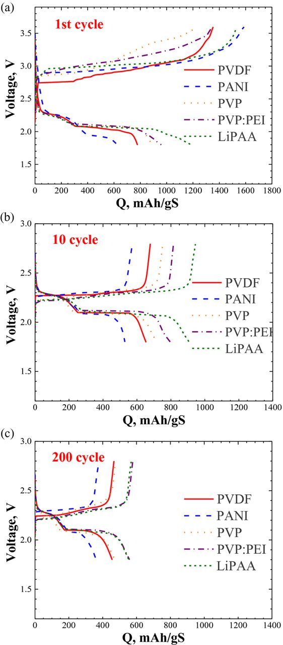
Figure 2. (a-c) Voltage profiles of the 1st, 10th and 200th cycles of Li/Li2S cells with LiPAA, PVP:PEI, PVP, PANI and PVDF based cathodes.

Figure 7. SEM images of Li2S cathodes with PVDF and LiPAA-based cathode.
Table II. Effect of cycling and binders on QT, QL and QH.
| Cycle10 | Cycle 200 | ||||||
|---|---|---|---|---|---|---|---|
| Binder | Qloss (%) | QT (mAh/gS) | QH/QT (%) | QL/QT (%) | QT (mAh/gS) | QH/QT (%) | QL/QT (%) |
| PANI | 0.14 | 529 | 50 | 50 | 361 | 54 | 46 |
| PVP:PEI | 0.15 | 796 | 31 | 69 | 558 | 32 | 68 |
| PVDF | 0.2 | 653 | 39 | 61 | 455 | 38 | 62 |
| PVP | 0.25 | 717 | 32 | 68 | 473 | 33 | 67 |
| LiPAA | 0.26 | 907 | 31 | 69 | 554 | 31 | 69 |

Figure 3. Qloss and current efficiency correlation.
The rate capability of lithium/sulfur cells was studied for two binders - PVDF and LiPAA (Fig. 4). Cells were run at 0.07 C and up to 2 C. Cells containing a cathode with LiPAA binder, perform better than those with the PVDF-binder cathodes. At 1 C, the capacity of both cells dropped by about 50%, while at 2 C, the capacity of the LiPAA cell decreased by 80% and that of the PVDF cell dropped close to zero. We attribute the higher rate capability of the LiPAA cell to better morphology of the cathodes, lower charge/discharge overpotential relative to the PVDF cell (Figure 2) and the highest energy-conversion efficiency (Table I).
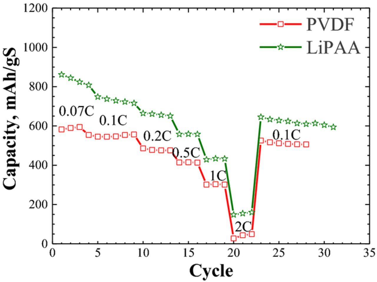
Figure 4. Rate capability of Li2S/Li cells with PVDF and LiPAA based cathodes (the tests started on cycle 20).
dQ/dV curves
The voltage plateaus of the charge/discharge profiles appear as well pronounced peaks in normalized dQ/dV curves. The integrals of the peaks are associated with the relative capacities of the different steps in the charge/discharge reactions. The discharge peaks seen in dQ/dV plots of PANI and PVDF cells (Fig. 5a) at 2.27 V, associated with the S-to-Li2S4 reaction, are broad and reflect slow kinetics. The narrow peaks at 2.08 and 2.09 V show fast kinetics of electrochemical conversion of Li2S4 to Li2S. The two dQ/dV peaks on charge are much closer to each other, than are the corresponding peaks on discharge. This results in different charge/discharge overpotentials of the Li2S ↔ Li2S4 and Li2S4 ↔ S reactions. Hence, despite the slower kinetics, the charge/discharge Li2S4 ↔ S overpotential is only 20 mV, while that of Li2S ↔ Li2S4 is about 100 mV. When comparing the dQ/dV curves of PVDF and PEI-PVP cathodes the similarity of discharge profiles stands out, while the charge profiles diverge. In the dQ/dV charge curves of the PVP:PEI cell, three peaks of different intensity and area can be distinguished. It is interesting that the maximum of the broad intermediate charge peak of the PVP:PEI cathode almost coincides with the maximum of the first sharp charge peak at 2.28 V in the dQ/dV charge curve of the PVDF cathode. Here, even more clearly than in Figure 2b–2c, one can see that the PVP:PEI cathode (Figure 5b) shows lower charge/discharge overpotential (57 mV) of the first step of sulfur oxidation than do the PVDF and PANI cathodes. We can speculate, therefore, that in the PVP:PEI cathode the multistep oxidation of sulfur may occur via the formation of Li2S2 according to the scheme Li2S → Li2S2 → Li2S4 → S. On prolonged cycling, the position and intensity of the dQ/dV curves of the PVP:PEI cathodes do not change (Figure 5c), indicating high electrochemical stability of the cell. Similar behavior was observed for the LiPAA cathode. While on cycling, the shape of the dQ/dV charge plots of the PVDF cathode (Figure 5d) becomes similar to that of the PVP:PEI cathode, the charge/discharge overpotential of the sulfur-oxidation reaction remains higher.

Figure 5. Effect of binders on dQ/dV profiles.
Therefore, in spite of the same capacity fading for both discharge steps in PVP:PEI, PVDF and PANI cathodes, higher charge/discharge overpotential and/or different charge pathway deteriorates the performance of PVDF and PANI cells, particularly during initial cycling (up to 20–25 cycles). Swelling of PVDF and PANI in DME-DOL electrolyte followed by increased tortuosity in the cathode may, in turn, slow dissolution of long polysulfides and enable high capacity retention on prolonged cycling.
Electrochemical-Impedance Spectroscopy (EIS) analysis
Impedance tests of Li2S/Li cells containing cathodes with different binders have been carried out after prolonged cycling. Figure 6 displays the Nyquist plots of the cells after about 22–50 cycles. Cycling was carried out according to the procedure described in the Experimental section. The measurements were taken at a discharged state of the cathode under a potentiostatic mode of 20 mV amplitude and over the frequency range of 1 MHz – 0.01 Hz.
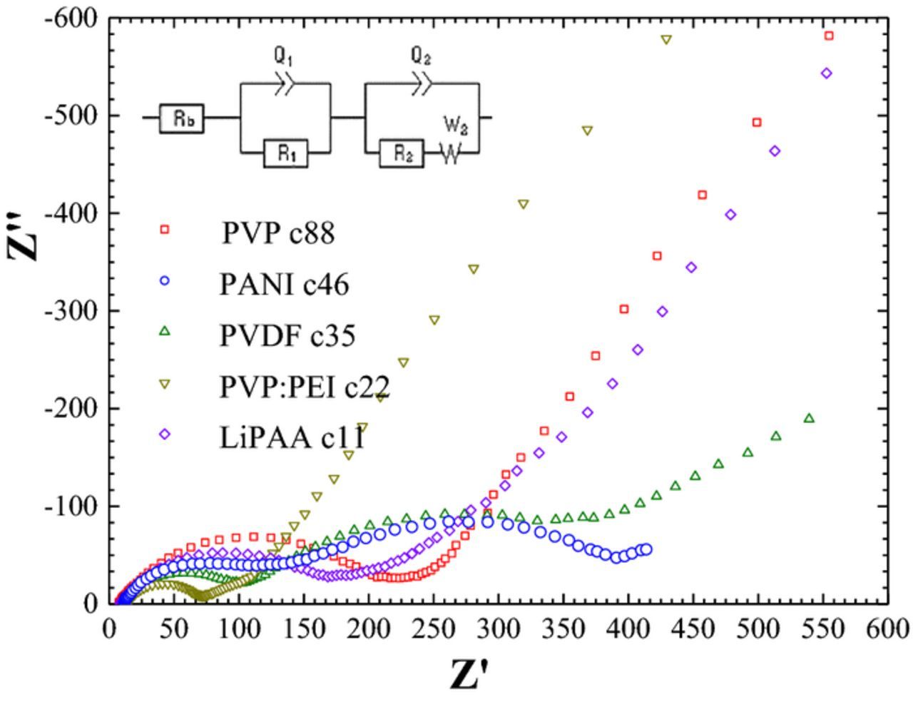
Figure 6. Nyquist plots of a Li2S/Li batteries comprising cathodes with different binders. Inset - equivalent circuit used for fitting.
The typical high-frequency semicircle is attributed to the impedance of the solid electrolyte interphase formed on the lithium anode with a capacitance of about 10 μF.cm−2. The second depressed semicircle at a lower frequency region with 1 mF.cm−2 capacitance is associated with the charge-transfer resistance complicated by the Warburg function. The latter may reflect diffusion of lithium ions to and from the electrode/electrolyte interface, in the secondary porous SEI layer and in the bulk of the cathode. The EIS spectra were fitted to the equivalent circuit given in the inset of Figure 6. The bulk electrolyte resistance is labeled as Rb, the SEI impedance as R1, Q1 and charge transfer in Li2S-based cathode as R2, Q2, the Warburg factor as W.36,37 The capacitive element (Q) symbolizes a capacitance with a constant phase element (CPE) that defines the grade of compression of the semicircle in the Nyquist plot. The CPE can be related to indefinite non-homogeneous morphology of the electrode surface.
As expected, the bulk electrolyte resistance of about 10 ohm.cm2 is not influenced by the binder type of the cathode. During initial cycles, the resistance of the SEI (RSEI) is about 70–80 ohm.cm2. The lowest charge-transfer resistance was found for the cells with LiPAA and PVP-PEI cathodes. It was found that RSEI almost does not change on cycling, while charge-transfer resistance and the Warburg factor in the cell with the PVDF-based cathode increase (Table III). This may indicate possible agglomeration of the particles in the cathode and increased tortuosity caused by swelling of PVDF by the electrolyte. This, in turn, is followed by a decrease in the rate of diffusion of the lithium cation, in agreement with Deng et al.38
Table III. EIS analysis parameters for cycled PVDF-based cathode.
| Cycles | Rb (ohm) | R1 (ohm) | R2 (ohm) | W2 (ohm·s−½) |
|---|---|---|---|---|
| 19 | 9.9 | 103.7 | 91.9 | 18.5 |
| 35 | 11.6 | 89.3 | 245.7 | 45.7 |
| 205 | 8.0 | 77.4 | 1228 | 181.3 |
SEM images of some cathodes before and after cycling are shown in Figure 7. To study the effect of binders on the morphology of the cathodes on prolonged cycling, the cells are disassembled both in fully charged and discharged states, and the cathodes are thoroughly washed and dried. The differences in morphology may be observed in the fresh cathodes as well as in cycled electrodes. In the SEM images of cycled cathodes, both in fully charged and discharged states, pores are blocked. The differences in morphology may indicate the different amounts of precipitated sulfur and sulfide species. After charge, the LiPAA cathode looks clear and porous compared to the other binders.
Summary
Five polymers with different surface-functional groups and their mix, namely PVDF-HFP, PVP, PANI, LiPAA and PVP-PEI, were tested as binders in Li2S-based cathodes of lithium/sulfur batteries. It was found that the cathode binders affect both the utilization of sulfur and the rate of capacity fading. The highest initial capacity (1200 mAh/gS) was found for LiPAA and the lowest (600 mAh/gS) - for PANI. For all binders, the capacity fading per cycle for the first 20 cycles is up to one order of magnitude greater than that for cycles 21 to 200; it is lowest (0.88%) for PVP:PEI and highest for PVDF-HFP (1.47%). The capacity fading per cycle for cycles 21 to 200 is between 0.08% (PANI) and 0.19% for LiPAA. Analysis of the dQ/dV curves provides grounds for suggesting different charge mechanisms in the cells with PVDF and PANI cathodes as compared to those with PEI:PVP and LiPAA cathodes. For the former the charge occurs as follows: Li2S→Li2S4 → S. For the latter, an additional low- overpotential step Li2S →Li2S2 facilitates high electrochemical stability of the cells.
The cells with LiPAA and mix of PEI:PVP delivered 550 mAh/gS reversible capacity after cycle 250 as compared to 438 mAh/gS of common PVDF-HFP binder. Depending on the type and content of binder, cells provide 500 to 1400 mAh/gS, 94.6–98% faradaic efficiency and enable more than 500 reversible cycles. We believe than the amino groups of PEI and the PAA oxygens interact with sulfide and polysulfide species to promote a higher stability of battery.
Acknowledgments
The research is supported by ISF and Horizon2020-HELIS project.