Abstract
Solid-state batteries employ composite electrodes which contain a solid ion conductor, a solid active material, a conductive additive, and a binder. The electrode microstructure fundamentally differs from electrodes in conventional batteries because the pore region is ion blocking. While there is extensive research on how to integrate a lithium metal with inorganic electrolytes, there is less knowledge on how an electrode can be integrated with an inorganic electrolyte. Solution processing techniques are ideal for scalable manufacturing and rely on creating an ink which combines the solid material, a binder, and solvent. Ink engineering relies on tailoring the fluidics (rheology), aggregation behavior, and stability for a desired coating process. In this work, we systematically probe the role of two ink constituents: the (1) binder, and (2) solvent on electrode microstructure formation. Lithium titanate anodes achieve nearly a 3-4X increase in capacity from 1.5 mAh/g and 3 mAh/g to 9 mAh/g and ≥12 mAh/g when a high viscosity solvent is employed. The binder plays a larger role in dictating performance of the electrode than surface adhesion properties. Inks with well dispersed constituents led to more effective electrodes for charge storage.
Export citation and abstract BibTeX RIS

This is an open access article distributed under the terms of the Creative Commons Attribution 4.0 License (CC BY, http://creativecommons.org/licenses/by/4.0/), which permits unrestricted reuse of the work in any medium, provided the original work is properly cited.
There is increasing interest in all-solid-state batteries (ASSBs) for portable electronic and electric vehicle applications.1 Solid-state batteries utilize a solid electrolyte to conduct ions rather than a flammable and volatile organic liquid electrolyte. Thus, solid-state batteries are potentially safer than traditional batteries and can achieve higher energy densities when paired with a high voltage cathode and/or low voltage metal anode.2,3 Several solid electrolytes exist and broadly fall into two material categories: (1) organic and (2) inorganic. Polymer electrolytes are advantageous because they can be manufactured easily into thin films, are mechanically robust, and flexible.4 However, polymer electrolytes have lower ionic conductivities than inorganic electrolytes.5 Among the most promising solid electrolytes are sulfide-based electrolytes (Li-Ge-P-S)6 (25 mS/cm) and Garnet-Type Li7La3Zr2O12 (LLZO) solid electrolytes (≥1 mS/cm). Sulfides, unlike Garnet ceramics, have a low grain boundary resistance and can be cold processed to high densities. However, Garnet-type oxides are more stable against lithium metal than sulfide electrolytes. There is a growing body of work which describes how to integrate an inorganic electrolyte with lithium metal and less work which describes how to engineer an electrode for a solid-state battery. Scalable manufacturing of all solid-state batteries requires a facile approach to whole cell processing and manufacturing.
Electrode processing in solid-state batteries is a nascent field with few reports discussing the role of composition on performance.7 All electrodes contain a solid active material, a binder, and a conductive additive.8 The active material participates in charge storage, the binder provides mechanical stability during electrochemical cycling, and the conductive additive aids in electron transport in the electrode. Traditional electrodes in electrochemical systems are porous in order to provide ion transport.8–12 In traditional electrode processing, electrodes are tape cast on metal (Al or Cu) foils, followed by drying. The pores are filled with a liquid electrolyte which provides continuous ionic transport pathways (Fig. 1a). The interfacial resistances between electrodes (solid) and electrolytes (liquid) are small as liquid electrolytes can infiltrate into porous solid electrodes.13 In solid-state batteries these electrodes are known as composite electrodes because the electrodes contain solid electrolyte (0–40%) apart from the active material (50–85%).14,15 Typically, the remaining solid content is a conductive additive (i.e. carbon black).15 Pore regions in composite electrodes are ion blocking and can increase the tortuosity of the electrode.16,17 Tortuosity in the electrodes will significantly affect the rate performance of the electrodes. Ideally the electrode should be completely dense, however mechanical strain on lithiation and delithiation can significantly deteriorate the electrode microstructure. Hence, porosity and pore size distributions of the composite electrode must be tailored to minimize tortuosity and enable safe mechanical expansion and contraction. In addition, delamination of the electrode can significantly decrease the lifetime of a device, and thus adhesion effects are also important to consider. The composite electrode microstructure, composition, and properties play a significant role in determining the rate capability, lifetime, and energy density of a solid-state battery (Fig. 1b). Thus, the ability to tailor these properties during manufacturing is paramount for the adoption of solid-state batteries.
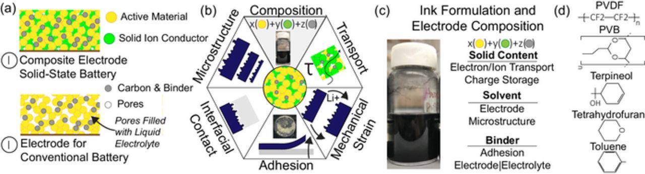
Figure 1. All solid-state batteries utilize a composite cathode which contains a solid ion conductor. In contrast, traditional liquid batteries electrolyte-filled porous regions for ion conduction to the active materials (a). The underlying properties (i.e. composition, microstructure, etc.) of the composite cathode play a significant role in the performance of a solid-state battery (b). A typical ink to fabricate composite electrode (c). Chemical structures of the solvent and binders used in this study (d).
Thin film deposition and solution processing techniques enable uniform coating of composite electrodes onto substrates. Typically, electrodes are coated directly onto a current collector or an inorganic electrolyte. The latter approach provides lower interfacial resistances between the solid electrolyte and electrode.18,19 Solution processing techniques rely on dispersing the electrode components in a solvent (i.e. ink) and employing various coating strategies to form the electrode (Fig. 1c).10 Deposition methods19,20 as well as co-sintering21,22 approaches have also been employed for composite electrode fabrication. Currently, electrode processing techniques mimic conventional battery (with liquid electrolyte) manufacturing processing. This approach does not address the fundamental microstructure differences that exist between conventional and solid-state battery electrodes. Capacity enhancement for solid-state batteries is primarily sought by a range of interfacial engineering strategies. These methods are effective, however are challenging to scale. Ink engineering offers a facile approach toward improving capacities of solid-state batteries.10,23–25
Electrode inks are examples of colloidal inks.10 All inks constitute of solvent, polymer and electrode materials. The solvent is primarily used for dispersion of materials to enable solution processing of electrodes. Binders are used both for enabling effective dispersion and providing mechanical strength to the structure in conventional electrodes. Composite electrode inks possess quaternary interactions between the active material, solid electrolyte, conductive carbon, binder and the solvent. Careful selection of the solvent and binder system can tailor the electrostatic and steric interactions within the ink and can prevent agglomeration of the active material as well as help improve the active material—electrolyte interface within the electrode.17 Ink composition and its effect on battery performance has been extensively studied for conventional lithium ion batteries.22,25–36 Comparatively less work has been carried out on ink engineering for composite electrodes.
The surface chemistry of the active material, the concentration and type of conductive additive, the polymer loading, and solvent play a role in forming the electrode microstructure. The most widely used binder in conventional battery (with liquid electrolyte) systems is polyvinylidene fluoride (PVDF). PVDF directly interacts with the active material via weak van der Waals forces.38 The weak nature of this interaction can lead to inefficient binding between the particles which impacts electrical conduction mechanisms. This weak interaction is compounded in composite electrodes where effective contact and binding is necessary for both electron and ion conduction mechanisms.16 In all ceramic systems, the binder serves to control the solid-solid interaction and is subsequently burned out.39–41 A good binder for ceramics has a slow burn rate to enable strength during pyrolysis while imparting sufficient binding strength. These properties have to be considered while designing inks based on the complete process cycle (mixing, casting, drying steps). Agglomeration of ceramics can decrease the density of the final material. Since composite electrodes are part ion conducting material (garnet oxide) and part lithium ion host (spinel oxide) it is unclear what type of binder is best suited for effective transport properties.
In this study, we employ principles of ink engineering to optimize the electrode processing parameters. Specifically, we seek to probe the role of two ink constituents (binder and solvent) on the electrode formation process and performance of ASSBs. Mixture of tetrahydrofuran (THF) and toluene is often used as a solvent19,42–44 and polyvinylidene fluoride (PVDF) is the most traditional choice for binder in battery industry. We study terpineol and polyvinyl butyral (PVB) as alternatives for solvent and binder respectively. These were selected as polyvinyl butyral (PVB) is an organic polymer which has both a slow burn rate and can act as a binder,45 while terpineol has a very different viscosity as well as disparate surface tension (Table I). We demonstrate that the selection of solvent and binder can dramatically change the battery performance with the configuration under study. Less agglomeration in electrode and better contact between cathode and LLZO electrolyte are achieved leading to a spatially uniform Li+ flux and a homogeneous distribution of local current density. Ink engineering is shown to significantly improve the capacity of the LTO/Li half-cell. Coupling ink engineering with interfacial modification routes is proposed to enable scalable production of high-performance ASSBs.
Table I. Physical properties of Tetrahydrofuran, Toluene, and Terpineol solvents.
| Density | Boiling | Viscosity | Surface | |
|---|---|---|---|---|
| Solvent | (g/ml) | Point (°C) | (mPa*s) | Tension (mN/m) |
| Tetrahydrofuran | 0.88 | 67 | 0.48 | 26.4 |
| Toluene | 0.87 | 111 | 0.59 | 28.52 |
| Terpineol | 0.93 | 215 | 97 | 33 |
Experimental
LLZO pellet preparation
A conventional solid-state-reaction method was employed to prepare Al-doped LLZO powder, using LiOH, La2O3, ZrO2, and Al2O3 as the starting materials. Briefly, 2.5 g LiOH (pre-dried at 200 C for 6 h), 6.6 g La2O3 (pre-dried at 900°C for 12 h), 3.3 g ZrO2, and 0.15 g Al2O3 were mixed and ball milled for 4 h at 500 rpm (Pulverisette 7 premium line, Fritsch). The mixture was then annealed at 800°C for 10 h after drying. The obtained powder was ball milled again for 4 h at 500 rpm and dried overnight under vacuum. Pellets (1 mm thick, 10 mm diameter) were prepared by uniaxial pressing with a pressure of 400 MPa. The green body pellets with density of 50% were covered with the same mother powder and sintered in alumina crucibles at 1065°C for 6 hours.
Electrochemical characterization
Electrode inks are composed of 10 wt% carbon black, 10 wt% binder (PVDF or PVB), 40 wt% Li4Ti5O12 (LTO) and 40 wt% LLZO powder. LTO was sourced from MTI Corporation and was used as received (D10 = 0.2–0.6 μm). The total solid content in the electrode ink was 30 wt%. All inks ball milled at 500 rpm for 30 min. THF/toluene (4:1 volume ratio) or terpineol was used as a solvent. LLZO pellets were dry polished to a thickness of ≈600 μm, sonicated in alcohol and dried under vacuum. Cathode slurries were cast on LLZO pellets and dried overnight at 80°C in an Ar-filled glove box. The gravimetric density of the active cathode material was controlled to be 2.5 mg cm−2. Li metal foil was molten on the other side of LLZO pellets on a hot plate with a temperature of 180°C in glove box. ASSBs with configuration of LTO/LLZO/Li were assembled in 2032 coin cells in glove box. The tests were conducted at 95°C. Cells were cycled between 2.5 V and 1.0 V with current densities of 5, 12.5, 25, 5 A kg−1 sequentially for charge-discharge tests. The currents for galvanostatic charging were calculated using the active material loading in the electrode. The capacities are normalized to the active material loading in the electrode.
Materials characterization
Stress test was conducted with a mechanical testing system (Instron 5944, Instron, USA). Ceramic substrates were fixed by super glue and testing rods were attached to electrodes by using super tape. The crystal phase was detected by powder X-ray diffraction (XRD, Rigaku Smartlab, Regaku, Japan) with a step of 0.01°. Surface tension of the cathode inks was measured using a bubble pressure tensiometer (Kruss BP50 tensiometer, KRUSS GmbH, Germany). Surface tensions were recorded for bubble ages from 15 ms to 2000 ms at approximately 23°C. The instrument was calibrated with a water reference prior to each measurement. Electrode inks were rheologically characterized using a DHR3 Hybrid Rheometer (TA instruments, USA) in a stress-controlled mode. Inks were pre-sheared at 100 s−1 for 2 minutes and allowed to rest for 10 minutes prior to any tests to remove any mechanical history in the samples. Average of at least three measurements are reported. Suspensions for particle size measurements were made by dilution of ball-milled inks to 0.3% solid loading. Malvern NanoZS Zetasizer instrument was used for dynamic light scattering studies. The physical properties of solvents used for the experiments are listed in Table I. Images of the anodes were taken on an optical microscope. X-ray photo electron spectroscopy methods analyses were performed using an Ulvac-PHI Versaprobe 5000. Different LLZO samples were submersed in each solvent for a period of 1 minute. Samples were vacuum dried and stored in a glove box for transfer to the XPS instrument. In order to minimize air exposure, samples were transferred in a sealed container. Samples were mounted onto a sample holder using BeCu clips. The mounted samples were pumped in the intro chamber until the pressure dropped below 1 × 10⁻⁶ torr. Monochromatic Al α X-rays (1486 eV), a 100 μm diameter X-ray spot rastered over a 600 μm by 400 μm area, and a takeoff angle of 45 degrees off sample normal were used in each acquisition. Pass energies of 187.7 eV and 23.5eV were used for the survey and high-resolution acquisitions, respectively. Charge neutralization was accomplished using 1.1 eV electrons and 10 eV Ar+ ions. CasaXPS processing software was used to analyze the resulting data. Binding energies were calibrated to -CH2- type bonding in the carbon 1s spectrum of 284.8 eV.
Results and Discussion
Electrochemical performance of the composite electrode
A lithium titanate composite electrode demonstrates drastically different performances depending on how the ink is formulated. Depending on the binder|solvent formulations, capacities between 1 and 15 mAh/g are observed at 5 A/kg charging rates (Fig. 2a). We observed that PVB gave both the best performance (Terpineol) and worst performance (THF/Toluene) depending on the ink's solvent. Both electrodes demonstrate an interesting behavior of starting with a very low capacity and increasing rapidly in the first 10 cycles. This 'break-in' period may be required to activate the polymer with either ionic carriers or to mechanically alter the polymer. Composite electrode inks formulated with Terpineol (independent of binder) perform better than inks formulated with a mixture of THF/Toluene (Fig. 2b).
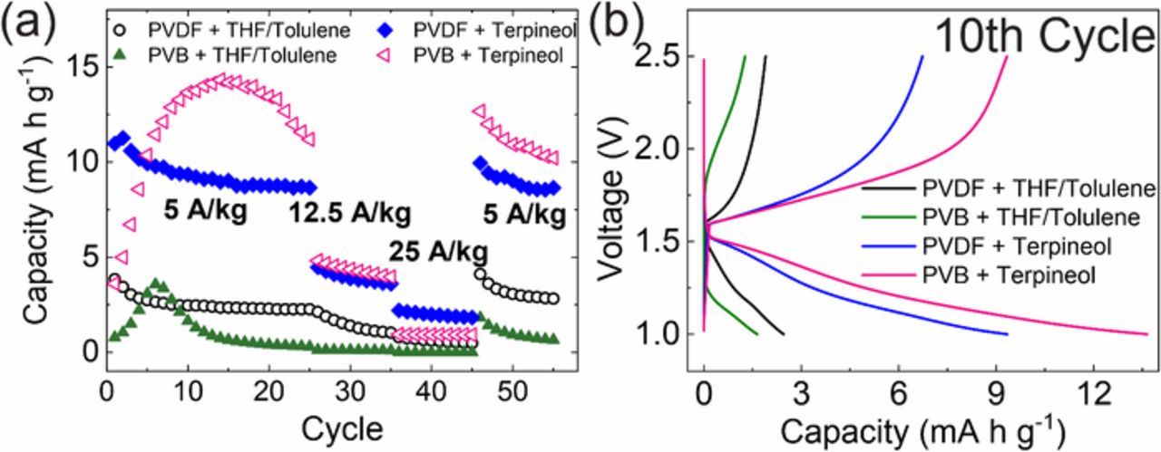
Figure 2. Anode was processed with: solvents of THF/toluene and terpineol, binders of PVDF and PVB. (a) Capacity retentions at 5, 12.5, 25, and 5 A/kg sequentially; (b) Characteristic charge/discharge curves for the 10th cycle at 95°C.
Characterization of composite electrode inks
Engineering inks requires precise control over how the ink flows (rheology/fluidics), how the active material orients and aggregates, and the ink stability.10 Polymer-solvent interactions can impact the structure the polymer takes in the electrode and how well an ink flows.46 Forming stable liquid-air interfaces during solution processing enable uniform coating and limits defects (i.e. coffee ring effect).47,48 Dynamic surface tension measurements describe how effective a liquid is at forming a stable interface with respect to a property known as surface age.47,49 During coating, the inks are subjected to a sudden increase in surface area.49 Component diffusion occurs within the ink as a result of surface free-energy minimization.50 Polymers typically align themselves at the free interfaces to accommodate hydrophilic-hydrophobic interactions within their structure and help in minimizing the surface tension.51 Dynamic surface tension for a good ink will decrease rapidly and maintain a constant surface tension with surface age (Fig. 3a). The surface tension of neat terpineol, tetrahydrofuran, and toluene are 33, 26, and 29 mN/m (Table I). One of the inks contains THF/Toluene in a 4:1 ratio, so we can extrapolate that the surface tension of the blended solvent (THF/Toluene) is lower than terpineol (Fig. 3a). All polymer solutions except PVB-terpineol system show surface tension behavior very close to that of the pure solvent system. This suggests that polymer solvation within these systems is favorable and the polymer-particle interactions within these systems would be minimal. The increase in surface tension at low surface ages for the PVB-terpineol system indicating that polymer-particle interactions will be higher for this system. Surface tension is also related to the vapor pressure of the system.52 Surface tension arises from cohesive forces acting on the molecules at the free interface with the atmosphere. Higher surface tension implies a stronger cohesive energy for the molecules within the surface layer leading to a reduced vapor pressure. When an electrode is cast, a liquid supernatant must form for solvent evaporation. During this step, the polymer diffuses to the free-boundary of the system to reduce the free energy. If the surface tension at this polymer rich 'skin' is low, polymer can be lost due to volatilization.32 It is hypothesized that PVDF (a linear-chain polymer) that can reorient at the free liquid-air interface and thus result in lower surface tensions. This may result in polymer diffusion to the free surface will be preferred in PVDF containing inks that can lead to polymer loss due to volatilization as well as a non-uniform composition within the electrode. In contrast, the larger PVB molecule is harder to re-orient at the free interface that may result in a higher surface tension. This can prevent polymer diffusion and subsequent loss due to volatilization and help maintain a uniform composition of the cathode. In contrast, PVB in THF/Toluene blended solvent shows surface tension similar to that of the neat blended solvent. PVB in this solution is well solvated, potentially restricting the binder-particle interaction.

Figure 3. (a) Surface tension of PVDF in THF/Toluene, PVDF in Terpineol, PVB in THF/Toluene, PVB in Terpineol, THF/Toluene, and Terpineol; (b) Particle size distribution of cathode materials in different systems; (c) Digital images of the four suspensions. They were standing for one day after preparation.
Electrode slurries generally consist of two internal structures: aggregates and agglomerates.24 Aggregates are collection of primary particles (active material, solid electrolyte, carbon) that are bound together by strong (usually electrostatic) forces. Agglomerates are weak clusters formed of the aggregates by weak Van der Waals forces. Ideal ink structures should have the smallest aggregate size while providing mutual arrangement of the individual components to provide electronic and ionic conduction. Smaller aggregate sizes are favored, as this increases the available electrochemical surface area and enhances the capacity of the battery. LTO inks with PVB binder and terpineol solvent show the lowest aggregate size in dispersion (≈0.5 μm) with no agglomerates. The aggregate sizes increase in the order PVB-terpineol<PVDF-terpineol<PVB-THF/Toluene<PVDF-THF/Toluene (Fig. 3b). Agglomerate structures are only identified within the THF/Toluene cathode inks. Cathode inks with the smallest aggregate size results in the largest capacity measured.
Ink aging is another important consideration for processing. Shelf life of inks have significant commercial impact and ideally should remain stable over production cycles. Optical images of the electrode inks show that the PVDF containing systems are unstable, while PVB systems showcase stable behavior irrespective of the solvent. DLVO theory for colloidal systems indicate two primary forces acting on a colloidal system: (a) Van der Waals' attraction (b) electrostatic repulsion. Additionally, polymer in colloidal solutions can offer two kinds of force mechanisms with particulate matter.53 Steric interaction arises from differences in free volume of polymer chains attached to particles that leads to a repulsive force and stabilization of the colloidal system.54 Depletion interaction arises from differences in osmotic pressure between solution trapped between two colloidal particles and the free solution.55 The lower osmotic pressure in the vicinity of the particles pushes them together leading to an attractive force. PVDF containing inks show an unstable behavior in both the solvents studied (Fig. 3c). Both the solvent have very different surface tension (Table I) and dielectric constant (Toluene = 2.38, THF = 7.48, Terpineol = 2.3) resulting in opposing contributions from Van der Waals and electrostatic interaction. This suggests that the stabilization mechanism in these inks is polymer binder driven and not governed by the conventional DLVO forces. While PVB is explored as a binder, previous studies have suggested that PVB can also act as a steric stabilizer. The effectiveness of PVB as a steric stabilizer is dependent on the solvent quality. PVB systems are likely sterically stabilized for both terpineol and THF/Toluene blended solvent. Good solvents enhance the ability of the stabilizing moieties to adsorb with sufficient thickness on the colloidal particles, while at the same time have adequate polymer-solvent interaction to ensure that unadsorbed polymer segments can remain in solution and provide steric repulsion. On the other hand, poor solvents lead to collapse of the unadsorbed polymer segments to the particle surface due to low polymer-solvent interactions.56–58
Rheology of electrode inks is an important factor while designing materials for manufacturing.10 Rheology provides information about the allowable process conditions based on the ink viscosity. Low stress conditions (0.1 to 10 Pa) are of interest for the coating technique employed in this study. Terpineol based inks show distinct yield stress plateaus followed by shear thinning region (Fig. 4a). THF/Toluene inks do not exhibit a yield stress plateau in the stress range studied. Yield stress in the inks indicate the rigidity of the internal ink microstructure under applied shear stress. Above the yield stress, the aggregates in the inks break up and lead to loss of contact between the components of the ink. PVB/Terpineol ink shows the highest yield stress for all the inks measured indicating a rigid, structured ink microstructure that results in a stable suspension that can withstand the shearing forces applied during coating. Even though PVB in THF/Toluene solvent results in a stable dispersion, its interactions with solvent and particles are inadequate and results in a poor dispersion. Optical images of the electrodes show that PVB containing inks result in electrodes with smaller feature sizes as well as pores (Figs. 4c–4f). Good dispersions should have well connected aggregates of active material, solid ion conductor and carbon additive with the binder acting to keep the aggregates from coalescing (Fig. 4b). Poor dispersions do not have stable interactions between the constituents. It is evident from the discussion that ink engineering needs to satisfy multiple criteria to yield good dispersions. Careful consideration of all factors affecting the ternary interactions between solvent, binder and the composite additives should be undertaken while designing the inks.
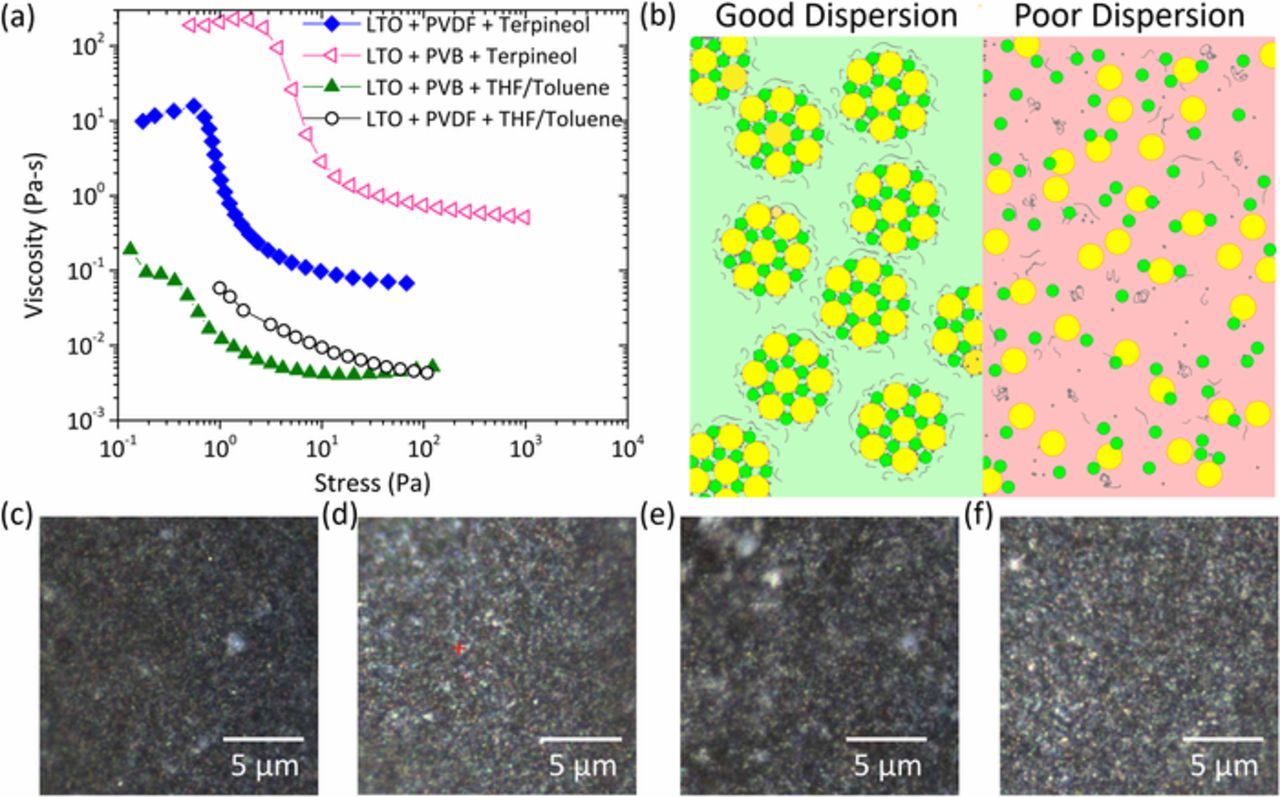
Figure 4. Rheological response of composite anode inks (a) viscosity as a function of shear stress. (b) Schematic diagram of ink microstructures in good and poor dispersions.
Characterization of composite electrodes
Stability and effect of polymeric binder in composite electrodes can also be explained via structural analysis. XRD analysis of different cathode inks cast on glass substrates revealed strong presence of pure LTO and LLZO phases. Unwanted Li2CO3 phases were detected in the PVDF containing systems upon exposure to air (Fig. 5b). The formation of Li2CO3 is ascribed to a weak binding between the PVDF and the cathodes which allows LLZO to react with air.
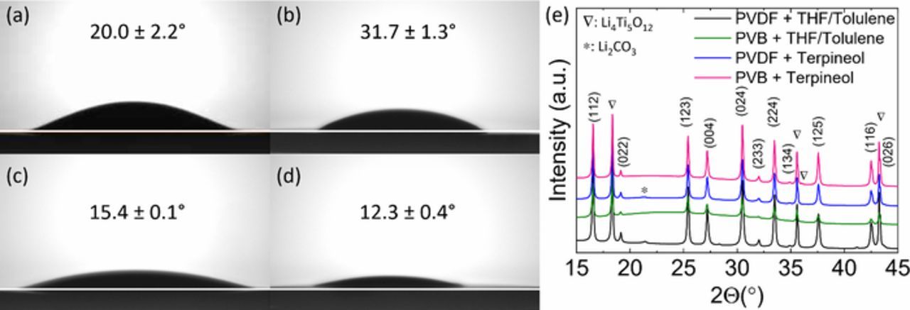
Figure 5. Contact angles of four cathode suspensions: (a) PVDF in THF/toluene; (b) PVB in THF/toluene; (c) PVDF in terpineol; (d) PVB in terpineol; (e) XRD patterns of the four cathodes measured with glass slide substrates. The suspensions of the cathodes were stored for three months after preparation.
The interfacial interactions between the electrode ink dispersions and the solid electrolyte play a significant role in determining the resultant electrode. Contact angle measurements of the four cathode suspensions on the ceramic LLZO electrolyte surface was performed to elucidate the wettability of the inks. Inks containing terpineol have a higher surface tension compared to the THF/Toluene inks (Fig. 3a). PVB-Terpineol containing electrode inks show the lowest contact angle (12.3 ± 0.4°), while the PVB-THF/Toluene containing inks show the largest contact angle (31.7 ± 1.3°) (Fig. 5a). This shows that the LLZO-ink interaction is much stronger for the terpineol inks and results in improved contact with the electrolyte. Improved wettability ensures better contact of the active materials with LLZO ensuring proper ion conduction and thus leads to better capacity performance of the electrodes. It should be noted that the contact angle measurements are carried out on composite inks while the surface tension measurements are carried out on the polymer solutions. Hence, we observe differences in contact angles while the surface tensions of polymer solutions converge to a similar value for PVB and THF/Toluene solvents irrespective of the polymer type.
Electron and ion transport in electrodes and between electrodes and electrolytes is weakened by poor bonding. The selection of binder and solvent plays a major role on electrode bonding. A pop-up stress tests was performed on electrodes containing PVDF and PVB binders. The average adhesion of the electrode prepared with PVDF binder and THF/Toluene solvent was found to be the least (≈0.03 MPa) while the electrode prepared with PVB binder and Terpineol solvent sustained the maximum force of 0.54 MPa (Fig. 6a). Electrodes with PVB binder are more strongly bound than the electrodes with PVDF binder. This is coincident with the ink's stability test, as the aggregation and inhomogeneity in electrodes with PVDF binder can cause delamination leading to low cell capacity. PVB contains non-polar butyral groups and polar hydroxy groups, showing advantages to mixtures. Polar OH-groups adhere to oxides (LLZO, LTO) and nonpolar butyral groups provide more adhesion to conductive carbon additives.59 The electrodes prepared with Terpineol solvent sustain higher forces than those with THF/Toluene solvent. As shown in Fig. 3b, the electrode slurries with the THF/Toluene solvent possess more aggregation, which results in greater active material and binder inhomogeneity. The electrodes are almost peeled off from the electrolytes for the PVDF binder system (Figs. 6b and 6d), but generally still hold their form for the PVB binder system (Figs. 6c and 6e).

Figure 6. (a) Pop-up stress test between cathodes and LLZO substrates. The digital images after pop-up test with cathodes prepared with (b) PVDF in THF/toluene; (c) PVB in THF/toluene; (d) PVDF in terpineol; (e) PVB in terpineol. The pellet size is 8 mm. Cathode weight and coating area were almost the same for the four pellets.
LLZO is known to undergo spontaneous proton exchange with Li+ when exposed to water and can form insulating carbonate products in air.60,61 Both of these interfacial transformations can cause an increase in the interfacial resistance of the cell and a decrease in lifetime. To evaluate the solvent's role on the interfacial chemistry of the solid electrolyte we submerged pristine electrolytes into each solvent for a short period of time (THF/Toluene and Terpineol) and subsequently dried the samples under vacuum. The samples were then sealed and transferred to XPS to avoid air contamination. In the C 1s spectra, four adventitious carbon contamination contributions are observed at 284.6 eV, 286.4 eV, 288.3 eV, and 289.7 eV, corresponding to C-C, C-O-C, O-C=O, and CO3, respectively (Fig. 7a). Since the pellets were polished in an air atmosphere, the characteristic peak of Li2CO3 is present. A noticeable increase in the carbonate is observed for the solvent treated LLZO in comparison with the pristine electrolyte. Furthermore, there was a pronounced difference between the terpineol carbonate layer (10.3%) and the THF/Toluene (4.2%) (Figs. 7b, 7c). Terpineol has a significantly higher boiling point (215°) than the THF/Toluene mixture and thus has a longer solvent evaporation time (Fig. 7c). To avoid carbonate layer growth, it is advantageous to have a fast solvent evaporation process.
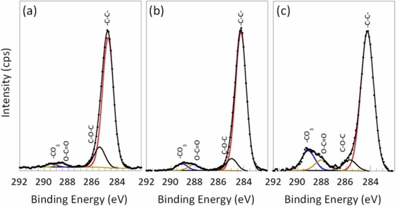
Figure 7. High-resolution C 1s spectra acquired on the LLZO pellets (a) pristine and immersed into THF/Toluene solvents (b) and Terpineol (c).
Conclusions
Ink engineering is leveraged to improve the performance of composite electrodes in ASSBs. Lithium titanate anodes achieve 3–4 × capacity increase (1.5 mAh/kg to ≥ 12 mAh/g) by tailoring the ternary component interactions within the ink (polymer|solvent|particles). Specifically, terpineol based inks showed improved ink stability and lower aggregate compared to the inks THF/Toluene inks. Subsequently, the effects of PVB and PVDF binders were investigated. PVB/Terpineol system shows stronger polymer-particle interaction leading to improved dynamic surface tension and rheology leading to improved electrode and capacity performance. Tailoring the ink composition also leads to improved wettability (12.3 ± 0.4°) and adhesion (0.54 MPa) at the solid|solid interface for the PVB/Terpineol based ink. Characterization of the electrode and the interface showed that PVDF and terpineol solvent lead to the formation of Li2O3. Faster solvent removal and improved binding properties can potentially mitigate this effect. Employing ink engineering with interfacial modification is needed to achieve scalable production of high-performance ASSBs.
Acknowledgment
This material is based upon work supported by the National Science Foundation under grant No. 1847029 (W.Z.) and No. 1727863 (M.D.). The authors acknowledge the Vanderbilt Institute of Nanoscience and Engineering (VINSE) for access to their shared characterization facilities. The authors acknowledge support from the Ralph E. Powe Junior Faculty Enhancement Award.
ORCID
Marm B. Dixit 0000-0002-9599-9288
Kelsey B. Hatzell 0000-0002-5222-7288