Abstract
Dual-graphite cells have been proposed as electrochemical energy storage systems using graphite as both, the anode and cathode, whereas the electrolyte cations intercalate into the negative electrode and the electrolyte anions intercalate into the positive electrode during charge. On discharge, cations and anions are released back into the electrolyte. In this contribution, we present highly promising results for "dual-ion cells" based on intercalation of bis(trifluoromethanesulfonyl)imide anions into a graphite cathode from an ionic liquid-based electrolyte, namely N-butyl-N-methylpyrrolidinium bis(trifluoromethanesulfonyl)imide (Pyr14TFSI). As the compatibility of this ionic liquid with graphitic anodes is relatively poor, metallic lithium and lithium titanate (Li4Ti5O12) are used as anode. As both cations and anions participate in the charge/discharge reaction and other anode materials than graphite are possible, we propose the name "dual-ion cells" for these systems. The cell performance was studied in terms of cut-off voltage, temperature, cycling stability, self-discharge and rate performance. Depending on the cut-off voltage and temperature, coulombic efficiencies of more than 99 % and specific discharge capacities exceeding 100 mAh g−1 (based on graphite cathode weight) were achieved. Furthermore, this system provides an excellent cycling stability and capacity retention above 99 % after 500 cycles, outperforming reported organic solvent-based dual-graphite or dual-ion cells.
Export citation and abstract BibTeX RIS
Graphite is a redox-amphoteric intercalation host and therefore cations and anions can be electrochemically intercalated at different potentials yielding so-called donor-type or acceptor-type graphite intercalation compounds (GICs).1,2 Currently, the predominantly used donor-type GIC is LiCx. The LiCx/Cx redox couple is the major active compound for state-of-the-art negative electrodes in lithium ion batteries.3–7
Compared to the limited number of cationic intercalation guests, there is a broad spectrum of different anions capable to form acceptor-type GICs. Examples are hexa- or tetrafluoride guest species, e. g. PF6−, AsF6− or BF4−,8–10 hexa- or tetrachloride com-pounds like AlCl4−, GaCl4− or TaCl6−11–13 and oxide based guests including SO4−, NO3− or ClO4−.14–17 Additionally, also carbon-based anions with relatively large ionic radii, such as trifluoroacetate (CF3COO−),18 perfluorooctanesulfonate (C8F17SO3−),19 tris(trifluoromethanesulfonyl) methide ((CF3SO2)3C−) or bis-(trifluoromethanesulfonyl) imide ((CF3SO2)2N−)20–22 are capable to form acceptor-type GICs.
In 1938, Rüdorff and Hofmann developed the first ion transfer or rocking chair cell based on the shuttling of HSO4− anions between two graphite electrodes (Figure 1a).14 This cell can be considered as the ancestor of the well-known lithium-ion cell, where lithium cations are transferred between two insertion electrodes during the charge/discharge process (Figure 1b).3 In the 1990s, a rechargeable electrochemical energy storage system, using graphite as positive and negative electrode material in combination with a non-aqueous electrolyte has been introduced by McCullough et al.23–26 and Carlin et al.27,28 Carlin et al. investigated the reductive and oxidative intercalation of different cations and anions from ionic liquid-based electrolytes (without any additional lithium salt), such as 1-ethyl-3-methylimidazolium hexafluorophosphate (EMI+PF6−). This system, a so-called dual-graphite cell, was based on the simultaneous intercalation of EMI+ cations into the graphite anode and PF6− intercalation into the graphite cathode during charge (Figure 1c). The concept of anion intercalation-based energy storage devices was under further investigation by Seel and Dahn,29,30 where the intercalation of PF6− anions into the graphite cathode and Li+ intercalation into the graphite anode from organic solvent based electrolytes, such as sulfones or mixtures of carbonates, was examined and characterized (Figure 1d). More recently, different types of anion intercalation-based energy storage systems have been in the focus of research. On the one hand, there are the so-called hybrid supercapacitors, applying a graphite positive electrode in combination with an activated carbon negative31 and on the other hand, there are systems based on a graphite cathode and a metal oxide anode, e. g., TiO2 or MoO3, working at potentials above 1 V vs. Li/Li+.32–34 The latter systems may be considered as safe energy storage systems as there is a very limited possibility of oxygen generation from the cathode (as in the opposite case of transition metal oxides in lithium-ion batteries during overcharge) and as the working potential of the anode is far away from lithium deposition at the anode.
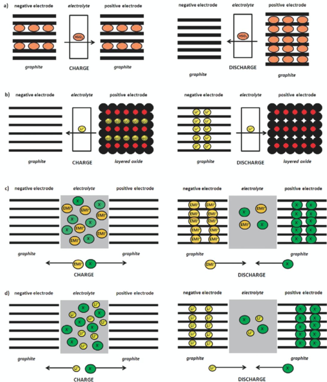
Figure 1. Principle of operation for different electrochemical energy storage devices. (a) HSO4− ion transfer cell with graphite as positive and negative electrode. (b) Lithium-ion cell with graphite anode and layered oxide cathode. (c) Dual-graphite cell with graphite as positive and negative electrode and ionic liquid-based electrolyte (e. g. EMI+X−), based on EMI+ cation and X− anion intercalation. (d) Dual-graphite cell with graphite as positive and negative electrode and organic solvent-based electrolyte, based on anodic Li+ and cathodic anion intercalation.
However, a major drawback is the limited stability of the organic electrolytes vs. oxidation at the high working potentials of the graphite positive electrode. As during anion intercalation the cathode potential approaches up to 5 V vs. Li/Li+ and more, the organic solvent-based electrolyte decomposes, resulting in insufficient coulombic efficiency of the system and continuous electrolyte degradation. A further issue concerning the organic solvent-based electrolytes is the fact that solvent co-intercalation into graphite can occur, resulting in the formation of ternary phases Cn+(solv)yX−,2 which can subsequently lead to graphite exfoliation. The decomposition of these intercalated solvent molecules inside the graphite interlayer gaps results in gas formation and structural disorder, which may lead to destruction of the electrode integrity.35
In this contribution, highly promising results for "dual-ion cells" taking advantage of anion intercalation into graphite from an ionic liquid (IL) based electrolyte are presented. In particular, ionic liquids belonging to the group of N-alkyl-N-methylpyrrolidinium bis(perfluoroalkylsulfonyl)imides provide several beneficial properties compared to the state-of-the-art organic solvent based electrolytes, such as a broad electrochemical stability window with a high stability vs. oxidation, low safety hazards (a very low volatility at ambient pressure and nonflammability), a broad liquid range, high thermal stability and an overall good compatibility with existing lithium ion battery electrodes.36–40 Therefore, the ionic liquids are a promising candidate to improve the safety properties of particularly large scale lithium-based batteries.41 The (partially) reversible intercalation of the bis(trifluoroalkylsulfonyl)imide (TFSI−) anion into graphitic carbon from organic solvent-based electrolytes has been shown already in 1995.21 The reaction proceeds via various intercalation (anodic currents) and de-intercalation (cathodic currents) stages. Furthermore, a clear difference between the threshold potential of the first and second sweep of the anion intercalation process could be observed (Figure 2).

Figure 2. Cyclic voltammogram (first two cycles) of a graphitic carbon fiber P100 (FMI composites, Amoco, Union Carbide) in EC:DMC 1:1, 1M LiTFSI; scan rate: 2 mV s−1.
As ILs are molten salts, only composed of ions and not containing organic solvent molecules, they can be selected as the source of the guest anion and the issue of solvent co-intercalation2,42–49 at both sides, the anode and the cathode at high cell potentials, can be precluded. Especially the broad electrochemical stability window and the fact, that these systems are only composed of ions, make ILs extraordinary candidates for energy storage devices based on ion intercalation. However, the compatibility of these ILs with graphitic negative electrodes is poor, as there is no effective solid electrolyte interphase (SEI) formation as in the case of organic solvent-based electrolytes.50–57 Thus, the large IL-cations can be co-intercalated together with lithium ions, thus causing graphite exfoliation.58 Therefore, alternative anode materials are investigated, namely metallic lithium and Li4Ti5O12 (LTO), both of them displaying a good compatibility with pyrrolidinium-based ionic liquids.41,59 Considering the lithium metal anode, ILs provide a fundamental difference to the organic solvent-based electrolytes, as the solvent and the electrolyte salt are the same. This, in turn could lead to the formation of a more uniform SEI and therefore to an enhanced charge/discharge cycle life.41 Consequently, we rename the "dual-carbon" or "dual-graphite cell" in "dual-ion cell", where both cations and anions of the electrolyte participate in the charge/discharge reaction and various anode and cathode materials may be employed (Figure 3). Recently, we reported that specific energies of more than 100 Wh kg−1 (with respect to the weight of the graphite cathode) are possible for these systems, making it therefore an option for stationary energy storage.60,61
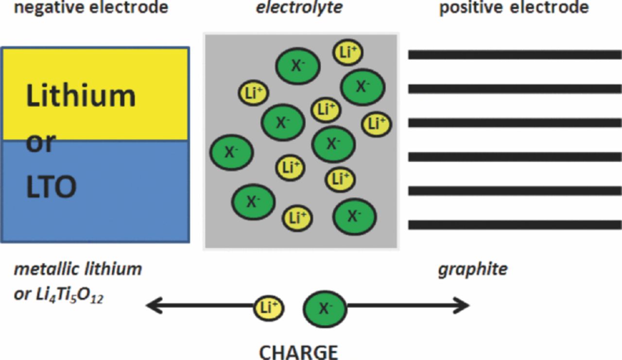
Figure 3. Principle of operation of a dual-ion cell with a graphite positive electrode and a metallic lithium or Li4Ti5O12 negative electrode during the charge process.
The electrochemical system investigated in this work is based on the intercalation of bis(trifluoromethanesulfonyl)imide (TFSI−) anions into the graphite positive electrode and either the lithium deposition on metallic lithium or the lithium ion insertion into LTO as negative electrode reaction during the charge process (Figure 3). During the discharge process, both ions are released back into the electrolyte. As a consequence, the lithium salt concentration of the electrolyte during charge/discharge operation is changing continuously, influencing the electrolyte conductivity, which is therefore varying with the state of charge.40,62 Both ions derive from the electrolyte, containing lithium bis(trifluoromethanesulfonyl)imide (LiTFSI) as electroactive salt in the ionic liquid N-butyl-N-methylpyrrolidinium bis(trifluoromethanesulfonyl)imide (Pyr14TFSI). This electrolyte provides an exceptional stability, especially at high cell voltages.63 The major difference compared to the work of Carlin et al.27 is not only the use of a pyrrolidinium-based ionic liquid, but also the fact that the IL-cation does not take part in the intercalation process at the anode as no graphitic carbon anode is used. Instead, the lithium salt is involved in the redox process. The graphite positive electrodes were prepared using an aqueous processing route with the environmentally friendly binder sodium carboxymethylcellulose (CMC),64,65 which provides a good compatibility and stability for the anion intercalation. It should be noted that at contrast to lithium-ion battery cathode materials, graphite as positive electrode material does not suffer from hydrolysis during aqueous processing with CMC. The electrochemical performance of this dual-ion system has been investigated by variation of the cut-off voltage and in terms of temperature, rate performance, self-discharge and cycling stability.
Experimental
Electrode tapes for the positive electrode were prepared using a composition of 90 wt% of synthetic graphite TIMREX KS6 (TIMCAL, d50 = 3.2 μm/d90 = 6.0 μm), 5 wt% of conductive carbon black agent C-nergy Super C65 (TIMCAL) and 5 wt% of sodium carboxymethylcellulose (CMC) as binder (Walocel CRT 2000 PPA 12, Dow Wollf Cellulosics). Prior to the dispersion of the solid compounds, the binder polymer was dissolved in de‑ionized water to obtain a 2.5 wt% solution. The appropriate amount of Super C65 was added to the binder solution and the mixture was further equilibrated. Afterwards, KS6 graphite was introduced into the paste, followed by a high-energy dispersion step (T 25 Ultra Turrax, 1 hour, 5000 rpm) to eliminate agglomerates and homogenize the mixture. The paste was cast on a freshly etched aluminum foil (30 μm, purity > 99.9 %, etched with 5 wt% KOH) applying a standard lab-scale doctor-blade technique. The gap of the doctor blade was set to 120 μm wet film thickness, leading to an average mass loading of 2.5 mg cm−2. After casting, the tapes were transferred into an atmospheric oven and dried for 12 hours at 80°C. Electrodes with a diameter of 12 mm were cut out and a further drying step was performed under an oil-pump vacuum at 170°C for 24 hours. Thereafter, the electrodes were stored in an Argon filled glove box (UniLab, MBraun) with water and oxygen contents below 1 ppm.
Tapes of Li4Ti5O12 (LTO, Sigma-Aldrich) as negative electrode were prepared using a ratio of 85 wt% active material, 10 wt% of conductive agent Super C65 and 5 wt% of poly(vinylidene)fluoride binder (PVdF, Kynar 761). Prior to the dispersion of the solid materials, the binder polymer was dissolved in anhydrous, high-purity N‑methyl pyrrolidone (NMP, Acros-Organics) to obtain a 4 wt% solution. The electrode preparation followed the procedure described above. The paste was cast on a freshly etched aluminum foil using a doctor blade gap of 200 μm. This resulted in an average mass loading of 6 mg cm−2, which corresponds to a 3 times oversized LTO anode compared to the capacity of the graphite cathode. This mass balance avoids any over-reduction of the anode, with unpredictable results on performance and safety: This is necessary, as we are investigating completely new electrode/electrolyte combinations. Electrodes were cut out, dried and stored as described before.
Electrochemical investigations were carried out in lab-scale Swagelok type T‑cells with a three-electrode configuration. The measurements were performed using either high‑purity metallic lithium foil (Chemetall) or the LTO composite as negative electrodes. Lithium was used in all cases as reference electrode in the three-electrode cell setup. As separator a glass microfiber filter (Whatman, grade GF/D) drenched with 100 μL of electrolyte was used. As electrolyte, a mixture of N-butyl-N-methylpyrrolidinium bis(trifluoromethanesulfonyl)imide (Pyr14TFSI, Solvionic, purity: 99.9 %) with 1M of lithium bis(trifluoromethanesulfonyl)imide (LiTFSI, 3M, purity: 99.95%) as conductive and electroactive salt (molar ratio of LiTFSI:Pyr14TFSI = 1:3.34) was applied. Prior to the application, the received IL was additionally dried, applying an ultra-high vacuum procedure, resulting in a water content of less than 10 ppm, determined by Karl Fischer titration.
Cyclic voltammetry was performed with a scan rate of 100 μV s−1 using a VMP multichannel constant voltage - constant current system (Biologic Science Instrument, France). Charge/discharge cycling was performed on a multichannel Maccor 4300 battery test system. After cell assembly the cells were equilibrated at room temperature (20°C) for 24 hours. The charge and discharge steps were performed using a constant current setup which corresponds to a constant current rate of 50 mA g−1, determined by the weight of the graphite positive electrode. Constant current and constant voltage charge/discharge cycling was performed by constant current charging the cell to the upper cut-off voltage, followed by a constant voltage step for a defined amount of time (15 min, 30 min, 60 min and 120 min). Discharge was performed using constant current in all cases. The charge/discharge current rate investigations were performed using the same current rate for both charge and discharge, whereas the discharge current rate investigations were performed by using always the same charge current of 10 mA g−1 and different discharge current rates. For the metallic lithium anode based cells, the ion intercalation/plating process (charge) was performed up to cut-off voltages in the range of 4.80 to 5.30 V while for the de‑intercalation/stripping process (discharge) a cut-off voltage of 3.40 V was chosen. The corresponding cut-off voltages of the cells using LTO as anode were 3.20 V to 3.80 V and 1.50 V, respectively. The charge/discharge cycling experiments at higher temperatures were performed in climatic chambers at 40°C and 60°C, respectively.
Results and Discussion
First cycle "activation" for anion intercalation and influence of the cut-off voltage
In order to examine the reversibility of the TFSI− anion intercalation/de‑intercalation processes into graphite and the influence of the upper cut-off voltage on the electrochemical performance of the dual-ion cells, a systematic investigation for various cut-off voltages was performed.
Figure 4 displays the first five cycles of a cyclic voltammogram for the metallic lithium/KS6‑graphite dual-ion cell (further abbreviated as Li/KS6) with 1M LiTFSI-Pyr14TFSI electrolyte. The upper cut-off voltage was chosen to be 5.40 V; the applied scan rate was 100 μV s−1. Several current peaks related to anion intercalation and de-intercalation of the TFSI− anions can be observed (cf.21). In the first cycle, the anion uptake begins at a cell voltage of about 4.80 V, whereas for the second and ongoing cycles the anion intercalation already starts at a lower voltage (about 4.40 V). In addition, the shape of the current curve, representing the anion uptake, strongly differs from the first cycle to the following ones. This observation indicates that during the first anion uptake a kind of "activation" or "formation" takes place, followed by a more reversible and reproducible behavior afterwards. This process is assumingly required to prevail against a kinetic hindrance. This may be related to a kind of opening process of the partially closed interlayer gaps at the graphite surface. Small graphite particles such as KS6 have been prepared by milling; the mechanical impact of milling may lead to graphene layer wrinkling and partial closure of the graphite interlayer gaps at the surface. Considering the large TFSI− anion, the kinetic hindrance is not surprising. Another possible source of kinetic hindrance is poor wetting due to insufficient porosity.66 After the first intercalation process and the related dimensional changes in the composite electrode, the porosity is sufficient. However, in any case this formation process seems to be limited to the first anion intercalation. In the ongoing cycles, a very similar shape for the anion intercalation and de-intercalation curves is obtained, indicating a good reversibility of the process and a kinetically less hindered anion uptake and release from the graphite. During anion intercalation two broad peaks in the cell voltage range of 4.40 to 4.80 V and 4.85 to 5.25 V can be observed, whereas during de-intercalation several peaks are observed in the voltage range of 4.90 to 3.90 V. The strong current increase in the upper cell voltage range of 5.30 to 5.40 V could be due to electrolyte decomposition reactions at these high cell voltages. This interpretation is confirmed by a strong decrease of the coulombic efficiency at 5.30 V, which will be discussed in more detail below (compare Table I). The occurrence of several current peaks for the TFSI− anion uptake and release in the voltamogramm clearly indicate a stage formation mechanism with multiple coordination possibilities for the anion in the graphite structure. These staging effects are well known for electrochemical lithium intercalation into graphite3,67–70 and for the PF6− intercalation into graphitic carbons.29
Table I. Correlation of upper cut-off voltage to the discharge capacity and coulombic efficiency for the metallic lithium/KS6-graphite dual-ion cell (left) and the LTO/KS6-graphite dual-ion cell (right). Values for the discharge capacity and coulombic efficiency of the 50th cycle of the constant current charge/discharge cycling experiments are obtained from the constant current cycling data, displayed in Figure 4.
| Lithium/KS6 graphite dual-ion cell | LTO/KS6 graphite dual-ion cell | ||||
|---|---|---|---|---|---|
| Cut-off | Discharge | Coulombic | Cut-off | Discharge | Coulombic |
| voltage/ | capacity/ | efficiency/% | voltage/ | capacity/ | efficiency/ |
| V | mAh g−1 | % | V | mAh g−1 | % |
| 4.80 | 36.6 | 99.4 | 3.20 | 27.7 | 99.6 |
| 4.90 | 42.2 | 99.4 | 3.30 | 35.2 | 99.5 |
| 5.00 | 50.1 | 99.4 | 3.40 | 38.9 | 99.3 |
| 5.10 | 62.6 | 99.1 | 3.50 | 44.0 | 99.2 |
| 5.20 | 84.7 | 96.3 | 3.60 | 54.9 | 99.0 |
| 5.30 | 96.5 | 90.3 | 3.70 | 72.9 | 98.2 |
| 3.80 | 84.5 | 97.4 | |||
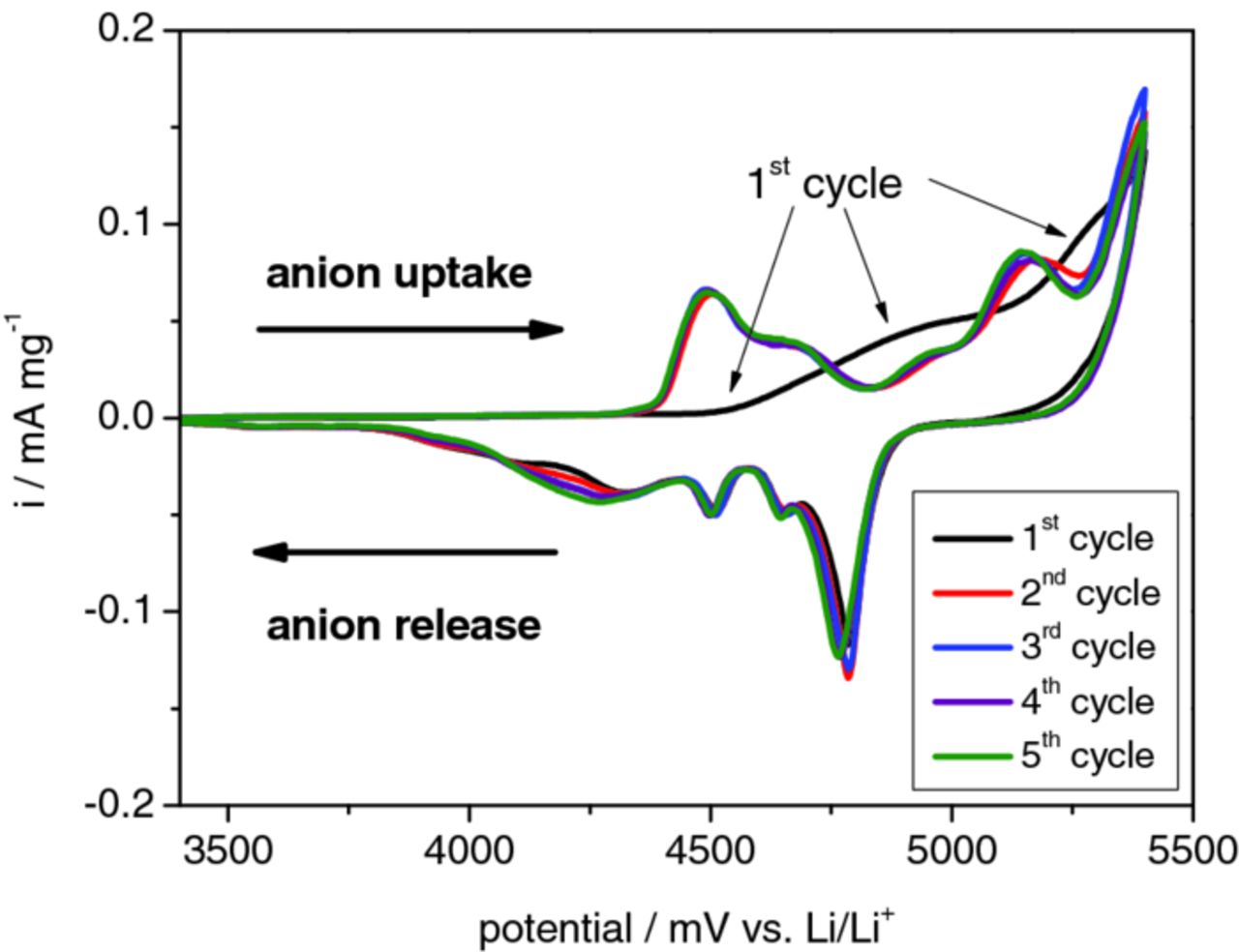
Figure 4. Cyclic voltammogram of a dual-ion cell with a metallic lithium anode, KS6 graphite cathode and Pyr14TFSI ionic liquid electrolyte with 1 M LiTFSI. The first five cycles of anion intercalation and de-intercalation in the cell voltage range of 3.40 to 5.40 V using a scan rate of 100 μV s−1 are depicted.
Figure 5 displays the cell voltage vs. specific capacity profiles for (a) the Li/KS6 dual‑ion cell and (b) the LTO/KS6-graphite dual-ion cell (further abbreviated as LTO/KS6) during selected cycles of the constant current charge/discharge process (1st, 2nd and 50th cycle). The upper cut-off voltage has been chosen to be 5.00 V for the Li/KS6 system (Figure 5a) and 3.40 V for the LTO/KS6 dual-ion cell (Figure 5b). For both systems, the difference in charge curves during the anion intercalation in the first, second and the following cycles (represented by the 50th cycle) is clearly observable. As discussed, the first cycle is different due to a kinetic hindrance. The opening process of the graphite interlayer gaps will be most likely dependent on the specific surface area of the graphite particles71 and in particular on the fraction of prismatic surfaces,72–74 as anion intercalation can only take place through prismatic-surface sites, as like for lithium ions.75 For the Li/KS6 dual-ion cell, the anion intercalation in the first cycle starts at about 4.80 V, whereas for the following cycles the onset cell voltage for the anion uptake is decreased to about 4.40 V. A similar trend can be recognized in the LTO/KS6 system. Here, in the first cycle, the TFSI− intercalation starts at about 3.20 V, which is decreased to 2.88 V for the following charge/discharge cycles. Additionally, a voltage drop is observed for the discharge reaction. In general, the TFSI− anion intercalation displays a relatively large polarization compared to the relatively small effects observed for the lithium intercalation into graphite. This effect could assumingly be related to the large ionic radius of the TFSI− anion and therefore the reduced mobility compared to lithium ions. The discharge/de‑intercalation reaction for the Li/KS6 system occurs in a voltage range of 4.70–4.00 V, and between 3.00 to 2.40 V for the LTO based dual-ion cell. The obtained capacities start at lower values and then increase to a certain maximum value; depending on the current rate, the cut-off voltage and the temperature. Figure 5 depicts this effect for both systems (Li/KS6 and LTO/KS6) at room temperature (20°C), whereas in Figure 9 the temperature dependence is illustrated. This increase in capacity with cycling is similar to the results observed with graphite and LiFePO4 electrodes manufactured with CMC-binders and ionic liquids,38,76,77 approaching the maximum capacity only after about 10 to 15 cycles. This effect may be explained by an insufficient penetration of the electrodes by the viscous electrolyte or by a limited electrode porosity, due to the rigidness of the cellulose binder backbone.78
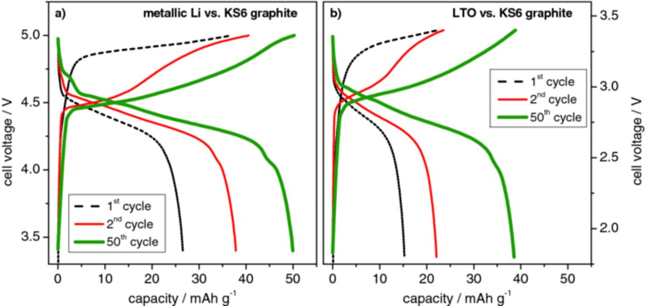
Figure 5. Representative voltage profiles displaying the 1st, 2nd and 50th cycle of the (a) metallic lithium/KS6-graphite dual-ion cell with an upper cut-off voltage of 5.0 V and the (b) LTO/KS6-graphite dual-ion cell with an upper cut-off voltage of 3.40 V.

Figure 9. Cell voltage vs. specific capacity profiles for the metallic lithium/KS6-graphite dual-ion cell during selected cycles of the constant current charge/discharge process at different temperatures. (a) 1st and 2nd cycle at 20°C, (b) 1st and 2nd cycle at 40°C, (c) 1st and 2nd cycle at 60°C and (d) com-parison of the 50th cycle at different temperatures (upper cut-off voltage: 5.0 V; current rate: 50 mA g−1).
To further identify the effect of the upper cut-off voltage on the discharge capacity and coulombic efficiency, constant current charge/discharge investigations with different cut-off voltages were performed for both dual-ion systems. Figure 6 displays representative cell voltage vs. specific capacity profiles for the 50th cycle, depicting the charge and discharge processes of (a) the Li/KS6 and (b) the LTO/KS6 dual-ion cells. The metallic lithium based system was investigated in the upper cell voltage range from 4.80 to 5.30 V, whereas the cycles at three different cut-off voltages, namely 4.80 V, 5.10 V and 5.30 V, are displayed in Figure 6a. The LTO/KS6 dual-ion cell was examined in the upper cell voltage range from 3.20 to 3.80 V, whereas the voltage profiles for the cut-off voltages of 3.20 V, 3.50 V and 3.80 V are depicted in Figure 6b. Table I summarizes the corresponding values for the discharge capacity and coulombic efficiency for both systems at the different cut-off voltages. For both dual-ion systems it can be observed that by increasing the cut-off voltage a higher anion uptake/specific capacity of the graphite can be achieved. In the Li/KS6 dual-ion cell, a discharge capacity of about 50 mAh g−1 at a cut-off voltage of 5.00 V is almost doubled to about 96 mAh g−1 by increasing the cut-off voltage to 5.30 V. For the LTO based system, the discharge capacity can be increased from about 28 mAh g−1 to 85 mAh g−1 by increasing the cut-off voltage from 3.20 V to 3.80 V. Consequently, a clear trend for the coulombic efficiencies can be also observed, as by increasing the cut-off voltage, the efficiencies slightly decrease. With the Li/KS6 couple and a cut-off voltage of 5.00 V, a coulombic efficiency of 99.4% can be achieved while at 5.10 V a still remarkable efficiency of 99.0 % is obtained (Table I). At 5.30 V, the efficiency decreases to 90%. The same trend is present in the LTO/KS6 system. Here, efficiencies in the range of 99.6 % to 99.0 % can be achieved between a cell voltage of 3.20 V and 3.60 V. Again, at higher cell voltages the efficiency decrease becomes more distinct. This decrease at higher cell voltages could be caused by different effects, e. g. stability problems of the graphite intercalation compound, degradation of the graphitic particle structure, decomposition of the ionic liquid electrolyte at the cathode/electrolyte interface or limited oxidation stability of the intercalated anions, resulting in TFSI− anion decomposition. We believe that the latter is the most probable assumption. The corrosion of the aluminum current collector by the ionic liquid electrolyte can be mostly excluded as it is known that no detectable faradaic reactions at the aluminum surface occur up to 5.4 V vs. Li/Li+ in the presence of Pyr14TFSI - LiTFSI electrolyte (at 20°C).79 However, the corrosion of the aluminum current collector cannot be completely excluded and becomes even more serious at elevated temperatures.80
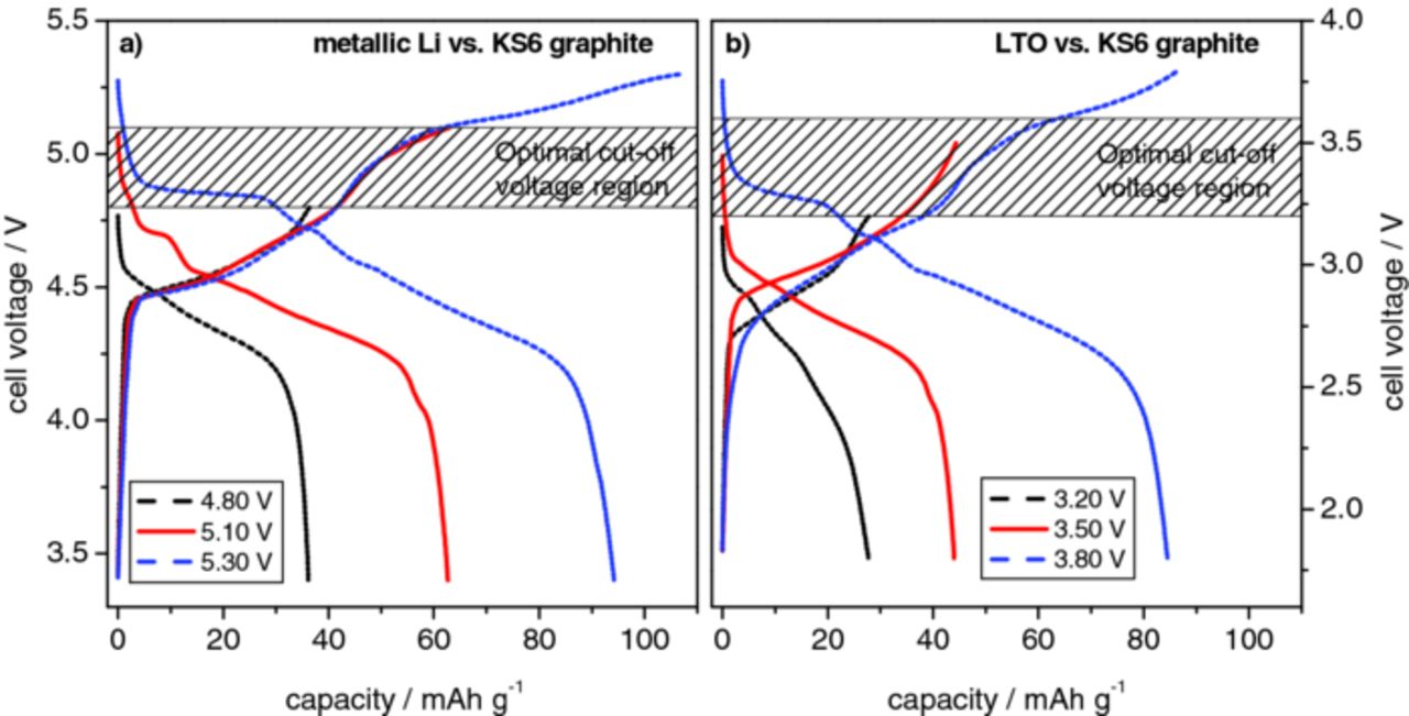
Figure 6. Representative voltage profiles displaying different cut-off voltages. (a) Metallic lithium/KS6-graphite dual-ion cell with upper cut-off voltages of 4.80 V, 5.1 V and 5.30 V. (b) LTO/KS6-graphite dual-ion cell displaying upper cut-off voltages of 3.20 V, 3.50 V and 3.80 V.
The aim of the previously described investigations was to identify the optimal cut-off voltage for both dual-ion cell systems. The result is that a compromise between high discharge capacities and high efficiencies is necessary in order to minimize decomposition or degradation reactions of the electrolyte and the positive graphite electrode. In summary, the optimal upper cut-off voltage ranges are 4.80 to 5.10 V for the Li/KS6 system (Figure 6a) and 3.20 to 3.60 V for the LTO/KS6 dual-ion cell (Figure 6b).
Charge/discharge rate investigations and influence of a constant voltage step
To examine the influence of the current rate and constant voltage charge step on the electrochemical performance of the dual-ion systems, systematic investigations were performed.
Figure 7 displays the rate performance of a Li/KS6 dual-ion cell with an upper cut-off voltage of 5.0 V. In Figure 7a, both, charge and discharge current rates were varied, whereas in Figure 7b, only the influence of a varying discharge current rate was investigated. Table II shows the obtained discharge capacities. As the precise nominal capacity of the TFSI‑‑graphite intercalation compound, Cn+TFSI−, is unknown at present, all rate values are represented as specific current (in mA g−1). A specific current of 100 mA g−1 would correspond to a C-rate of 1, assuming a discharge capacity of 100 mAh g−1 can be reached (discharge capacities of about 100 mAh g−1 are achieved at high cell voltages or increased temperatures; see chapter 3.1 and 3.3, respectively). The charge/discharge rate performance tests revealed discharge capacities of about 56 mAh g−1 for a relatively low specific current of 10 mA g−1, whereas the discharge capacity decreased to less than 40 mAh g−1 for a high specific current of 500 mA g−1. In the discharge current rate investigation, the de-intercalation capacities were higher than in the charge/discharge rate investigation. In fact, at high discharge current rates of 200 mA g−1, discharge capacities exceeding 50 mAh g−1 were obtained. Therefore, it can be concluded that the anion intercalation (=charge) process is the capacity-determining step, as high discharge capacities can be obtained even at high de‑intercalation current rates if the anion intercalation is performed at lower current rates.
Table II. Influence of the specific current rate on the discharge capacity for the charge/discharge current rate performance (same current rate for both charge and discharge) and discharge current rate performance (constant charge current of 10 mAg−1) for the metallic lithium/KS6-graphite dual-ion cell. Upper cut-off voltage: 5.0 V (Obtained from constant current cycling data, displayed in Figure 5).
| Charge/discharge rate performance | Discharge rate performance (charge current: 10 mA g−1) | ||
|---|---|---|---|
| Current | Discharge | Discharge | Discharge |
| rate/mA g−1 | capacity/mAh g−1 | current/mA g−1 | capacity/mAh g−1 |
| 10 | 55.7 | 10 | 55.7 |
| 20 | 53.6 | 20 | 54.3 |
| 50 | 50.1 | 50 | 53.6 |
| 100 | 47.5 | 100 | 53.4 |
| 200 | 44.4 | 200 | 52.8 |
| 500 | 39.6 | 500 | 45.0 |
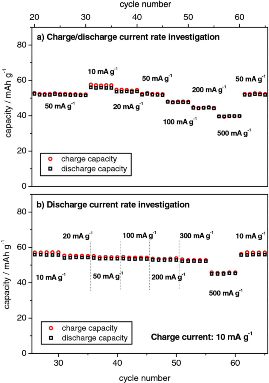
Figure 7. Charge/discharge current rate performance (same current density for both charge and discharge) (panel a) and discharge current rate performance (constant charge current of 10 mA g−1) (panel b) for the metallic lithium/KS6-graphite dual-ion cell (upper cut-off voltage: 5.0 V).
Figure 8 and Table III display the effect of a constant voltage (CV) step in the constant current – constant voltage charge/discharge investigations for the Li/KS6 dual-ion cell. In these experiments, the cells were charged at constant current (CC, 50 mA g−1) to a cell voltage of 5.0 V and then hold at this potential for a certain time (constant voltage step) prior to be discharged with constant current again. Figure 8a displays the specific charge capacities, obtained by the experiments with a constant voltage step of 2 hours. The total charge capacity can be subdivided into two parts representing the capacity obtained during constant current and during the constant voltage step, respectively. An additional charge capacity of about 10 mAh g−1 is obtained by a 120 minute constant voltage step (Figure 8a). For a constant voltage step of 30 minutes (Figure 8b) at a cut-off of 5.0 V, the specific current decreases relatively fast from 50 mA g−1 to about 5 mA g−1 within 30 minutes. Figure 8c displays the voltage and specific current profile for a constant voltage step of 2 hours, showing that the specific current decreases from 50 mA g−1 to about 1 mA g−1. Table III depicts the discharge capacities that can be obtained by different constant voltage step times and at different cut-off voltages. In the case of a cut-off voltage of 5.0 V, even relatively short constant voltage holding steps of 15 minutes lead to a corresponding discharge capacity of about 56 mAh g−1, which is detected in cells charged with a much lower specific current (at 10 mA g−1, see Table II). Constant voltage steps of one hour lead to a capacity of even ca. 60 mAh g−1 at 5.0 V cut-off. However, longer voltage holding steps of up to 2 hours, only slightly increase the discharge capacity. A discharge capacity increase after the constant voltage step is observed for all cut-off voltages.
Table III. Influence of different constant voltage step times at various cut-off voltages on the discharge capacity of the metallic lithium/KS6-graphite dual-ion cell (current rate for constant current charge/discharge step: 50 mA g−1), obtained from constant current/constant voltage investigation, displayed in Figure 6.
| Cut-off | Constant voltage (CV) | Discharge |
|---|---|---|
| voltage/V | step time/min | capacity/mAh g−1 |
| 0 | 50.1 | |
| 15 | 55.9 | |
| 5.00 | 30 | 57.6 |
| 60 | 60.4 | |
| 120 | 60.9 | |
| 4.80 | 0/60/120 | 36.6/44.8/45.0 |
| 4.90 | 0/60/120 | 42.2/48.5/49.0 |
| 5.10 | 0/60/120 | 62.6/80.5/81.7 |
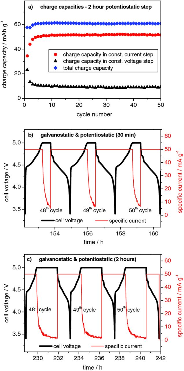
Figure 8. Influence of the constant voltage step on the electrochemical performance of the metallic lithium/KS6-graphite dual-ion cell (upper cut-off voltage: 5.0 V; current rate: 50 mA g−1). (a) Representative charge capacities for constant current (CC)/constant voltage (CV) investigation with 2 hours of constant voltage. (b) Representative voltage und current profiles for 30 min of constant voltage step. (c) Representative voltage und current profiles for 2 hours of constant voltage step.
Influence of the temperature on the electrochemical performance
To determine the influence of the temperature on the electrochemical performance of the dual-ion systems, a systematic investigation at 20°C, 40°C and 60°C, was performed.
Figure 9 displays the cell voltage vs. specific capacity profiles for the Li/KS6 dual-ion cell during selected cycles (1st, 2nd and 50th) of the constant current charge/discharge process at these different temperatures, whereas Table IV lists the corresponding specific discharge capacities and coulombic efficiencies. The cut-off voltage was set to 5.0 V. At a first glance, it is obvious that by increasing the temperature, increased TFSI− anion intercalation and, therefore, discharge capacity is achieved. Whereas at 20°C a discharge capacity of only 50 mAh g−1 was obtained with this cell setup, a more than doubled value (105 mAh g−1) was recorded by increasing the temperature to 60°C. Furthermore, Figure 9d clearly indicates different shapes of the voltage profile depending on the temperature, exemplarily regarding the 50th charge/discharge cycle. At higher temperatures, more and clearer distinguishable stages for intercalation and de-intercalation are observable. Figure 10 shows a better visual identification of the different voltage regions of intercalation and de-intercalation of the TFSI− anions, by plotting the cycling curves of the 1st and 50th constant current charge/discharge cycle as differential capacity profiles. Whereas at 20°C only a single broad "peak" representing intercalation stages in the range of 4.4 to 5.0 V and two peaks corresponding to the de-intercalation at about 4.7 V and from 4.6 to 4.0 V can be observed, more stages appear at higher temperatures. At 60°C three main intercalation stages are visible in the voltage ranges 4.35 to 4.65 V, 4.75 to 4.85 V and 4.90 to 5.0 V, with the most dominant in the highest voltage range. Four stages (ca. 4.9 V, from 4.85 to 4.7 V, ca. 4.6 V and from 4.5 to 4.0 V) are observed for the anion de-intercalation process.
Table IV. Specific discharge capacities and coulombic efficiencies for selected cycles of the metallic lithium/KS6-graphite dual-ion cell at 20°C, 40°C and 60°C, obtained from constant current cycling data, displayed in Figure 7.
| Discharge capacity | Coulombic efficiency/% | ||||
|---|---|---|---|---|---|
| Temperature/°C | (50th cycle)/mAh g−1 | 1st cycle | 2nd cycle | 3rd cycle | 50th cycle |
| 20 | 50.1 | 71.8 | 93.2 | 95.3 | 99.4 |
| 40 | 67.0 | 76.6 | 94.4 | 96.0 | 99.1 |
| 60 | 105.5 | 74.6 | 91.2 | 94.0 | 95.8 |
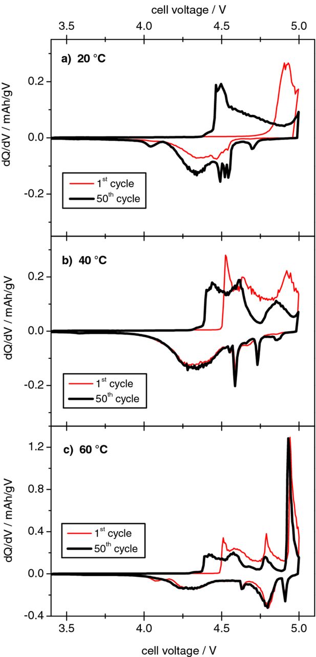
Figure 10. Differential capacity plots of the metallic lithium/KS6-graphite dual-ion cell during the 1st and 50th cycle of the constant current charge/discharge process at different temperatures, (a) 20°C, (b) 40°C, (c) 60°C (upper cut-off voltage: 5.0 V; current rate: 50 mA g−1).
It was proposed above that the anion intercalation being shifted to higher voltages at 20°C during the first charge is an indication for the presence of a kinetic effect. It is clear that at higher temperatures this kinetic effect diminishes. At 40°C and 60°C, the anion intercalation begins at a lower cell voltage of ca. 4.5 V, compared to 4.8 V at 20°C (Figure 9a–9c). Higher temperatures lead to an easier anion uptake in the graphite, which, in turn, results in higher discharge capacities. Furthermore, a strong decrease of the voltage hysteresis between the charge and discharge reactions is observed at elevated temperatures. The large hysteresis of ca. 0.4 V observed at 20°C is reduced to ca. 0.1 V at 60°C. Besides the above mentioned effects concerning the graphite/electrolyte interface ("opening" and wetting), an additional improvement could derive from the increased mobility of the TFSI− anions at elevated temperature. Table IV depicts a slight increase of the coulombic efficiency in the first and following cycles at higher temperatures. At 20°C the first cycle coulombic efficiency is ca. 72 % which increases to ca. 77 % at 40°C and 75 % at 60°C. However, in the 50th cycle, the coulombic efficiency decreases with increasing temperature; from 99.4 % (20°C) to 95.8 % (60°C). This decrease in efficiency is assumingly due to an increased self discharge reaction of the TFSI-graphite intercalation compound at higher temperatures.
Self-discharge investigations
Figure 11 summarizes the results of the self-discharge investigation for the Li/KS6 dual-ion cell at 20°C, 40°C and 60°C. The cell was charged to a cut-off voltage of 5.0 V. Then, the cell voltage change was determined after rest periods of 12 or 24 hours. At 20°C (Figure 11a), the cell voltage relaxed almost suddenly from 5.0 to 4.8 V. After 24 hours rest, it reached a constant plateau value of 4.68 V. The voltage change at 60°C (Figure 11b) is different. The cell voltage is decreasing in a continuous manner and the relaxation occurs slower, that a plateau value is not reached after 24 hours. The correlation of the discharge capacity and the coulombic efficiency with different rest times at 20°C, 40°C and 60°C is depicted in Figures 11c and 11d.
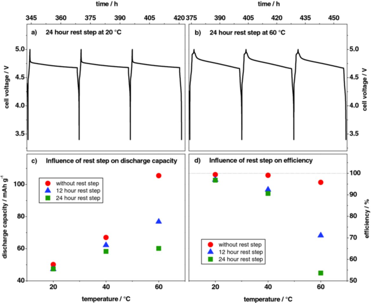
Figure 11. Self-discharge investigations with different rest periods after a constant current charge process (50 mA g−1) of the metallic lithium/KS6-graphite dual-ion cell performed at different temperatures; upper cut-off cell voltage: 5.0 V; (a) cell voltage profile with 24 hour rest time at 20°C, (b) cell voltage profile with 24 hour rest time at 60°C, (c) correlation between discharge capacity and rest step time at 20°C, 40°C and 60°C, (d) correlation between coulombic efficiency and rest step time at 20°C, 40°C and 60°C.
After both, 12 and 24 hours rest time at 20°C, the discharge capacity decreases from ca. 50 mAh g−1 to 47 mAh g−1, as in both cases, the plateau value is reached early during the storage experiment (Figure 11a). Elevated temperatures, however, lead to increased self‑discharge, e. g. at 60°C the discharge capacity decreases from 105 mAh g−1 to about 60 mAh g−1 after 24 h rest time. The discharge capacity is expected to further decrease with rest time, as no plateau value is reached after 24 h in the voltage profile (Figure 11b). This decrease in the discharge capacity after these storage experiments may explain the poorer charge/discharge cycling efficiencies at higher temperatures.
Self-discharge means that some chemical reactions inside the cell consume charge, which is then not available during discharge outside the cell.81 A chemical reaction inside the cell may be the oxidative decomposition of TFSI—anions inside the graphite positive. Another possible, but in our opinion less likely, side reaction is the reaction of the intercalated anions with electrode components, such as graphite, binder, conductive additive and current collector. Further investigations regarding the ionic liquid electrolyte stability have to be performed in order to exactly determine the origin of charge loss. In addition, a partial destruction of the graphite structure by the anion intercalation/de-intercalation reactions cannot completely be excluded. Nevertheless, the operation conditions for dual-ion cells are by far not as detrimental, with regard to the stability of the graphite structure, as compared to the synthesis conditions for expanded graphite or graphene oxide. The synthesis of expanded graphite typically includes the use of strongly oxidizing agents and/or high temperatures.82,83
Although the self-discharge is higher at elevated temperature, the discharge capacity of the cell can be retained by a constant voltage holding step at the investigated cut-off voltage. At a temperature of 20°C, a specific current of only 0.5 mA g−1 has to be applied to hold the cell at the cut-off voltage of 5.0 V. At 40°C and 60°C the current density needs to be increased to about 1 mA g−1 and 5 mA g−1, respectively. These current values correspond to approximately 1.3 % h−1 and 5 % h−1 self-discharge at 40°C and 60°C, respectively. These "floating charge" conditions may have an impact on the possible applications of the dual-ion systems.
Long-term charge/discharge cycling performance
Both dual-ion systems (Li/KS6 and LTO/KS6) provide a very stable charge/discharge cycling performance at a current of 50 mA g−1 over 500 charge/discharge cycles at 20°C (Figure 12a and 12b). The capacity retention after 500 cycles is higher than 99 % for both systems, with an average coulombic efficiency of 99.1 ± 0.8 % for the Li/KS6 dual-ion cell and 99.3 ± 0.9 % for the LTO/KS6 system. Furthermore, Figure 12c displays that this stable cycling performance can also be obtained at higher temperatures, namely at 40°C and 60°C. The capacity retention after 500 cycles for the Li/KS6 dual-ion cell at 40°C is about 97 % and ca. 93 % at 60°C; with average coulombic efficiencies of 98.2 ± 0.5 % at 40°C and 95.4 ± 0.9 % at 60°C.
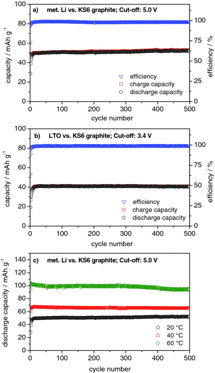
Figure 12. Constant current charge/discharge cycling curves and coulombic efficiencies for (a) the metallic lithium/KS6-graphite dual-ion cell (upper cut-off voltage: 5.0 V) and (b) the LTO/KS6-graphite dual-ion cell (upper cut-off voltage: 3.4 V); (c) Constant current discharge cycling curves for the metallic lithium/KS6-graphite dual-ion cell (upper cut-off voltage: 5.0 V) at 20°C, 40°C and 60°C. (Current density: 50 mA g−1).
Conclusions
In this work, we introduced two dual-ion cell energy storage systems taking advantage of anion intercalation into graphitic carbon cathodes. These systems are based on the intercalation of bis(trifluoromethanesulfonyl)imide anions into graphite the positive electrode from an ionic liquid-based electrolyte (LiTFSI-Pyr14TFSI). As anode either metallic lithium or lithium titanate Li4Ti5O12 were used, both displaying a good compatibility with the ionic liquid-based electrolyte.
The dependence of the discharge capacity and efficiency on the cut-off voltage was investigated. In general, it was observed that by increasing the cut-off voltage, the anion uptake and therefore the discharge capacity were increased. Nevertheless, the benefits from increasing the discharge capacity by increasing the voltage were limited, as exceeding a certain cell voltage led to a decrease in coulombic efficiency, most likely due to electrolyte decomposition reactions. Therefore, optimized upper cut-off voltages were determined, namely from 4.8 to 5.1 V for the metallic lithium based systems and from 3.2 to 3.6 V for the LTO based dual-ion cells. Within these high voltage cut-off limits, coulombic efficiencies of more than 99 % were achieved, indicating that electrolyte degradation is small. Rate performance investigations revealed that even at high discharge current rates large discharge capacities were obtained. Similar experiments with corresponding charge and discharge rates clearly indicated that the anion uptake ( = cell charge), and not their release, is the kinetically limiting factor for the current rate performance of these cells. In fact, applying a constant voltage step during charging resulted in a remarkably increase of the anion uptake capability of the graphite and therefore of the discharge capacity.
An increase in temperature resulted in an increased anion uptake and, consequently, elevated discharge capacities exceeding 100 mAh g−1 were achieved at 60°C. Voltage profiles obtained at elevated temperatures also indicated the presence of a kinetic effect hindering anion intercalation in the first charge/discharge cycle, which is very prominent at lower temperatures, but diminishes at higher temperatures.
Both dual-ion systems provided excellent charge/discharge cycling behavior when using upper cut-off voltages of 3.40 V for the LTO-based dual-ion cell and 5.00 V for the metallic lithium-based dual-ion cell. The capacity retention after 500 cycles exceeded 99 % for both systems. Even at 40°C and 60°C the anion uptake and release was very reversible, with a capacity retention of 97 % and 93 % for the metallic lithium based dual-ion cell after 500 cycles. However, a self-discharge process (5 % h−1) was observed at the highest temperature (60°C). It is clear that higher temperatures promote the kinetics of desired and undesired reactions of the dual-ion cell.
The advantages of the dual-ion system are certainly that the used solid materials are cheap, abundant and environmentally friendly. The ionic liquid electrolyte offers favorable properties such as non‑flammability, non-volatility and a very good compatibility with the lithium metal anode. On the other hand, as long as ionic liquids are not mass-produced, the costs of the electrolyte are significant.
In our previous communication,60 we calculated the maximum theoretical energy densities, that may be achieved with the dual-ion cells. We proposed, that the practical specific energy (Wh kg−1) may be in the range of ca. 80 % of the energy of a Li4Ti5O12/LiFePO4 cell (average discharge cell voltage of 1.9 V) with organic solvent-based electrolyte.60 This may be "enough" for a stationary battery, but is probably not sufficient for automotive applications. In particular, dual-ion cells may not only tolerate, but also need floating charge conditions, to keep the charged capacity and counteract self-discharge, which is another argument for use in stationary applications. The most probable self-discharge mechanism involves the degradation of intercalated anions.
Acknowledgments
The authors thank the German Ministry of Education and Research (BMBF) for funding of this work in the project "LiVe" (03×4601A) within the "LIB2015" research alliance. We gratefully acknowledge the supply of materials by TIMCAL (KS6 graphite and C‑nergy Super C65) and Chemetall (metallic lithium foil).