
Abstract
Li-In electrodes are widely applied as counter electrodes in fundamental research on Li-metal all-solid-state batteries. It is commonly assumed that the Li-In anode is not rate limiting, i.e. the measurement results are expected to be representative of the investigated electrode of interest. However, this assumption is rarely verified, and some counterexamples were recently demonstrated in literature. Herein, we fabricate Li-In anodes in three different ways and systematically evaluate the electrochemical properties in two- and three-electrode half-cells. The most common method of pressing Li and In metal sheets together during cell assembly resulted in poor homogeneity and low rate performance, which may result in data misinterpretation when applied for investigations on cathodic phenomena. The formation of a Li-poor region on the separator side of the anode is identified as a major kinetic bottleneck. An alternative fabrication of a Li-In powder anode resulted in no kinetic benefits. In contrast, preparing a composite from Li-In powder and sulfide electrolyte powder alleviated the kinetic limitation, resulted in superior rate performance, and minimized the impedance. The results emphasize the need to fabricate optimized Li-In anodes to ensure suitability as a counter electrode in solid-state cells.

Highlights
The fabrication of Li-In anodes needs to be optimized to ensure suitability as a counter electrode in sulfide all-solid-state batteries.
The Li-In counter electrode may often be the limiting factor of sulfide all-solid-state halfcells.
Pressing Li and In foil together results in a kinetically limited anode.
Composites from Li-In and sulfide electrolyte result in stable reference potential, superior rate performance and low impedance of the counter electrode.
Export citation and abstract BibTeX RIS

This is an open access article distributed under the terms of the Creative Commons Attribution 4.0 License (CC BY, http://creativecommons.org/licenses/by/4.0/), which permits unrestricted reuse of the work in any medium, provided the original work is properly cited.
Li-metal all-solid-state batteries (ASSBs) are widely regarded as a promising energy storage technology, most notably for applications in electric vehicles. 1,2 Especially ASSBs with sulfide (thiophosphate) solid electrolytes (SEs) are currently rising as the dominant cell concept, due to the high ionic conductivity of the sulfide SE. 3,4 However, the technological maturity of sulfide ASSBs is still low and the research gap between ASSBs and state-of-the-art Li-ion batteries with liquid electrolyte is still large. Many key ASSB challenges such as chemomechanical contact loss, 5–7 interphase formation 8,9 and transport kinetics 10,11 require deeper understanding. Currently, extensive lab-scale research and development is taking place, as shown by the ever-increasing number of papers published in the recent years. 12
Most commonly, individual ASSB fundamental research publications focus on the understanding of a single problem in a single ASSB component as part of a model cell. For studies on sulfide composite cathodes, commonly seen cell concepts consist of a composite cathode, sulfide separator and a metal anode as an additional Li reservoir. In a typical experiment, a two-electrode setup is employed, where the cathode (working electrode, WE) parameters, such as composition, mass loading and densification, are varied. The sulfide separator, and the anode (counter electrode, CE) are kept constant. Any recorded differences in the cell performance are then correlated with the varied cathode parameters. The WE potential of the cell is controlled against the CE potential. We refer to this cell concept as a half-cell, in analogy to half-cells with Li-metal CEs as commonly seen in literature on lithium-ion batteries with liquid electrolytes. 13 Due to the CE potential control, it is desirable that the anode has a defined reference potential and does not generate significant overpotentials during electrochemical characterization. Usually, in cathode studies it is assumed that the CE is well-performing and is not considered as a significant bottleneck or performance limiting factor of the cell. However, this assumption is rarely confirmed experimentally. Diffusive limitations in alloying anodes have been reported in literature. 14 Especially since composite cathodes have been steadily improving over the last years, it is important to verify that the model cell anodes can keep up with the cathode performance and ensure that any recorded data from the model half-cells can be correctly attributed to cathode effects. 15,16 The most straightforward way to differentiate between cathode and anode effects in the same cell is a three-electrode cell setup. However, implementing a separate reference electrode (RE) into a solid-state cell is technically challenging and therefore literature on this topic is still scarce. 17–21
Several materials are suitable as CEs for cathode studies. Li metal, despite having a constant potential and being desirable for practical application, is rarely seen as a counter electrode in cathode research, owing to its high reactivity towards sulfide SEs 22 and tendency towards dendrite growth. 23,24 A common strategy to reduce SE decomposition at the anode interface and suppress dendrite growth is to employ a Li alloy anode with metals such as In, Al, Sn, and Mg. 25 Especially the Li-In system is highly popular for sulfide ASSB research, due to the high ductility of In and ease of alloying under pressure at room temperature, which enables easy cell assembly in laboratories, as well as a stable reference potential of 0.62 V vs Li+/Li in a broad stoichiometric region. 26
The Li-In binary system possesses several LixIny intermetallic phases with  The
The  region is featureless, where just the equimolar LiIn phase and the pure In phase coexist.
27
In this work, we designate the alloy with unspecified stoichiometry as Li-In to differentiate from the specific equimolar phase LiIn. Santhosha et al. conducted coulometric titration of Li-In electrodes and concluded that indeed the In+LiIn two-phase region is responsible for the well-known reference potential of 0.62 V vs Li+/Li.
26
The Li-richer phases show lower potentials, which are strongly dependent on small lithiation changes.
26
Wang et al. showed that a low Li content in the Li-In anode of ASSBs is also beneficial for the reversibility and capacity of the cell.
28
Nam et al. critically evaluated the rate capability of the Li-In anode in a test cell with a Sn WE and showed that the preparation method of the alloy is critical to ensure fast kinetics. They supported their claims with three-electrode studies on the Li-In/Sn cell.
20
Very recently, Sedlmeier et al. demonstrated that spatial inhomogeneities of the Li-In alloy may lead to poor electrode performance. They employed three-electrode impedance measurements to identify the importance of sufficient Li concentration near the separator.
21
Ikezawa et al. used a three-electrode cell to demonstrate that the Li-In anode in a Li-In/LCO can become a performance bottleneck at rates above 1 C.
16
region is featureless, where just the equimolar LiIn phase and the pure In phase coexist.
27
In this work, we designate the alloy with unspecified stoichiometry as Li-In to differentiate from the specific equimolar phase LiIn. Santhosha et al. conducted coulometric titration of Li-In electrodes and concluded that indeed the In+LiIn two-phase region is responsible for the well-known reference potential of 0.62 V vs Li+/Li.
26
The Li-richer phases show lower potentials, which are strongly dependent on small lithiation changes.
26
Wang et al. showed that a low Li content in the Li-In anode of ASSBs is also beneficial for the reversibility and capacity of the cell.
28
Nam et al. critically evaluated the rate capability of the Li-In anode in a test cell with a Sn WE and showed that the preparation method of the alloy is critical to ensure fast kinetics. They supported their claims with three-electrode studies on the Li-In/Sn cell.
20
Very recently, Sedlmeier et al. demonstrated that spatial inhomogeneities of the Li-In alloy may lead to poor electrode performance. They employed three-electrode impedance measurements to identify the importance of sufficient Li concentration near the separator.
21
Ikezawa et al. used a three-electrode cell to demonstrate that the Li-In anode in a Li-In/LCO can become a performance bottleneck at rates above 1 C.
16
In this work, we critically evaluate the suitability of Li-In as a counter electrode in two electrode half-cell assemblies of sulfide-based ASSBs. We fabricate the Li-In electrode with three different methods and study the voltage profiles, rate performance and impedance spectra of Li-In/NCM ASSBs in two- and three-electrode configurations. We use the chronoamperometry method to show that kinetic bottlenecks in the Li-In CE can easily become performance-limiting in ASSBs with optimized composite cathodes and suggest improved fabrication protocols to ensure optimal Li-In performance.
Experimental
Li6PS5Cl (LPSCl, NEI Corp.) was used as the SE. Single crystal LiNi0.8Co0.1Mn0.1O2 (NCM811, MSE Supplies) was used as cathode active material (CAM). Vapor-grown carbon nanofibers (VGCF, Merck) were used as conductive additive. Metallic Li was supplied by Tobmachine. Indium foil was supplied by ChemPur. Indium powder was supplied by Merck. All material handling was performed in an Ar-filled glove box (<1 ppm O2, <1 ppm H2O).
Cathode composites were prepared by mixing CAM, SE and VGCF in a ball mill (Pulverisette 23, Fritsch) at mass ratios of 73.2%, 24.0% and 2.8%, respectively.
LiIn powder was prepared by rolling In and Li metal sheets (molar ratio 1:1) together by hand between a steel tube and a steel plate. The alloy was rolled and folded together repeatedly until it became dark and brittle. Electron microscopy images of the equimolar LiIn alloy can be seen in Fig. S1. Afterwards, it was transferred to an agate mortar and mixed with excess indium powder to produce Li-In powder with Li molar ratio of 36 at%, 40 at%, 44 at% and 47 at%.
Li-In-SE composites were prepared by adding SE with mass ratios of 20% or 40% to Li-In powder (40 at% Li). The mixture was mortared until a homogenous grey power was achieved.
Two-electrode ASSB half-cells were assembled in an electrochemical cell with 10 mm diameter consisting of a PET mold and two stainless steel pistons (Type KP, Hohsen Corp.). First, 150 mg of LPSCl was uniaxially pressed at 500 MPa, forming a separator pellet. Then, the anode was attached on the separator pellet by either a) stacking In (75 mg, 125 μm thickness, 10 mm diameter), then Li (3.6–4.4 mg, 80–100 μm thickness, 10 mm diameter) on the separator and uniaxially pressing at 500 MPa for 1 min, or b) adding 80 mg LiIn powder on the separator and uniaxially pressing at 500 MPa for 1 min, or c) adding 80 mg Li-In-SE composite powder on the separator and uniaxially pressing at 500 MPa for 1 min. Afterwards, 15 mg of the composite cathode (nominal load of 2.80 mAh cm−2) was added on the other side of the pellet, and uniaxially pressed at 500 MPa for 1 min. Three-electrode ASSB half-cells were assembled in an electrochemical cell with 12 mm diameter consisting of a PEEK mold and two WC pistons (CompreCell 12PEEK-DP, rhd instruments). A 400 μm thick, straightened copper wire was placed inside the PEEK mold. Then, 216 mg of LPSCl was uniaxially pressed at 375 MPa, forming a separator pellet with a copper wire roughly through the middle. Then, the anode was attached on the separator pellet by either a) stacking In (108 mg, 12 mm diameter), then Li (4.4 mg, 12 mm diameter) on the separator and uniaxially pressing at 500 MPa for 1 min, or b) adding 120 mg Li-In-SE composite powder on the separator and uniaxially pressing at 500 MPa for 1 min. Afterwards, 21.6 mg of the composite cathode (nominal load of 2.80 mAh cm−2) was added on the other side of the pellet, and uniaxially pressed at 500 MPa for 1 min. Before electrochemical testing, the copper wire was in situ plated with Li with 110 μA cm−2 for 15 h, forming a Li RE. A schematic of the two- and three-electrode cells is shown in Fig. S2.
The two-electrode ASSBs were characterized at 30 °C using a Biologic VMP-3e potentiostat and a stack pressure of ca. 50 MPa. The three-electrode ASSBs were characterized in a CompreDrive cell stand (rhd Instruments) with a Biologic VSP potentiostat at room temperature and a stack pressure of 50 MPa. For the three electrode cells, the WE potential was controlled against the CE potential to reproduce the two-electrode cell experiments. CE and WE potentials were additionally monitored against the RE. The cell voltage was 2.38–3.68 V vs Li+/LiIn (3.00–4.30 V vs Li+/Li). 26 C-Rates were calculated based on the nominal capacity of the CAM. The measurement protocol consisted of an initial 4 h relaxation, followed by two formation cycles at 0.1 C with constant-current constant-voltage (CCCV) charging and constant-current (CC) discharging, with 10-min relaxation steps after each charge and discharge. The charging limiting current was set to 0.02 C. The cells are charged according to the same CCCV protocol and chronoamperometric discharge step (3.0 V vs Li+/Li) was performed as a rate performance test 29 with a current of 0.02 C as termination criterion for a total of three cycles. Afterwards, the cells were charged with 0.1 C up to half of the experimental capacity, which resulted in a cell voltage of ∼3.2 V. The cell was relaxed for 5 h and an impedance spectrum was recorded in the 1 MHz—10 mHz (two-electrode) or 1 MHz—100 mHz (three-electrode) range with an excitation amplitude of 25 mV.
Results and Discussion
In the following, we compare Li-In/NCM811 cells with the same cathode composition and varied anode type and lithium content (Fig. 1. At first, we employed the by far most common fabrication method of the Li-In anode (CE). A in situ mechanochemical reaction of Li and In was forced by pressing the two metal foils together within the assembled cell. The initial charge and discharge curves of these cells (Fig. 1a) are nearly identical for lithium contents of 45, 47 and 49 at% and show the typical voltage profile of NCM811, suggesting that the CE potential is likely stable at 0.62 V. It is assumed that the anode is within the two-phase In+LiIn region and no Li-rich phases are yet present. 26 At 50% Li a significant change in the voltage profile as well as much lower charge and discharge capacities are observed. It is noteworthy that the charging curves initially overlap and then deviate as soon as ca. 50 mAh g−1 are charged. In the two-electrode configuration, the potential is referenced to the Li-In CE, only. Overlithiation of Li-In likely occurs due to the high initial Li content of the anode and the additional Li that is introduced into the anode during charging. This leads to the generation of Li-rich phases such as Li5In4 or Li3In2, 26,27 which lower the anode and reference potential below the target 0.62 V. A potential shift of roughly 0.2 V is observed at comparable charging capacities. This is roughly consistent with the Li5In4 potential as observed by Santhosha et al. 26 Consequently, the upper charging limit of the cell is achieved before the CAM is completely delithiated. In other words, the ASSB is effectively cycled to a lower cut-off potential of roughly 4.1 V relative to Li/Li+and thus significantly lower than the 4.3 V vs Li/Li+ as intended in the experiment. Therefore, the CAM does not get fully charged, leading to lower capacity. The first cycle coulombic efficiencies are given in Table S1 and show a decreasing trend with increasing Li content, which might be an indication of increased SE degradation at the interface of Li rich anodes and the SE. Figure 1d compares the rate performance of the same cells with metal foil-based anodes. We employed the constant-voltage chronoamperometric method during discharge (anode delithiation), which was explained elsewhere. 29,30 We note that the rate performance curves are recorded from high (right) to low (left) C-rates i.e., the cell initially experiences its highest possible discharge rate, and then discharges to completion with a steadily decreasing rate. The anodes with high Lithium content (49% and 50%) demonstrate superior rate performance and stability during the high-rate test. The shape of the chronoamperometry profiles shows a low-rate plateau and a steep rate performance drop, which is typical for cathode-limited cells. 29–31 When the Lithium content is decreased to 47%, the available capacity at high rates (>2 C) decreases strongly, but is slightly higher at low rates. In addition, there is a notable shift in the high-rate performance between the first and second measurement, indicating rapid degradation. At a lithium content of 45%, the rate performance worsens further, and the degradation effects become more severe. Figure 1g shows the impedance spectra recorded at 3.2 V which represents ca. 50% state of charge of the CAM ASSBs with anodes with higher lithium content show a single semicircle in the high frequency region (ca. 1 kHz), whereas anodes with lower Li content show a high frequency contribution and an additional semicircle in the low frequency region (1–10 Hz). Prior impedance studies on sulfide ASSBs have established that higher frequencies are associated with cathode effects and lower frequencies are associated with anode effects. 32,33 It is therefore very likely that the observed performance loss for Li-In anodes with low Li content is related to the emergence of the additional impedance at the anode side. We note that the low frequency semicircle is notably larger for the Li-poorest anode. The variation in the high frequency impedance is most likely not related to the anode and is within the typical error of the measurement, considering that the charge transfer resistance of composite cathodes is very sensitive to the state of charge. 34 Detailed quantitative analyses and modelling of the impedance spectra are beyond the scope of this study.

Figure 1. (a)–(c): Charge and discharge curves of the initial two CCCV cycles of Li-In/NCM811 ASSBs with various Li-In anode types and Li content. (d)–(f): Discharge rate performance of the ASSBs recorded via chronoamperometry (three cycles). (g)–(i): Impedance spectra of the ASSBs at 3.2 V vs Li-In, corresponding to ca. 50% SOC.
Download figure:
Standard image High-resolution imageOverall, the data indicates that the rate capability bottleneck of the ASSBs shifts from the cathode side to the anode side as the lithium content of the anode is decreased. However, increasing the lithium content too much presumably leads to the generation of undesirable Li-rich LixIny phases, which changes the anode's potential, and therefore hinders its usefulness as a stable RE/CE for cathode characterization. Overall, there appears to be a narrow sweet spot at around 49 at% Li content of the metal foil anode where both sufficiently high rate performance and stable anode potential are present.
As an alternative to the one-time uniaxial pressing of metal foils on top the separator pellet, the LiIn anode phase was pre-mixed and prepared as a powder in different Li-In ratios. The resulting Li-In powder was used as anode material by pressing it onto a separator pellet. Charge and discharge curves of the ASSBs with powder anodes at increasing Li content are shown in Fig. 1b. Similarly to the metal foil anodes, typical Li-In/NCM811 profiles are present at lower Li contents (36 at% and 40 at%), and a shift in the potential is observed for higher Li contents (44% and 47%). The latter cells also show lower charge and discharge capacities due to the drop in anode potential while cycling as described above. It is notable that this effect already occurs for lower Li contents as compared to the metal foil anodes (cf Fig. 1a). Presumably the thorough pre-mixing of the anode results in a more quantitative reaction between Li and In and therefore a more homogenous Li distribution in the alloy. The first cycle coulombic efficiencies decrease with increasing Li content (Table S1), similar to the foil anodes. Figure 1e shows the rate performance of the Li-In powder anodes. A stable and sufficiently high-rate performance is only seen for the highest Li content at 47 at%. All cells with lower Li content show severe rate limitations. The impedance measurements of the corresponding cells (Fig. 1f) show a similar trend to the cells with LiIn metal anodes. Lower Li content in the anode is again associated with the emergence of a significant additional impedance in the low frequency region. An absence of a second semicircle is seen only for the highest Li content. Overall, the Li-In powder anodes show either sufficient capacity and very poor rate performance, or optimal rate performance at the cost of utilizable capacity. An optimal compromise with simultaneously high rate performance and capacity could not be achieved.
The final studied anode comprises a composite of Li-In powder with fixed Li content of 40 at% and 20 wt% or 40 wt% sulfide electrolyte powder as suggested by Nam et al. 20 The respective voltage profiles and rate performance plots are given in Figs. 1c and 1f. Typical Li-In vs NCM811 profiles are clearly observed for the initial cycles, as well as superior rate performance and stability, despite the comparatively low amount of lithium in the anode. The first cycle coulombic efficiency (Table S1) is higher for the anode composite with 40% sulfide. The corresponding impedance spectra only show a single semicircle (Fig. 1i) with no notable resistive contributions at low frequencies. Thus, the best and most stable performance in this study is achieved with the anode composite with 40% sulfide.
The electrochemical cycling data clearly shows that preparing a well-performing Li-In CE is not trivial, as relatively small changes in the lithium content and the method of preparation have a massive impact on the ASSB characterization, especially at high rates. The nature of the rate performance failure suggests a kinetic limitation of Li transport in the alloy and/or across the anode-separator interface during anode delithiation (cell discharge). A previous study by Nam et al. 20 demonstrated that Li-depleted In-rich layers with low Li conductivity are formed during delithiation of the LiIn alloy. Effectively, only the LiIn species in close proximity to the SE layer undergo delithiation and further Li transport from the bulk of the anode is very slow. Therefore, only a small portion of the alloy anode is utilized as a reversible Li reservoir. Formation of Li depletion layers in separator proximity is a likely explanation for the rate performance limitations observed in this study. Li depletion would also explain the observed additional anodic impedance in the Li poor cells. This is also supported by the observation that increasing the Li content of the alloy tends to improve Li transport kinetics and cell performance, as well as reduce the anodic impedance. This result is contrary to the findings of Wang et al., who identified Li content as low as 14.3 at% as optimal and claimed that the Li-ion diffusion in In is quick enough is to facilitate fast kinetics. 28 We suspect that methodic differences could explain the differing findings, since our study was done with considerably higher rates and lower stack and assembly pressure. Increasing Li content to promote kinetics is however not an ideal approach since a very high Li content is necessary to ensure sufficient rate performance, therefore there is a large risk of overlithiating the anode and deviating from the target In+LiIn potential. Moreover, the excess Li delivered by the CAM in the first charge must be additionally accommodated in the Li-rich anode without causing a potential drop. We note that for the cells with metal foils, steps of about 2 at% Li had a significant impact on the rate capability and voltage profile of the ASSBs (Figs. 1a, 1d), which correspond to gravimetric differences of just 0.2–0.3 mg Li during the manual cell fabrication. Adjusting the optimal Li to In ratio in a reproducible way using metal foils may therefore be challenging.
A further experimental difficulty is achieving a spatially homogenous alloy using uniaxial pressing alone. Figure 2 shows photographs of a Li-In foil-type anode, manufactured by uniaxially pressing Li and In foil with 40 at% Li at a high pressure of 500 MPa. It appears that the dark colored Li-In phases are found mostly on the Li side of the disc, while the In side of the disc consists mostly of metallic In with only minor Li-In regions, implying an incomplete intermetallic reaction. In an ASSB stack the In side is in contact to the separator while the Li side is directed to the current collector piston. We therefore expect the existence of an In-rich layer in immediate proximity to the separator to aggravate the Li transport limitations during fast delithiiation. We note that for the alloys shown in Fig. 2 we pressed discs of 10 mm diameter in a 13 mm die, and it appears that the Li-In phases remained at roughly the initial 10 mm, while the In phase was flattened to 13 mm. It is crucial that while Li and In are both soft metals, the LiIn intermetallic phase is a crystalline Zintl-phase with significant ionic bonding character. 35 Perhaps unintuitively, Li-In does not flow plastically and does not distribute evenly in the soft indium matrix with uniaxial pressing alone, even at high fabrication pressures of 500 MPa. 21 Effectively, most of the generated Li-In phases remain embedded on the current collector side of the In foil and do not reach the separator side in order to function as a utilizable lithium reservoir. We also note that many ASSB studies are performed with Li-In anodes fabricated from lithium and indium discs of different diameters, where the diameter is used to control the Li to In ratio rather than the foil thickness. We recommend against using different diameters of Li and In due to the demonstrated poor flowability of the Li-In alloy, which could to lead to additional lateral inhomogeneity of the anode during fabrication and uneven current distribution during electrochemical testing.
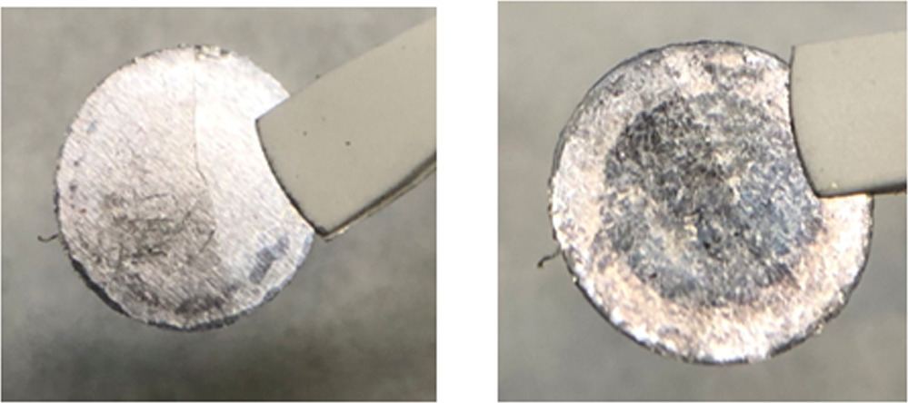
Figure 2. Photographs of a unaxially pressed Li-In foil-type anode. Left: Indium side. Right: Lithium side.
Download figure:
Standard image High-resolution imageSedlmeier et al. attempted to use the alloy inhomogenity to their advantage by turning the Li side to the separator and the In side to the current collector. 21 While this approach was shown to increase the size of the accessible Li reservoir, it has the drawback of significantly increasing degradation due to the poor interfacial stability between Li and the SE and was therefore not used in this work.
The Li-In powder anodes are expected to contain more of the LiIn Phase, corresponding to a more complete reaction between Li and In. Figure S1 shows electron microscopy images of the equimolar LiIn powder alloy. The powder consists of mostly rough particles with sizes 20–100 μm. Microscopic inhomogeneites exist, as shown by ca. 1 μm large In-rich domains (light colors in Fig. S1), due to the incomplete mechanic alloying via low-energy manual mixing. However, the homogeniety is still considered significantly higher than the Li-In foil, therefore it is assumed that the powder type anode can provide a Li reservoir in close proximity to the separator. Despite this, no anode composition with optimal performance could be fabricated, in contrast to the Li-In metal anodes. The data suggests that the Li depletion issue during fast discharge persists, which indicates that the Li depletion is primarily a function of the contact surface between the SE and LiIn.
It is possible that additional contacting difficulties are present when pressing the hard Li-In particles into the pre-pressed separator pellet. In contrast, pressing a sheet of soft indium as part of a Li-In foil anode has the advantage of creating intimate separator-anode contacts due to the flowability of In. The Li-In powder route also has the inevitable disadvantage of increased side reactions of Li with trace amounts of oxygen and water in the glove box during preparation due to the increased surface area of the powder. However, the major advantage of Li-In powder is that it can be mixed with the soft sulfide powder to produce a high performance well-percolated composite anode with high effective contact area to the separator. This approach was suggested by Nam et al. 20 and was verified in our study. We used lower Li content at 40 at% to guarantee that the anode potential stays within the In+LiIn two-phase region and still observed superior performance to all studied Li-In foil and Li-In powder anodes. By increasing the sulfide content from 20 wt% to 40 wt% a further slight performance increase is observed, which confirms that the effective ionic conductivity of the Li-In anode plays an important role in the overall discharge kinetics and may even be the kinetic bottleneck of typical ASSB half-cells with well-performing cathodes. The major differences of the studied anode compositions are summarized in Fig. 3.

Figure 3. Schematic of ASSBs with differing Li-In anode types and Li depletion during fast discharge conditions. The target LiIn phase is shown in purple.
Download figure:
Standard image High-resolution imageTo further separate the cathode and anode limitations of the cell performance, Li-In/NCM811 cells were built in a three-electrode configuration with a NCM811 WE, Li-In CE and Li RE. During electrochemical testing, the potential was controlled against the Li-In CE (as would be typical in a two electrode cell) and the Li RE was used purely to differentiate between cathodic and anodic overpotentials during cycling, as well as recording separate anodic and cathodic EIS spectra. In the following we compare two ASSBs with Li-In metal anode and Li-In-SE composite anode with 40% SE content. In both cases, the Li content of the Li-In phase is fixed at 40 at%. Figures 4a and 4b present galvanostatic cycling and chronoamperometry data, respectively.
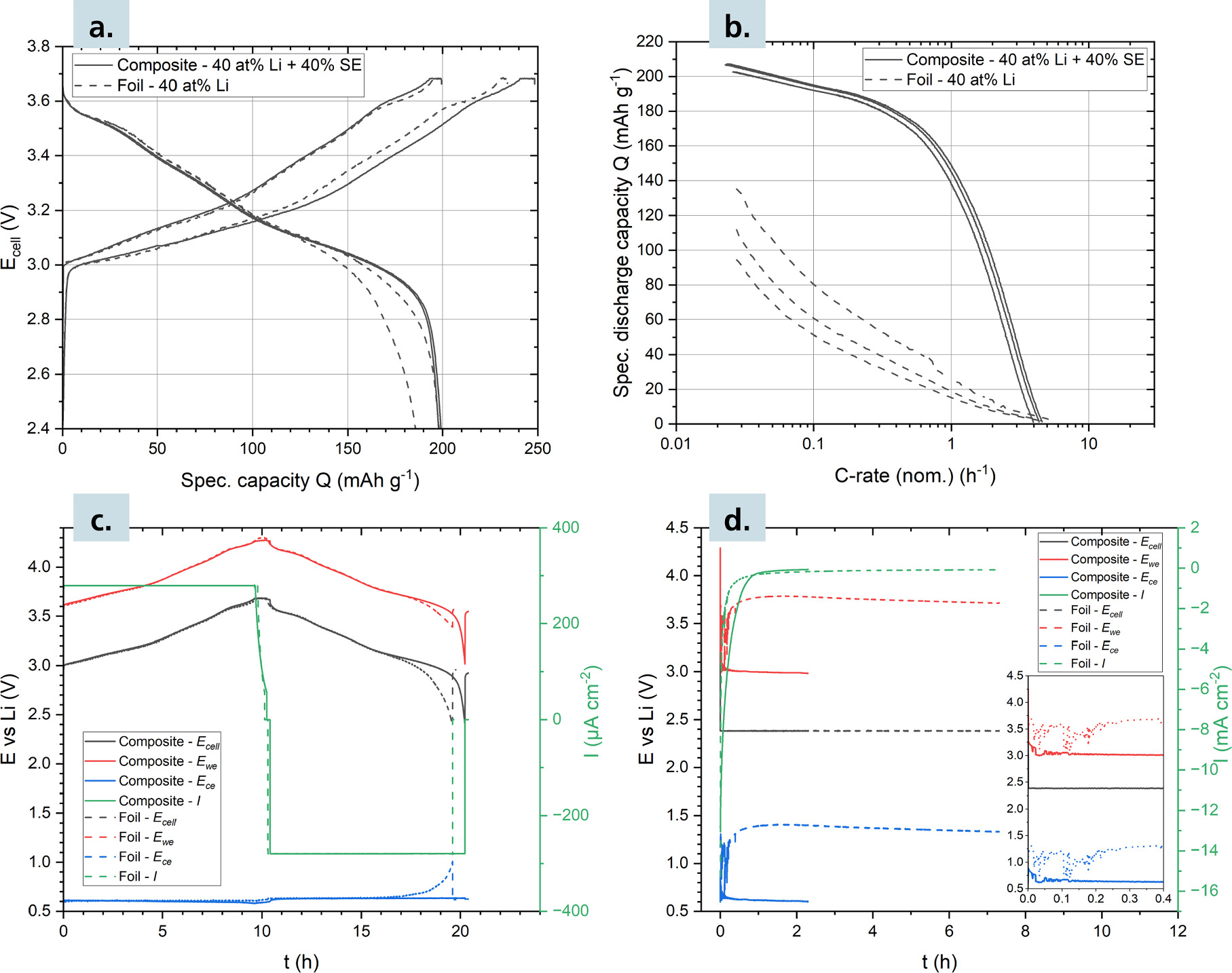
Figure 4. (a) Charge and discharge curves of the initial two CCCV cycles of Li-In/NCM811 three-electrode ASSBs with Li reference electrode and foil- and composite-type anode. (b): Discharge rate performance of the three-electrode ASSBs recorded via chronoamperometry (three cycles). (c): Time dependence of the WE, CE and cell potential and current density during the second CCCV cycle. (d): Time dependence of the WE, CE and cell potential and current density during the first chronoamperometric discharge.
Download figure:
Standard image High-resolution imageThe cell with Li-In metal loses capacity between the first and second galvanostatic cycle and shows severely limited performance during the rate capability test. In contrast, the Li-In-SE composite cell performs optimally during electrochemical testing. Figure 4c presents the time dependence of the working potential  counter potential
  and the cell potential
  during galvanostatic cycling. During charging (anode lithiation),
  remains constant at 0.61 V for both anode types, which translates to a minor anodic overpotential of about 10 mV considering the expected potential of 0.62 V. During discharge (delithiation)
  of both anode types are initially constant at ca. 0.63 V. However, at the end of discharging,
  of the Li-In metal cell significantly increases, whereas
  of the Li-In-SE composite cell remains constant. The increase of
  lowers
  which leads to an early termination of the discharge, and an overall reduced discharge capacity for the Li-In metal cell. These effects are exaggerated during electrochemical testing at high rates. Figure 4d shows the time dependence of the potentials during the first chronoamperometric discharge rate test. At the beginning of discharge, which corresponds to the highest current densities, the Li-In metal
  is very unstable and oscillates rapidly between 1.3 V and 0.7 V. After about 0.2 h,
  stabilizes between 1.4 V and 1.3 V vs Li+/Li until low-rate discharge completion, which corresponds to a very high anodic overpotential of over 0.7 V. Since the WE is referenced against the CE,
  is between 3.7 V and 3.8 V vs Li+/Li at discharge completion, instead of the ideal 3.0 V vs Li+/Li, explaining the uncomplete discharge. In contrast,
  of the Li-In-SE composite cell shows a much lower potential of ca. 0.9 V at the beginning of discharge and relaxes rapidly to 0.64 V at 0.2 h, which corresponds to an overpotential of just ca. 20 mV. Consequently,
  is correctly referenced at 3.0 V vs Li+/Li at discharge completion and the cathode is fully discharged. The three-electrode cycling data clearly indicates that the anode is responsible for the reduced capacity and rate capability differences of the studied cells. The observed overpotentials of the Li-In metal anode likely arise due to the ion-blocking properties of the In-rich Li-depletion layer generated during delithiation. The overpotentials are large enough to drastically influence the result of the measurement. These results are consistent with the results of Ikezawa et al., who demonstrated similar Li-In overpotentials in ASSBs at rates of 1 C.
16
In contrast, the Li-In-SE anode shows much lower overpotentials, which eventually relax to the expected In+LiIn potential even during chronoamperometric discharge and therefore do not significantly limit the rate performance and discharge capacity of the cathode.
is correctly referenced at 3.0 V vs Li+/Li at discharge completion and the cathode is fully discharged. The three-electrode cycling data clearly indicates that the anode is responsible for the reduced capacity and rate capability differences of the studied cells. The observed overpotentials of the Li-In metal anode likely arise due to the ion-blocking properties of the In-rich Li-depletion layer generated during delithiation. The overpotentials are large enough to drastically influence the result of the measurement. These results are consistent with the results of Ikezawa et al., who demonstrated similar Li-In overpotentials in ASSBs at rates of 1 C.
16
In contrast, the Li-In-SE anode shows much lower overpotentials, which eventually relax to the expected In+LiIn potential even during chronoamperometric discharge and therefore do not significantly limit the rate performance and discharge capacity of the cathode.
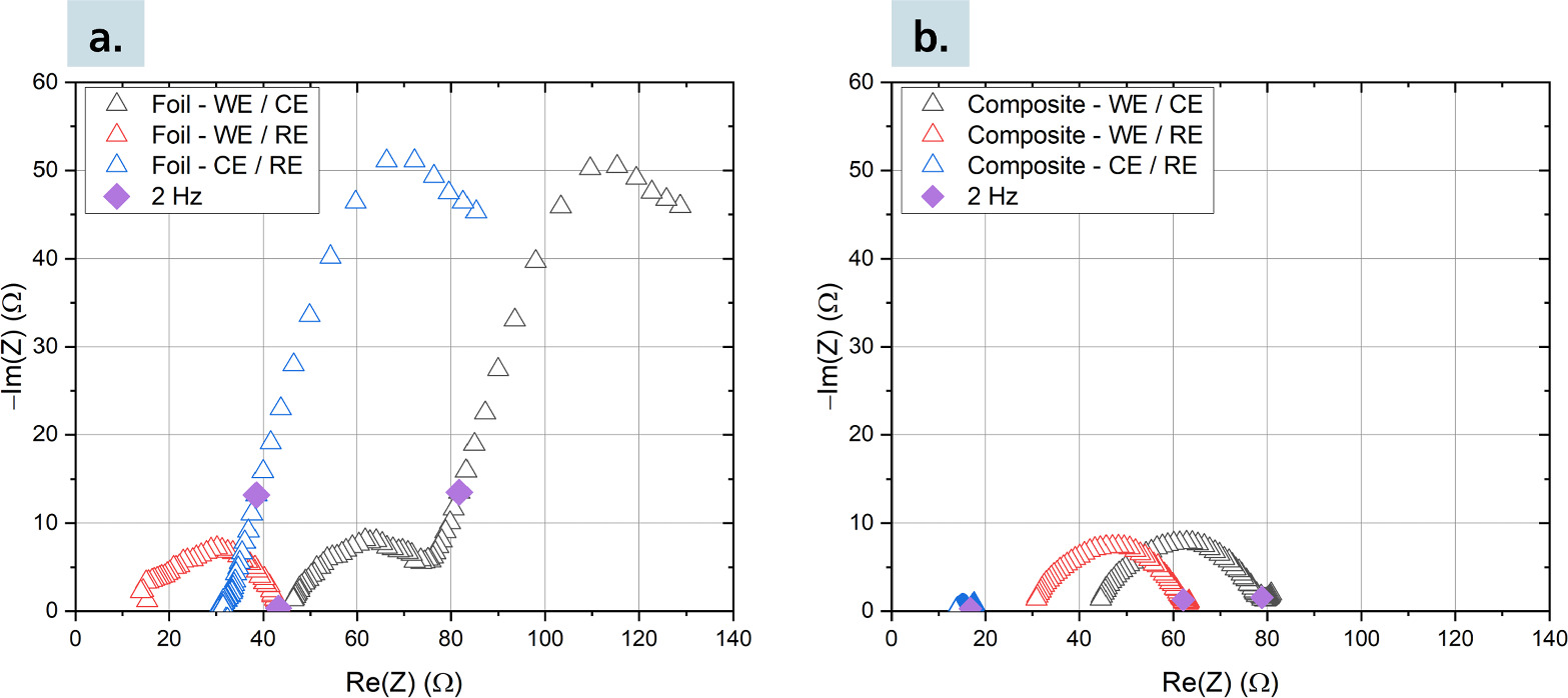
Figure 5 shows EIS spectra of the studied three-electrode cells. The EIS of the cell with Li-ln metal anode (Fig. 5a) shows a semicircle-like contribution of the cathode WE, which is typical and consistent with previous studies. 32 The Li-In CE contributes a very large impedance in the low frequency region. Between 10 Hz and 0.3 Hz predominantly blocking behavior is observed as the imaginary component of the impedance increases, and at very low frequencies >0.3 Hz additional resistance is observed. These impedance contributions likely describe the formation of an In-rich depletion layer and the sluggish Li+-ion transport through it, respectively. In contrast, the cell with Li-In-SE composite (Fig. 5b) shows purely resistive and overall insignificant CE contribution to the impedance spectrum. The obtained three-electrode impedance data is consistent with the generation of In-rich Li-depletion layers when using Li-In metal anodes, and their limiting nature at high current densities.
Figure 5. Impedance spectra at a cell voltage of 3.2 V of the three-electrode Li-In/NCM811 cells with (a) foil and (b) composite-type anode.
Download figure:
Standard image High-resolution image
Conclusions
The Li-In alloy is widely used as a counter electrode in two-electrode half-cells in cathode studies of sulfide-based ASSB. To be suitable as a counter electrode, the Li-In alloy anode must provide both a stable potential to ensure correct referencing of the working electrode potential, and sufficient rate performance at a low overpotential to ensure non-limiting behavior during battery testing. We show that the method of preparation of the Li-In alloy is of critical importance for the performance of the cell and its influence on the recorded data. Improper preparation can lead to a significant anode contribution on impedance spectra, rate performance tests and wrong referencing of the effective cathode potential.
Li-In foil-type anodes, which are used in the vast majority of sulfide ASSB works, showed severe kinetic limitations during rate performance testing. The collected data at high rates (in our case already ≪ 1 C = 2.80 mA cm−2) is strongly dominated by the anode, making it impossible to observe the cathode behavior. Impedance data shows a strong contribution of the anode as well. By increasing the lithium content in the Li-In alloy the anodic limitation decreases, nevertheless improper balancing can lead to the generation of undesirable Li-rich LixIny phases during charging, which effectively reduce the cut-off voltage relative to Li/Li+ by at least 0.2 V and thus terminates the charging at a low WE potential. Overall, it appears that there is only a narrow sweet spot at around 49 at% Li content of the metal foil anode where the anode is not kinetically limiting at high rates and a stable anode potential is present. This sweet spot furthermore will be very susceptible to the preparation process by mechanical alloying under pressure. It is thus important for every laboratory using the metal foil approach to verify that their anode is not the kinetic bottleneck of a half cell, especially if working with optimized, highly loaded cathodes. Insufficient reproducibility, which is hardly reported in ASSB half-cell studies, at moderate C-rates can be easily explained by anode dominated data. Likewise, the deconvolution of half-cell impedance spectra e.g., when characterizing cathodic charge transfer phenomena, could be severely complicated by overlapping anode impedance.
We furthermore compare these results to Li-In powder-type anodes that are less susceptible to the cell preparation protocol, but they still show a similar, unfavorable compromise between stable potential and high-rate performance. Cycling and impedance data also imply the formation of a significant Li-poor region within the anode which severely limits the Li+ transport kinetics in the half cell. On the contrary, the Li-In-SE composite anode shows both a stable potential and a high rate performance due to negligible impedance contribution from the anode, allowing unambiguous interpretation of the collected data as cathode related. This approach is robust against compositional changes and works well at sufficiently low Li contents of about 40 at% Li (relative to the Li-In composition). It thus maintains enough storing capacity for lithium during initial charging avoiding the formation of Li-rich phases and the associated shift in potential. We strongly recommend the preparation of Li-In-SE composite anodes to ensure sufficient electrochemical performance and prevent the possibility of misinterpretation of anodic effects as cathodic effects in typical half cells. We believe that the methods and principles applied in this study can accelerate ASSB research and improve the significance, informative value, and reproducibility of collected electrochemical data.
Acknowledgments
This work is part of the projects "MaLiFest" (11–76251–99–2/17 (ZN3402)), which is funded by the Lower Saxony Ministry of Science and Culture, and "FB2-Oxid" (03XP0434B), which is funded by the German Federal Ministry of Education and Research.
Supplementary data (0.5 MB PDF)