
Abstract
Redox flow batteries (RFBs) are ideal for large-scale, long-duration energy storage applications. However, the limited solubility of most ions and compounds in aqueous and non-aqueous solvents (1M–1.5 M) restricts their use in the days-energy storage scenario, which necessitates a large volume of solution in the numerous tanks and the vast floorspace for these tanks, making the RFB systems costly. To resolve the low energy storage density issue, this work presents a novel way in which the reactants and products are stored in both solid and soluble forms and only the liquid with soluble ions is circulated through the batteries. Storing the active ions in solid form can greatly increase the storage energy density of the system. With a solid to liquid storage ratio of 2:1, for example, the energy density of the electrolyte of vanadium sulfate (VOSO4), an active compound used in the all-vanadium RFB, can be increased from 40 Ah l−1 to 163 Ah l−1 (>4X), allowing an existing 6-h RFB system to become a 24-h system with minimal modifications. To show how the concept works, an H2-V flow battery with a solid/liquid storage system is used, and its successful demonstration validates the solid-liquid storage concept.
Highlights
The hybrid system stores reactants as soluble ions and undissolved solid.
Only aqueous solution is circulated through the flow battery.
The storage system enables the day-length storage with existing storage facilities.
The dissolution/precipitation mechanism of V(IV) sulphate was investigated.
A H2-V flow battery with the hybrid storage system was demonstrated.
Energy generated from fossil fuels is being replaced with renewable/sustainable sources to combat global warming, and this can have a huge beneficial environmental impact worldwide because electricity accounts for more than a third of overall energy use. Wind/solar-generated electricity is already cost-competitive with carbon-based electricity in certain regions and markets. 1 Deploying these sustainable but intermittent energy sources beyond 20% is either not possible or not cost-effective without the availability of inexpensive energy storage solutions because (1) electricity distribution and usage networks cannot handle large variations and (2) excess electricity capacity generated during times of low demand is not utilized and does not bring economic benefit to the owners. For the large-scale application of intermittent energies, the energy storage capacity to handle the daily fluctuations is not sufficient. To deal with the unpredictable long-term non-availability, a longer duration storage capacity is needed.
Storage systems based on redox flow batteries (RFBs) made of power generation units and separate external storage units enable versatile power and energy designs, which are well suited for the large-scale, long-duration energy storage application. 2 The low energy storage density of redox flow battery systems results from the low solubility of most ions and molecules in both aqueous and non-aqueous solvents (1M–1.5 M). An all-vanadium RFB commercial system has an average energy density of 20 Wh kg−1, whereas a lithium-ion battery system has a density of 100–265 Wh kg−1 or greater. With the high volume of electrolyte in a large number of tanks and large floorspace for the tanks required to store adequate energy for 3–5 days, these RFB systems are not only prohibitively expensive but also unsuitable for applications such as residential or commercial energy storage.
Multiple methods have been explored to resolve the low energy storage density issue. The methodologies of the three methods and their challenges are discussed briefly below. (1) The first one is the addition of solid energy boosters (SEBs, also known as redox-targeted solids). 3,4 The SEBs are stored in the electrolyte tanks and will release or re-store the soluble active species via a chemical reaction. Researchers reported that the positive electrolyte of VRB can be stored in the solid Prussian blue analogue (PBA, ). During the charge process, the is oxidized to on the positive electrode electrochemically, which is then circulated back to the tank where it oxidizes the PBA via the following chemical reaction, + + · In this reaction, the electrochemically generated is reduced by PBA in the storage tank and release the new for further reaction on the positive electrode. The main challenges for this method are: (a) The kinetics of the chemical reaction to release or re-store the active species may limit the overall electrochemical performance. The charging/discharging current densities in the SEBs-type RFB range from 0.05 mA cm−2 to 30 mA cm−2, 3,5 which are lower than the typical current densities of VRB (∼100 mA cm−2). (b) The lack of stable chemical compounds and reactions to release/re-store the active species in the storage tank limits the application of the SEB method. (c) If the added SEB has a solubility in the solvent of the electrolyte, its soluble form may result in a parasitic reaction in the electrode. Though Prussian blue is extremely insoluble, it tends to form colloids. 6 (2) The second method involves the use of a semi-solid or slurry electrolyte directly in the battery to boost the energy density. 7 The transport and uniform distribution of non-Newtonian fluids like slurries within a cell and among multiple cells in parallel in the fluid network is very difficult and increases the energy consumption of the auxiliary system. Moreover, high volume density of electrically conductive solid particles like iron may result in a continuous electrically conductive network, which will short the cells in a battery stack. 8 (3) The third method employs a stabilizing agent to allow the electroactive species to exist in an oversaturated condition in the electrolyte. 9 The additives like H3PO4 or (NH4)2SO4 were once added to the vanadium electrolyte to boost the vanadium concentration to 3 M. 9 This method, however, has not shown to be able to stabilize the oversaturated electrolyte in the long-term.
![${\left({\rm{VO}}\right)}_{6}{\left[{{\rm{Fe}}}^{{\rm{II}}}{\left({\rm{CN}}\right)}_{6}\right]}_{3}$](https://content.cld.iop.org/journals/1945-7111/169/11/110509/revision3/jesac97c6ieqn1.gif)


![${\left({\rm{VO}}\right)}_{6}{\left[{{\rm{Fe}}}^{{\rm{II}}}{\left({\rm{CN}}\right)}_{6}\right]}_{3}\cdot x{{\rm{H}}}_{2}{\rm{O}}\leftrightharpoons 3{{\rm{VO}}}^{2+}$](https://content.cld.iop.org/journals/1945-7111/169/11/110509/revision3/jesac97c6ieqn5.gif)
![$3{{\rm{H}}}^{+}+{\left({\rm{VO}}\right)}_{6}{\left[{{\rm{Fe}}}^{{\rm{III}}}{\left({\rm{CN}}\right)}_{6}\left({\rm{OH}}\right)\right]}_{3}$](https://content.cld.iop.org/journals/1945-7111/169/11/110509/revision3/jesac97c6ieqn6.gif)


To address the challenges mentioned above, this work presents a new idea for increasing the quantity of active materials that can be stored in a given volume of storage (energy storage density) while retaining the flow battery feature. The concept is to store these reactants in a liquid-solid mixture of soluble ions in the liquid phase and their undissolved solids and to circulate only the liquid through the battery. 10 As the battery consumes the aqueous reactants in the circulated liquid, the solids in the storage tank dissolve and generate additional reactants in the liquid. Similarly, as more products are formed in the battery liquid, the extra product above the solubility level precipitates in the storage tank thus allowing additional product to be generated. The storage energy density of the active components in the storage tank increases significantly as the ratio of solid to liquid increases. For example, the operational concentration of vanadyl sulfate (VOSO4), an active material in the all-vanadium RFB system, is around 1.5 M, slightly lower than its saturated concentration of ∼1.8 M. (One does not operate at saturated concentration because it may result in solid precipitation on the electrode surface or in the electrolyte if the concentration of the active materials temporarily exceeds its solubility during discharge or charge.) At 1.5 M, 1.5 moles of vanadium ions per liter, or 40 Ah l−1, are present. In its completely coordinated 5-ligand-water solid state (VOSO4 5H2O), which has a density of 2060 g l−1, 11 a liter of this substance contains 8.25 moles of vanadium ions or 221 Ah of energy. This is a significant increase, bringing the energy storage density of RFB systems closer to that of solid-state systems such as the lithium-ion batteries. Since only a small amount of liquid is required to transport the soluble active ions from the storage tank to the battery and back, the solid to liquid storage ratio can be high, allowing much higher energy storage capacity for the longer duration operation. With a small solid to liquid ratio of 2:1, a 6-h RFB system can easily be converted to a 24-h system with few adjustments.

To realize this concept, a temperature-swing method is created for use with the hybrid solid/liquid storage system, as seen in Fig. 1. 10 The active materials in the storage tank will be stored at a lower temperature (T1 or TL in Fig. 1) where their solubility levels are lower, whereas the flow battery will operate at a higher temperature (T2 or TH in Fig. 1) where the solubility levels are higher. This strategy works for active materials with a positive temperature-dependent solubility, which is common for most redox compounds. During an operation, the low-temperature, low-solubility solution will be heated to a higher temperature on its way to the battery to increase the solubility level of the active components. At a higher temperature, the previously saturated solution becomes undersaturated and can accept extra active ions or chemicals created during discharge and charge of the batteries before reaching the high solubility level. When the solution is returned to the colder storage tank where the solubility of the solution decreases, the active products created in the battery become oversaturated and precipitateas solids. To minimize the auxiliary energy requirement of the temperature-swing method in this solid/liquid storage system, the battery's waste heat can be utilized to supply energy to the heating stage, and the heating/cooling processes can be integrated together. The excessive auxiliary energy (if required) can come from the integrated solar or wind power, which is one of the possible synergic strategies for the whole system. Note that the actual minimum temperature difference has not been determined and could be smaller than the condition selected in this study. Finally, except for the potential role of the solar and wind power in supplying the auxiliary energy for the temperature-swing process, the general synergy of the intermittent energies and this hybrid energy storage system is similar with the conventional system.

Figure 1. An RFB with solid/liquid storage concept and temperature swing method.
Download figure:
Standard image High-resolution imageThe solubility-based hybrid storage system can be applied to most redox flow batteries. In considering the kinetics of electrochemical reaction, the solubility of the active species with a positive temperature correlation is preferred, i.e., the RFB should operate at the high temperature with the higher solubility, while the active species are stored at the lower temperature with the lower solubility. In addition to the V(V)/V(IV) redox couple investigated in this study, other commonly used inorganic redox species such as like Fe(III)/Fe(II), 12 V(III)/V(II), 13,14 and Cr(III)/Cr(II) 12 fit this preferable trend. The flexibility of redox organic molecules opens more possibility in applying this concept. For instance, anthraquinone-2,6-disulfonic acid (2,6-AQDS) and anthraquinone-2,7-disulfonic acid (2,7-AQDS) used in the quinone-based RFB are positively temperature-dependent. 15 Besides the solubility and temperature trend, the precipitation and dissolution processes and their rates are also the critical processes and factors that enable this unique concept to be employed in an RFB system. The metal salt VOSO4 is used as an example to investigate the precipitation and dissolution mechanism and demonstrate this concept. Later, an H2-V flow battery equipped with a hybrid storage system for the positive terminal side was constructed and tested to illustrate the concept's practicality.
Methods
Preparation of supersaturated solution
The oversaturated solution was prepared by dissolving additional vanadyl sulfate solid in DI water at 70 °C while stirring. Following the complete dissolution of the solid, an appropriate amount of concentrated H2SO4 was added to bring the acid concentration to the desired value, and the solution was cooled to room temperature. The precipitate from the oversaturated solution at room temperature and without nucleation materials is referred to as naturally precipitated VOSO4. The precipitate that is triggered by the addition of nucleation materials such as activated carbon, which itself may be used as new nucleation materials, is referred to as low-crystallinity VOSO4 because of its low crystallinity and gel-like characteristic.
Material characterization
The crystal structure of VOSO4 solid was characterized using a powder X-ray diffraction technique (PXRD) on a Bruker D2 Phaser XRD instrument with a Co Kα (1.78897 Å) radiation source. The source voltage and current were 30 kV and 10 mA, respectively. The crystallinity percentage is calculated as [(area under the crystalline peaks)/(area under all peaks)]*100. Before the XRD characterization, the precipitates from the solution were centrifuged at 6000 RPM for 4 × 5 min.
Electrochemical characterization
The electrochemical activity of the VOSO4 solution, which is an indicator of the dissociation level of the dissolved VOSO4, was measured using linear chronoamperometry between the OCV and OCV + 30 mV. The measurement was conducted in an N2-saturated three-electrode setup with graphite rods serving as the working and counter electrodes and a saturated calomel electrode (SCE) serving as the reference electrode. Each voltage step (2 mV) lasted 3 min. The concentration of the dissociated VO2+ ions in a VOSO4 solution was determined by the OCV measured with a graphite rod as the working electrode and an SCE as the reference electrode.
Theoretical calculation
The vanadyl sulfate structural configurations involved in this work were optimized by B3LYP-D3(BJ) 16 /def2-TZVP 17 and then calculated by ωB97M-V 18 /def2-TZVP for the single point energy by the software of ORCA. 19,20 The molecular dynamics (MD) calculation of the vanadium sulfate precipitation was performed by the tight-binding DFT molecular dynamics process evaluation using XTB in the NVT ensemble at 300 K, using a Berendsen thermostat, with selected bonds restrained at their optimized lengths by means of the SHAKE algorithm. 21 Multiwfn 22 was applied for all the wavefunction analysis, which was finally visualized by the VMD. 23
Flow battery test
The H2-V flow battery storage system was assembled as shown in Fig. 2. It consists of an RFB, a heating section, and a cooling/storage section. The storage tank comprises of two compartments separated by a porous separator. The liquid was stored on top, while the solid was kept in the bottom below the porous separator. The hot electrolyte from the RFB was cooled in a glass heat exchanger using the building tap water (17 °C) as the cooling fluid and pumped to the bottom of the storage tank, where the nucleation material is located. The liquid electrolyte collected at the top was pumped to the pre-heater and then to the positive terminal side of the RFB. Charge/discharge experiments were conducted with a 3.2 M VOSO4 (total vanadium concentration including aqueous and solid VOSO4) in 3 M H2SO4 supporting electrolyte at 1.3 V/0.7 V with 10 mA cm−2 as the cut-off current densities in a 16 cm2 RFB. The temperature-swing range was between 40 °C (RFB) and 20 °C (storage). The molar ratio of the aqueous and solid forms of V(IV) was 3:2 in this case. Note that 1.8 M is the solubility of VOSO4 in 3 M H2SO4 at 20 °C. 24 As shown in Fig. 2, the hydrogen gas is vented.

Figure 2. Schematic of the H2-V flow battery with the hybrid storage system on the positive side.
Download figure:
Standard image High-resolution imageResults and Discussion
As shown in Table I, the precipitation rate is quite sluggish in the absence of a nucleation material, taking up to ten days to precipitate at room temperature. With nucleation centers, the time required for precipitation can be considerably reduced. Notable nucleation materials are Zeolite Y and HNO3-treated XC72R carbon powders, which reduce the precipitation time to 75 and 45 min, respectively, despite the fact that these times are still too lengthy for this solid/liquid storage strategy. The most significant finding is that when the precipitated solid formed with these two nucleation materials was used as the new nucleation material, the precipitation time was dramatically reduced to 5 min, which is within the range of interest for this application. It was expected that this precipitation time could be lowered even further with stirring to minimize the concentration gradient near the solid surface and a greater amount of nucleation material or higher ratio of solid to aqueous active material. Another major observation is that the precipitated solids created from the oversaturated solutions with and without nucleation centers exhibit distinct morphologies, as shown in Fig. 4a. When precipitation occurs naturally (without the presence of precipitation materials), the precipitated solid has a highly crystalline structure that does not dissolve readily. Meanwhile, the precipitated solid initiated by activated carbon and zeolite has a more amorphous, low-crystalline, gel-like structure and exhibits a very high dissolution rate when the temperature of the solution is increased, or the concentration of its soluble form is diluted below its saturation level. The precipitate formed when the gel-like solids are used as nucleation materials have similar structure and dissolution properties as the gel-like nucleation materials.
Table I. Precipitation rate of VOSO4 w/ and w/o nucleation materials in unstirred solutions.
| Concentration (M) | Test Temp. a) (°C) | Oversaturation Level a) (M) | Nucleation Centers | Precipitation Time |
|---|---|---|---|---|
| 3.2 | 20 | 1.4 | N/A b) | 12–24 h |
| 2.8 | 20 | 1.0 | N/A | 4 d |
| 2.4 | 20 | 0.6 | N/A | 10 d |
| 3.2 | 40 | 0.7 | N/A | 48 h |
| 2.8 | 40 | 0.3 | N/A | >7 d |
| 3.2 | 40 | 0.7 | Activated carbon felt c) | 4 h |
| 3.2 | 40 | 0.7 | 4.21 mg cm−2 Zeolite-Y780-coated on PTFE sheet | 2.5 h |
| 3.0 | 40 | 0.5 | Activated carbon felt | 17 h |
| 2.8 | 40 | 0.3 | Activated carbon felt | 52 h |
| 2.6 | 40 | 0.1 | Activated carbon felt | 60 h |
| 3.2 | 20 | 1.4 | Activated carbon felt | 90 min |
| 3.2 | 20 | 1.4 | Activated carbon felt w/ N2 functionalization d) | 90 min |
| 3.2 | 20 | 1.4 | Pure graphite foil | 60 min |
| 3.2 | 20 | 1.4 | HNO3-treated XC72R (carbon powder) | 45 min |
| 2.8 | 20 | 1.0 | 10% Zeolite Y 2802 e) | 75 min |
| 2.8 | 20 | 1.0 | 10% Zeolite Y 780 | 150 min |
| 3.2 | 20 | 1.4 | Gel-like VOSO 4 salt f) | 5 min |
| 2.8 | 20 | 1.0 | Low-crystallinity VOSO4 salt | 15 min |
| 2.6 | 20 | 0.8 | Low-crystallinity VOSO4 salt | 25 min |
a)Solubility of VOSO4 in 3 M H2SO4 at 20 °C and 40 °C are 1.8 M and 2.5 M, respectively. 24 b)N/A means no addition of nucleation materials. c)Zoltek Tm Rx35 activated woven carbon material PW03. d)Nitrogen functionalization was accomplished by treating with NH3 gas at 600 °C. e)10% is the weight ratio of zeolite to VOSO4 weight. f) Gel-like VOSO4 salt is the solid precipitate from an oversaturated solution triggered by the activated carbon felt.
The following theory is presented to explain why the precipitation products differ significantly with or without nucleation materials. We argue that two conditions must exist for precipitation to occur. First, the surface of the nucleation material must contain sites that attract active vanadium cations to the surface directly OR attract the sulfate anions which drag the vanadium cations to the surface (i.e., nucleation sites); and second, the nucleation sites must be sufficiently close together and densely packed (i.e., high density) in order to generate a high local concentration of active ions that significantly exceeds their solubility level to cause them to precipitate. This initial stage is called the nucleation or initiation step because it establishes the framework or template for subsequent precipitation and growth. The hypothesized precipitation and dissolution process is illustrated in Fig. 3 below.

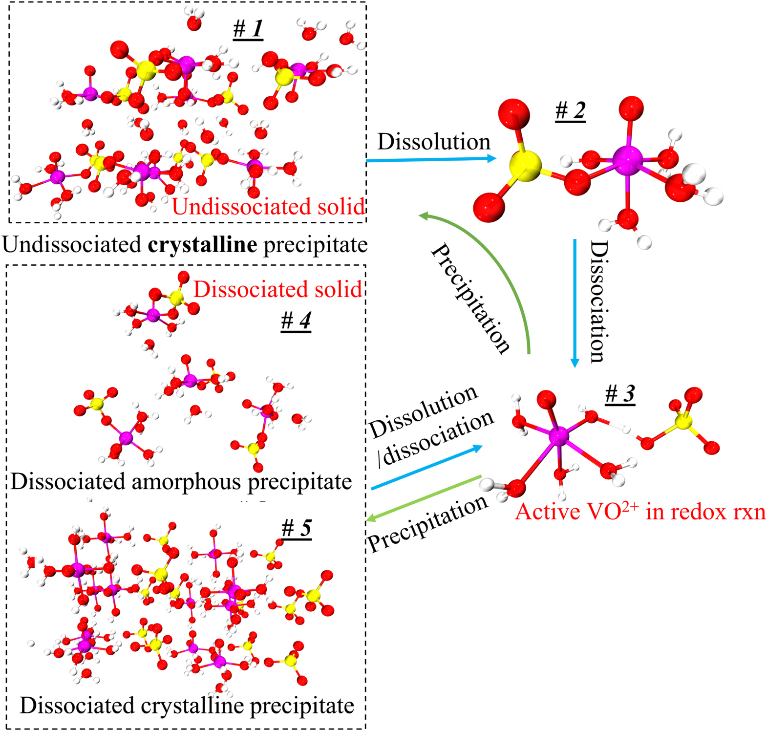
Figure 3. Possible mechanism of precipitation and dissolution process (magenta: vanadium; red: oxygen; yellow: sulfur; off-white: hydrogen).
Download figure:
Standard image High-resolution imageThe #1 structure in Fig. 3 is a crystal structure imported from the crystal database (ICSD #1043316). According to the Jahn-Teller effect, the sulfate ligand is bound to the vanadium center in the equatorial (horizontal) plane via one of its oxygen atoms, where the ligand binding strength is stronger than in the axial positions. 25 However, in a sulfuric acid solution, 1H and 17O NMR spectra indicate that the dissociated V(IV) cation exists in the form of the hydrated [VO(H2O)5]2+ cation, which is stable at sulfuric acid concentrations up to 3 M and temperatures ranging from ambient temperature to 67 °C. Furthermore, the sulfate anion and the hydrated vanadyl cation are found to exhibit little electrostatic contact indicating that the sulfate ligand is located primarily outside the first solvation shell. 26 The literature proposes that the sulfate ligand occupies the second solvation shell and is connected to the V(IV) cation via one of the equatorial water ligands, as shown in molecule #3. 26 Consequently, according to the crystal database and molecule #3, one could conclude that the undissociated VOSO4 crystal #1 dissolves in an aqueous solution to form the undissociated VOSO4 molecule #2, which could then dissociate to form molecule #3.
Two precipitation mechanisms for the dissociated vanadium salt molecules are suggested based on the characteristics described in Fig. 3. The first mechanism involves the process by which the dissociated molecules (#3) are precipitated back to the undissociated crystal (#1) through the route of the undissociated molecules (#2). The second mechanism involves the precipitation of the dissociated molecule #3 without direct recombination of the sulfate anion and the VO2+ cation. In this process, the [VO(H2O)5]2+ and the sulfate anion in the second shell may precipitate as either the ordered dissociated crystal #5 or the disordered dissociated solid #4 that has no clearly defined form. While the undissociated crystal #1 is the most thermodynamically stable form, the precipitation pathway from #3 to #2 and then to #1 is not kinetically favorable due to the energy required for the sulfate anion to displace the water ligand in the first hydrate shell. With sufficient time, the meta-stable low-crystallinity solids of dissociated molecules should ultimately form the stable undissociated crystal #1, where one of the water ligands is replaced by a sulfate anion. The results presented in Figs. 4 and 5 validate this hypothesis.

Figure 4. (a) Photos of different VOSO4 solids; (b) XRD spectra.
Download figure:
Standard image High-resolution image
Figure 5. Linear polarization curves of 1 M VOSO4 (total concentration)/3 M H2SO4 solution prepared from the different solids.
Download figure:
Standard image High-resolution imageTo confirm the processes proposed in Fig. 3, the XRD spectrum and electrochemical activity of various VOSO4 crystals were examined. The as-received VOSO4 ·xH2O shown in Fig. 4-a1 is the crystal powder that requires heating to completely dissolve and dissociate in an aqueous solution at high concentrations that are still below the solubility level. Without heating, the solid forms a temporary soluble solution that quickly precipitates after a short time. The flake-like compact crystalline solid shown in Fig. 4-a2 is the VOSO4 solid precipitated naturally in an oversaturated 3.2 M VOSO4/3 M H2SO4 solution without nucleation materials. Apart from the naturally precipitated VOSO4, other precipitates can be formed by introducing nucleation materials to the oversaturated solution. Initially, it was observed that the activated carbon nucleation material produced a low-crystallinity gel-like slurry. The solid extracted from this slurry was subsequently utilized as a nucleation material and was found to significantly accelerate the formation of the low-crystallinity precipitates (Fig. 4-a3) in a fresh oversaturated solution. After one month of storage in a vial with the saturated solution, this precipitate transformed into a more dehydrated solid (Fig. 4-a4). Finally, after six months of storage, the previously metastable low-crystalline solid transforms into a solid with an XRD pattern similar to that of the commercial undissociated solid (See Fig. 4b). Due to the length of the transformation process, we do not anticipate that this aspect will have an effect on the use of the solid/liquid storage method in an RFB where a discharge/charge cycle occurs daily or at most every few days for long-term applications. It is worth noting that the precipitates mentioned here are always retained in the saturated aqueous electrolytes that they precipitated from. The finding from this study indicates that some nucleation materials generate a low-crystalline VOSO4 precipitate whose structure is very efficient at promoting rapid precipitation from an oversaturated solution and has a very high dissolution rate with dilution.
The XRD spectra (Fig. 4b) of the four VOSO4 solids classify them into three groups: (1) as-received VOSO4 (black curve) and 6-month-stored VOSO4 (purple curve), (2) fresh and 1-month-stored low-crystallinity precipitates from oversaturated solutions with nucleation materials (red and blue curves), and (3) naturally precipitated VOSO4 (green curve). The blue and red vertical dashed lines marking the characteristic peaks of the spectra are used to link the two groups 1 and 2 above. In comparison to the as-received and 6-month-stored VOSO4, the fresh and 1-month-stored precipitates lack the peaks shown by the dashed blue vertical lines and have additional peaks denoted by the dashed red vertical lines. We neglect those shared peaks and summarize the distinct ones in Table II. The distinction between the first two groups resides in the ratio of the dissociated solids vs the total solids. This point will be explained by the results in Fig. 5. Our hypothesis indicates that the undissociated crystal, shown in Fig. 3, is the most thermodynamically stable but also the least favored kinetically. In Fig. 4b, the distinctive peaks remain unchanged after one month of storage. The main change was an increase in crystallinity that is attributed to the loss of free water molecules. However, even in a saturated solution, six months of storage allows the solid to completely convert into a solid with an XRD pattern very similar to the as-received solid, demonstrating that solid #1 in Fig. 3 is the final product of precipitation and that the process is quite slow. The gel-like precipitate has the lowest crystallinity, which agrees with the visual observation in Fig. 4a. Finally, because the naturally precipitated VOSO4 (green curve) solid has all of the typical peaks of the other two groups, we conclude that it must be a mixture of both solid groups.
Table II. Summary of distinct characteristic peaks of XRD spectra.
| Sample | 17°/18° | 20.5° | 23°/24° | 26.5° | 34.5° | 36° | 40° | 46° | 52° |
|---|---|---|---|---|---|---|---|---|---|
| As-received VOSO 4 | ✓ | ✓ | ✓ | ✓ | ✓ | ||||
| Fresh low-crystallinity VOSO 4 | ✓ | ✓ | ✓ | ✓ | ✓ | ||||
| 1-month-stored low-crystallinity VOSO 4 | ✓ | ✓ | ✓ | ✓ | ✓ | ||||
| 6-month-stored low-crystallinity VOSO 4 | ✓ | ✓ | ✓ | ✓ | ✓ | ||||
| Naturally precipitated VOSO 4 | ✓ | ✓ | ✓ | ✓ | ✓ | ✓ | ✓ | ✓ | ✓ |
While XRD can be used to investigate the crystal structure and determine the crystallinity, it cannot determine if the solid is made of dissociated ions or undissociated molecules. The linear polarization curves in Fig. 5 are used for this purpose. It can help verify and quantify the amount of the dissociated ions in these solids. The presence of more dissociated VO2+ cations correlates with increased electroactivity. As a result, a greater measured activity for the same total concentration of active vanadium (IV) salt implies a higher dissociation level. As shown in Fig. 5, the activity (slope of the polarization curve) of the as-received VOSO4 at RT/1- h stirring after being heated to 50°C for 10 min (red curve) is 40% greater than that at RT/1- h stirring without heating, indicating that the as-received VOSO4 contains a significant amount of undissociated molecules and cannot be completely dissociated by stirring at RT. In comparison, the low-crystallinity gel-like precipitate exhibits a 2X increase in activity when compared to the as-received VOSO4 at RT/1- h stirring, clearly indicating that the low-crystallinity precipitate contains more dissociated molecules in its solid.
Apart from the activity, the open-circuit voltage or OCV (crossover point on the x-axis) may give further evidence for the dissociation level, as the electrode potential correlates only with the dissociated vanadium ions in the solution. In all three V(IV) solutions, a fixed amount of V(V) sulfate (0.1 ml 0.2 M V(V) in 10 ml 1 M V(IV) solution) was added to fix the V(V) ion concentration in the solution, such that the electrode potential of the solution varies only by the V(IV) ion concentration as defined by the Nernst equation for this redox couple: So, a larger dissociated V(IV) ion concentration leads to a lower OCV. The order of the OCVs in Fig. 5 matches the order of the activity of the solutions determined by the slope of the polarization curves. The activity aspect mentioned here is critical for an RFB since it has an effect on the RFB's performance. If the breakdown of the solid results in the formation of mostly undissociated salt molecules, the RFB's performance would be adversely impacted.
![${E}_{{\rm{OCV}}}={E}^{\theta }+RT/\left(nF\right)\mathrm{ln}\left(\left[{\rm{V}}\left({\rm{V}}\right)\right]\left[{{\rm{H}}}^{+}\right]/\left[{\rm{V}}\left({\rm{IV}}\right)\right]\right).$](https://content.cld.iop.org/journals/1945-7111/169/11/110509/revision3/jesac97c6ieqn11.gif)
The XRD results in Fig. 4b demonstrate that the crystal structures of the fresh and one-month-stored precipitates from the oversaturated solution are distinct from those of the as-received VOSO4 and long-term-stored precipitates. The electrochemical activity and OCV from the linear polarization curves confirm that the crystal structure of the precipitates from oversaturated solutions is composed of dissociated VO2+, i.e., with the sulfate anion present only in the second solvation shell, while the as-received VOSO4 solid may be composed primarily of undissociated molecules that require additional thermal energy to break the vanadyl-sulfate equatorial bond. Thus, the #3#2#1 pathway in Fig. 3 is the most thermodynamically stable but kinetically unpreferable precipitation pathway, whereas the route #3↔#4 and #3↔#5 in Fig. 3 correspond to the desired precipitation/dissolution pathway of the dissociated precipitate from the oversaturated solution during a typical RFB operation. From the combination of the two pathways, the natural precipitate is believed to be a mixture of dissociated (#3) and undissociated (#2) salts. The low crystallinity (53%) of the precipitate induced by the dissociated salt molecules may reflect a mixture of the orderly and disorderly #4 and #5 precipitate structures.


After the proposed mechanism of dissociation/precipitation of VOSO4 was validated, the effects from the nucleation type, nucleation concentration, oversaturation level, and total concentration are explored. Although Table I provides some precipitation data, they were from visual observation of the solid formation. A more quantitative approach that can yield accurate results is needed. The OCV method to quantify the concentration of the dissociated V(IV) ion described earlier can be used to measure the rate of the change in the V(IV) ion concentration in the oversaturated solution during the precipitation process and to obtain the precipitation rate. Similar to the linear polarization curve measurement, a fixed starting ratio of V(V) to V(IV) was used in all solutions. In Fig. 6a, the concentration of V(IV), which was calculated from the measured OCVs, for the three cases considered decreases rapidly after the addition of the nucleation centers and finally stabilizes at the level that corresponds to the solubility of VOSO4 at the tested temperature and acid concentration.

Figure 6. (a) V(IV) concentration response with same nucleation center concentration and oversaturation level but with different types of nucleation centers and different initial sulfuric acid concentration; (b) precipitation rate averaged over every 5 min (black axis: the precipitation rate in 3 M H2SO4; red axis: the precipitation rate in 1 M H2SO4).
Download figure:
Standard image High-resolution imageThe slopes of the concentration curves in Fig. 6a averaged over a certain duration, shown in Fig. 6b vs time, describe the precipitation rate of V(IV) in the solution. Taking the black solid curve (precipitation of 3.2 M VOSO4/3 M H2SO4 initiated by the low-crystallinity dissociated salt) as an example, the general trend of the curve consists of a short initiation time followed by "V" shape response that includes a rapidly increasing precipitation rate that peaks (lowest point with the highest negative value) at some time later. The initiation time could be due to the low amount of the nucleation centers present initially. The precipitation rate accelerates once more solids are formed that provide more nucleation sites for precipitation and peaks when the decrease in the oversaturation level (i.e., the driving force for the process) in the solution becomes more dominant. The rate finally drops to nearly zero when the driving force approaches zero.
The dashed black curve, which is for the case where the as-received/undissociated VOSO4 is used as the nucleation material, shows a much longer initiation time, about 900 s. However, once sufficient nucleation sites are created, it shows a similar peak precipitation rate and decaying behavior. The precipitate appearance is also similar to the low-crystallinity type, as shown in Fig. 4-a2. This response conveys that the as-received material can also promote the creation of similar and suitable nucleation sites. It just takes a longer time to do this. The vanadyl complexes in the solution can be attracted to the adsorption sites of undissociated solid where the affinity between the undissociated nucleation centers and the dissociated cations may be lower, creating a longer adsorption or initiation phase. We postulate that once a layer of the dissociated salt is created over the surface of the undissociated nucleation material, it accelerates the precipitation of the dissociated ions. Combining this with the fact that the undissociated precipitate has the most thermodynamically stable structure but extremely slow precipitation and dissolution kinetics, one can hypothesize that any nucleation material that promotes fast precipitation will result in the formation of the metastable dissociated low-crystallinity solid.
The red curves in Figs. 6a and 6b are from the oversaturated solution with the same oversaturation VOSO4 level and dissociated nucleation material amount but in 1 M H2SO4 solution, i.e., 3.82 M V(IV) concentration in 1 M H2SO4 vs 3.2 M V(IV) concentration in 3 M H2SO4, of which the oversaturation levels are both 1.42 M. 24 Since the solubility of VOSO4 increases with lower sulfuric acid concentration, we hypothesize that while the oversaturation level (defined as the difference between the ion concentration and the soluble concentration) is the same, the faster precipitation rate of V(IV) in 1 M H2SO4 with the same oversaturation level, nucleation material concentration, and nucleation material type indicates that the V(IV) ion concentration itself can also affect the precipitation rate, which may be caused by the higher collision possibility in the solution of higher concentration. The commercial all-vanadium RFB employs 3 M H2SO4 as the supporting electrolyte to maintain high proton selectivity in the membrane (low permeability of vanadium species). 27 The proton conductivity of Nafion® membrane will increase with the acid concentration up to around 2.7 M and then decrease, which is a trade-off between proton concentration increase and water content loss caused by acid presence in the solution. 28 With this observation, the benefit of having a higher vanadium solubility and precipitation rate over the disadvantage of a higher vanadium ion crossover rate from the usage of a less ion-selective membrane separator deserves careful consideration when this hybrid solid/liquid storage is employed.
Since the types of nucleation centers in Table I and Fig. 6 demonstrate major effects on the morphology of the precipitates, the knowledge of the interaction between the vanadyl cations and the adsorbate is essential for the comprehension of the precipitation process. The graphene oxide (GO) is selected as the adsorbate in the current research because the activated graphitic carbon was found to be a suitable nucleation material to initiate the low-crystallinity dissociated precipitate, and the adsorption sites of GO, oxygen function groups, are easy to tune. Thus, the adsorption of VO2+ on the GO surface can be viewed as a simplified model of the precipitation process. The noncovalent interactions (NCI) are analyzed in this adsorption model. Figure 7a demonstrates the type of weak interactions among the vanadyl complexes and the adsorbate by showing the isosurfaces of sign where is the 2nd eigenvalue of the electron-density Hessian (second derivative) matrix identifying the types of interactions ( for the strong attractive interaction, for the dispersion force, and for the nonbonding region) and is the real space electron density gradient between the defined fragments calculated by Independent Gradient Model (IGM). 29


Figure 7. (a) sign(electrostatic attraction) isosurfaces (s = 0.01a.u.) of [VO(H2O)5]2+ on the graphene oxide (GO); (b) electron density difference isosurfaces of adsorbed [VO(H2O)5]2+ on GO (s = 0.006 a.u.; violet: electron increase; green: electron decrease) (Note: All the structures are optimized by the analytical linearized Poisson-Boltzmann (ALPB, water) and GFN2-XTB and then calculated by B3LYP-D3(BJ)/def2-TZVP for the single point energy).

Download figure:
Standard image High-resolution imageThe blue, green, and red colors on the isosurface indicate the strong electrostatic attractions like hydrogen bond, van der Waals force, and the nonbonded overlap (repulsion), respectively. Figure 7a shows that the electrostatic attraction exists between the anchoring points (O-sites of GO) and vanadyl complexes for the case of four vanadyl complexes on a GO surface. At the same time, the vanadyl complexes attracted by the adjacent adsorption sites also demonstrate inter-complex attraction. The electron density difference, is calculated for this case in Fig. 7b. The electrons are transferred from the GO (green isosurface) via the oxygen functional groups, including −COOH, −OH, and C=O groups (green isosurface), to the vanadyl cations and their water ligands (violet isosurface) thus increasing the electron density of the complex. The higher electron density on the vanadyl complexes results in a higher affinity to the electron-deficient cations in the neighboring solution layer and may slightly reduce the attraction effect to the electron-abundant sulfate anion ligand to maintain the dissociated configuration in the formation of low-crystallinity dissociated sediment.

On the basis of Fig. 7 for four adsorbed [VO(H2O)5]2+ on the GO surface, two free [VO(H2O)5]2+ complexes, namely Free #1 and Free #2 in Fig. 8a, and some free water molecules are added to the system for the tight-binding DFT molecular dynamics process evaluation using XTB. The decreasing distances of free VO2+ cation/adsorbed VO2+ cation (red curve in Fig. 8b) and free VO2+ cation/COOH of GO (blue curve in Fig. 8b) suggest that the free V(IV) complex is attracted to the adsorbate by the adsorbed cation and the anchoring points simultaneously. Meanwhile, the distance between the adsorbed V(IV) cations and their anchoring point remains stable during the whole MD process (green curve in Fig. 8b), indicating a steady electrostatic attraction. Initially, the adsorbed V(IV) cations #2 and #3 are attracted to the two carboxylic groups of the same benzene ring, respectively. The distance between these two V(IV) cations (purple curve in Fig. 8b) becomes even closer during the MD process which indicates that a high density of adsorption sites on the adsorbate may result in a more compact or crystalline precipitate (template effect). Figure 8c describes the precipitate formation process that the free V(IV) cations are gradually adsorbed on the adsorbate surface and the impact of the density (number and proximity) of the active sites on the surface could have on the formation of a compact adsorption layer and the resulting structure of the precipitate solid and the precipitation rate of the ions.

Figure 8. (a) Adsorption/precipitation configuration (green: hydrogen); (b) bond distance variations (each frame represents 50 fs); (c) geometry change (blue represents the free vanadium atoms).
Download figure:
Standard image High-resolution imageThe driving force of the adsorption in the precipitation process is further investigated in Fig. 9. Initially, the free vanadium complex cluster only shows interaction with the surrounding free water molecules instead of the adsorbed vanadyl cations and the GO's functional groups in Fig. 9a. Later, the strong electrostatic attraction appears between the free VO2+ complexes and the adsorbed vanadyl cations/functional groups. Complexes #1 and #3 in Fig. 9b are the examples of the attraction between the free cations and the adsorbed ones, while complex #2 describes the attraction between the free cation and the carboxylic group of GO. The blue (strong electrostatic attraction) isosurface diluted by the green (weak van der Waals force) coating in Fig. 9b shows that the interaction between the free V(IV) complexes is weakened compared to that of the initial free vanadium cluster (circled in Fig. 9a) due to the re-adjustment of the electron density after the adsorption of the free vanadium complex.
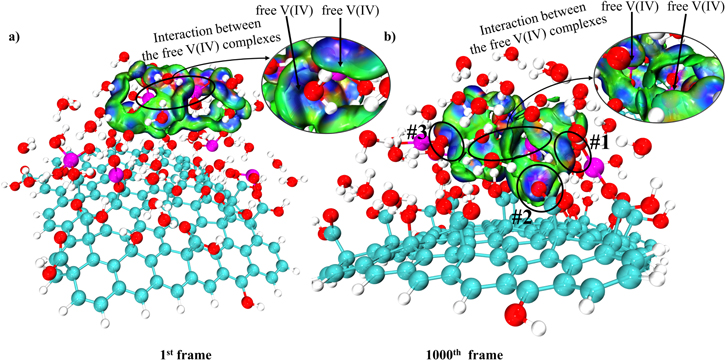
Figure 9. (a) sign (electrostatic attraction) isosurfaces (s = 0.01a.u.) of the 1st frame of MD; (b) sign (electrostatic attraction) isosurfaces (s = 0.01a.u.) of the last frame of MD. (The same color scale as in Fig. 7a is used here).


Download figure:
Standard image High-resolution imageThe precipitation mechanism study so far was performed with GO adsorbate as a simplified model, and the effect of the anion-like sulfate ligand was neglected. In the future, the precipitation process with dissociated salt as the adsorbate, the explicit sulfate anion ligand, and the existence of the counter cation (V(IV)/V(V) redox couple) in a larger solvation box will be carried out. Besides the understanding of the nature of the precipitation process shown above, it may reveal a harsh reality: attempts to increase the vanadium concentration above the solubility limit through the use of stabilizing agents may eventually fail in the long run due to the widespread presence of oxygen functional groups on all types of carbon electrodes that attract the vanadium cations. 30 Due to the inherent nature of activated carbon electrodes as nucleation sites, the temperature-swing concept is an appealing method of increasing the energy storage density and operating concentration of RFBs.
With a newly learned knowledge of the mechanism of vanadium salt precipitation and dissolution, an H2-V flow battery was constructed as shown in Fig. 2 to demonstrate the viability of the solid-liquid storage idea. Charge and discharge cycles were conducted using the constant-voltage mode to determine the maximum steady-state current density that can be achieved in this hybrid system. The results are presented in Fig. 10. The most noticeable feature in the RFB with the hybrid storage system is the presence of a constant current plateau during the charge/discharge early stage, showing that the fast-enough in-time solid dissolution process stabilizes the electrolyte concentration prior to the complete consumption of the solid phase. After the consumption of the added solid, the discharge current exhibits the normal behavior of an RFB, basically, the overpotential increases gradually with decreasing V(V) reactant concentration or increasing charge capacity and then more rapidly at the end of charge/discharge owing to mass-transport limitation. The variability in the current density vs time graphs is due to the delayed response of the temperature-controlled hot water bath, which results in the vanadium electrolyte and flow batteries temperature variation of 37 °C–42 °C. Additionally, the electrodes must be activated and the membrane needs to be humidified, resulting in the first cycle's somewhat worse performance than the subsequent two cycles, which exhibit repeatable patterns regardless of the current density or specific capacity vs time.

Figure 10. Cycling test of charging and discharging performances at 1.3 V and 0.7 V with 10 mA cm−2 as the cut-off current density, respectively (left y-axis: current density vs time; right y-axis: specific capacity vs time).
Download figure:
Standard image High-resolution image
The electric current density plateau region of the charging process in Fig. 10 is integrated to around 41% of the total vanadium charging capacity, which very closely corresponds to the theoretically estimated 44% of the capacity as the extra dissociated solid added to the system. As a comparison, the current density plateau integration of the discharging process is shorter than that of the charging stage, ∼34% vs ∼41%. Initially, we suspected that the current density plateau of V(V) to V(IV) during discharge might be attributed to the dissolution process of the precipitated V(V) sulfate salt, since V(V) sulfate has a similar solvation structure with that of V(IV) sulfate. 31,32 At the end of the complete charging process (∼100% SOC, not shown in Fig. 10), we observed that the electrolyte became highly viscous; however, there was no solid V(V) sulfate found on the bottom of the storage container. The 30-min centrifuge at 6000 RPM did not create a separation between the solid and liquid. One can infer that either the possible precipitate consists of nano-scale particles which cannot be separated from the solution by the centrifuge OR there is no solid salt generated in the charging process. Skyllas-Kazacos et al. found that the high sulfuric acid concentration can significantly enhance the upper limit of V(V) concentration. 33 The sulfuric acid concentration of the fully charged electrolyte, in this case, reaches 6.2 M, which stabilizes V(V) product and avoids possible precipitation. The literature also points out that the higher V(V) concentration decreases the cathodic peak current height in the CV scan, implying the possible formation of new electrochemically inactive species at the increased concentration. 33 During the discharge operation, the conversion from the inactive V(V) sulfate to the active species may result in the electric current density plateau from a relatively constant concentration of the active V(V) reactant. Additionally, because the electrochemically inactive V(V) species is soluble, this conversion can occur even at the electrode surface, which may explain why the discharge performance is superior to the charging performance, which requires the dissolution of the solid V(IV) salt in the storage tank and the mass transport of V(IV) ions from the solid section across the separator to the liquid section. Additional studies will be conducted in the future to further explore the unique mechanism of V(V).
Conclusions
A solid-liquid storage approach that stores both solid and liquid phases of the active materials in the electrolyte tank and pumps only the liquid electrolyte to the flow battery was proposed to address the lower energy storage density issue of redox flow battery systems. This approach was applied and investigated for the V(IV)/V(V) sulfate electrolyte. The investigation revealed the following findings: 1) the possible precipitation and dissolution routes of V(IV) sulfate involve dissociated and undissociated VOSO4 molecules; 2) the V(IV) electrolyte prepared with the dissociated precipitate exhibits greater electrochemical activity than the electrolyte prepared with the undissociated salt; 3) the highest precipitation rate of V(IV) sulfate is triggered by the low-crystallinity dissociated solid VOSO4; 4) the precipitate V(IV) will be of the low-crystallinity form if the precipitation is rapid enough to prevent the sluggish kinetics of re-bonding of the vanadium cation and the sulfate anion in the secondary solvation shell; 5) the electrostatic interaction among the vanadium cations and the charged sites on the adsorbates is the primary driving force for the V(IV) sulfate precipitation; 6) attempts to boost the vanadium concentration over the solubility limit by using additives may ultimately fail due to the extensive presence of oxygen functional groups that attract the vanadium cations on all types of carbon electrodes; 7) the dissolution rate of the dissociated V(IV) sulfate solid is fast enough to stabilize the electrolyte concentration and increases capacity when this approach was demonstrated in a H2-V flow battery; 8) there is no V(V) solid precipitate in the fully charged vanadium electrolyte due to the high solubility of V(V) sulfate salt in the high H2SO4 concentration; 9) the conversion from the soluble electrochemically-inactive V(V) salt to the active V(V) salt instead of the dissolution of solid stabilizes the aqueous V(V) concentration during the discharge. In summary, the effectiveness of the hybrid storage concept has been demonstrated in an operational RFB. Meanwhile, other fundamental scientific concerns have arisen that will need to be addressed in the future, such as the chemical composition of a high-concentration V(V) sulfate electrolyte and the comprehensive mechanism of the low-crystallinity V(IV) precipitation/dissolution process.
Acknowledgments
The authors would like to recognize the financial support from National Science Foundation under Grant No. CBET-2024378.