

Abstract
The thermal instability of polymer separators severely threatens the safety characteristics of lithium-ion (Li-ion) batteries. Separators will melt, shrink, vaporize, and collapse under high temperatures, leading to internal short circuits and thermal runaway catastrophes of the cell. Therefore, the amelioration of battery safety challenges benefits from a fundamental understanding of separator behaviors under thermally abusive scenarios. This work investigates the role of separator thermal stability in modulating Li-ion cell safety performance. Three types of separators made of commercially available cellulose, trilayer polypropylene/polyethylene/polypropylene, standard polypropylene, and an in-house modified graphene-polydopamine coated separator are fabricated in custom single layer pouch cells and subjected to accelerating rate calorimeter (ARC) tests to investigate dynamic thermo-electrochemical interactions. The safety hazards of 18650 cylindrical cells assembled with different types of separators are predicted using a verified ARC computational model to compare the effects of separator heat resistance on cell-level thermal runaway risks. This study reveals the thermally robust mechanisms of diverse separator microstructures, indicating how the in-house modified graphene-polydopamine coated separator significantly enhances the safety limits of Li-ion batteries.
Export citation and abstract BibTeX RIS
Widespread deployment of lithium-ion (Li-ion) batteries is critical to the accelerated electrification of transportation, energy storage, and military systems such as electric vehicles, 1 electric vertical takeoff and landing aircraft, 2 grid-scale renewable energy storage, and unmanned autonomous vehicles. The usage of batteries in such applications has the potential to drastically reduce greenhouse gas emissions, 3 decrease the probability of power outages, and increase the capabilities and endurance of defense systems. However, trade-offs exist among energy density, cost, fast charge capability, cycle life, performance, and safety that must be balanced through comprehensive optimizations to maximize the potential of Li-ion batteries in next-generation electrochemical energy storage and conversion devices. 4 The frequent occurrence of safety events is the greatest challenge that must be addressed in the development of advanced Li-ion cell chemistries and designs. Significant research efforts are underway to develop innovative functional materials and predictive battery management systems. 5
The separator is one of the essential components in Li-ion batteries to protect against electrochemical and thermal failure while allowing high discharge rates and low self-discharge rates. Ionic flow, driven by diffusion and electromigration, is permitted through the electrolyte which fills this porous membrane, while the electrodes are physically insulated to prevent hazardous internal short circuit (ISC) events that may lead to thermal runaway events. Nowadays, most commercially available separator materials in battery markets are made of polyolefins, such as polyethylene (PE), polypropylene (PP), and hybrid PP/PE. These polymer separators usually benefit from high porosity and permeability, excellent wettability with non-aqueous electrolyte, strong structural stability, stable chemical properties, smooth interface with the electrode, and low transport resistance. 6 Nevertheless, many applications and systems are still avoiding Li-ion battery packs due to their inherent poor safety performance, which often leads to catastrophic thermal runaway propagation. A frequent cause of thermal runaway is the collapse of separator integrity due to the low puncture strength and poor thermal stability at high temperatures.
Although the introduction of ceramic coatings (Al2O3, SiO2, TiO2) has successfully reinforced the mechanical and thermal robustness of separators, 6 they are still vulnerable when subjected to extreme physical, thermal, and electrical abuse conditions. For instance, separators might be damaged and pierced after high-speed impacts. The deformation can lead to ISC and then thermal runaway, resulting in the emission of toxic vapors, fires, and molten ejecta. If Li-ion batteries are overcharged or overdischarged, lithium and copper dendrite growth might penetrate porous separators and contact the opposite electrode to cause ISC. In high-temperature environments, separators will degrade through multi-step morphological and structural changes. For a conventional PE-based separator, pores start to be blocked when the PE melts at around 130 °C, which dramatically impedes ionic transport and increases the internal resistance of the cell. 7 This shutdown function will partially cut off the overloading current and ionic flow to help delay ISC-induced safety events, but this effect is almost always insufficient to prevent the upcoming failure disaster. If cell temperature keeps rising, separators will start to melt, vaporize, and shrink from the edges until the final collapse of carbon chains results in a massive ISC. The following exothermic reaction breaks down the electrolyte and further contributes to a quick release of the cell energy, causing intensive heat generation and catastrophic thermal runaway. Therefore, the thermal safety characteristics of Li-ion batteries significantly depend on the thermal stabilities of separators under abusive conditions.
A large amount of research and development have been conducted to help elucidate the relationship between separator properties and battery safety performance to push the safety limits of Li-ion cells through engineering modifications on separators. Cutting-edge innovations are now developing heat-resistant separators, mainly based on organic, inorganic, or hybrid organic-inorganic materials 8 to realize tunable pore structures, 9 cross-linked fibrous networks, 10,11 and high curvature skeletons 12 with improved thermal tolerances. State-of-the-art inorganic separators made of glass fiber, 13,14 cellulose, 15 zirconia, 16 paper 17 substrates, and composite organic-inorganic separators made of polysulfonamide/cellulose 18 and polyformaldehyde/cellulose 19 exhibit high ionic conductivity, enhanced mechanical properties, decent wettability with non-aqueous electrolyte and extended cycling stabilities. Frontier organic separators made of polyimide, 10,20,21 polyphenylene sulfide, 22 polybenzimidazole, 23,24 polyester, 25 polydopamine, 26 poly(ether ether ketone), 27 and aramid 28 present high tortuosity and porosity that satisfy interfacial compatibilities and improved thermal stabilities by showing strong flame-retardant and anti-shrinkage properties. Moreover, separators with diverse doped nanoparticles and coating layers, such as ceramics of SiO2, 29–33 Al2O3, 34–36 Sb2O3, 37 AlOOH, 38 biomass of ethylcellulose, 39 zeolitic imidazolate framework 40,41 and vermiculite 42 are also practical strategies to reform their safety characteristics. These modifications can optimize contact angles of non-aqueous electrolyte droplets for better wettability with non-aqueous electrolytes, while suppressing the thermal shrinkage and deformation of the woven skeleton at high temperatures above 200 °C. The development of functional separators keeps moving forward to prevent cell-level catastrophic thermal runaway events by introducing particular safety features, such as rapid thermal shutdown, 43–47 phase-change endotherm, 48 and early detection of ISC caused by inter-electrode dendrite growth. 49–51
Although modified graphene-coated separators have been widely applied in lithium-sulfur (Li-S) batteries to inhibit polysulfide shuttle effects 52–56 and in lithium-metal (Li-metal) batteries to improve electrical conductivity and cycling lifetime, 57,58 their high-temperature thermal stabilities compared with common polyolefin separators remain elusive. In this research, we fabricate single-layer Li-ion pouch cells encapsulated with four types of separators, including a cellulose separator, a trilayer PP/PE/PP separator, a standard PP separator, and an in-house modified graphene-polydopamine coated separator. Microstructures and transport characteristics of these separators are visualized and analyzed using scanning electron microscopy (SEM). Accelerating rate calorimeter (ARC) tests are carried out on all single-layer pouch (SLP) cells to investigate dynamic thermo-electrochemical interactions under thermally abusive conditions while revealing the high-temperature stabilities of each type of separator. Destructive physical analysis (DPA) is conducted on all SLP cells subjected to ARC experiments to assess separator morphological change and other vital factors causing cell failure. A verified ARC model is applied to simulate the thermal runaway behaviors of 18650 cylindrical cells assembled with these separators to predict their significant role in dictating cell-level safety risks. This study highlights the outstanding thermal robustness of the tailored graphene-polydopamine coated separator compared with other commercially available separators, nominating it as a strong candidate for safer next-generation Li-ion, Li-metal, and Li-S batteries.
Experimental
Fabrication of separators and SLP cells
The cellulose separator, trilayer separator, and standard separator were obtained from Battery Innovation Center (BIC). The thickness of the cellulose separator was 30 μm when measured with a micrometer under pressure, while the trilayer separator and the standard separator were rated to be the same thickness of 25 μm, as provided by the manufacturer. For the in-house modified graphene-polydopamine coated separator, the PP separator was floated on 10 M dopamine solution with a pH of 9. The separator remained floated for 6 h, after which it was washed with distilled water and dried in the oven at 50 °C for 12 h. After the drying, it was coated with 90:10 graphene:carboxymethyl cellulose solution and then dried in the oven at 50 °C for another 12 h. 57,58 The thickness of the graphene-polydopamine coated separator could be calculated as 35 μm, which included 25 μm of PP substrate and 10 μm of the coating layer. As these four types of separators were composed of different materials, with various production methods, and by diverse manufacturers, obtaining all of them with identical thicknesses was not necessarily realistic.
Five 85 mAh SLP cells with each type of separator introduced above were fabricated at BIC. The dimensions of anode sheets, cathode sheets and external aluminum pouch were 4 × 6.5 cm, 3.5 × 6.5 cm, and 5.5 × 9.5 cm, respectively. The anode was made of graphite coated on a copper current collector, and the cathode was made of LiNi0.5Mn0.3Co0.2O2 (NMC532) coated on an aluminum current collector. The graphite anode was 80–81 μm thickness with a 10 μm copper current collector and an average mass loading of 10.5 mg cm−2 (9.8 mg cm−2 active material). The NMC532 cathode was measured to be 85 μm thickness with a 12 μm aluminum current collector and an average mass loading of 21.1 mg cm−2 (19.8 mg cm−2 active material). The final thickness of the actual cell was simply the addition of the anode, cathode, and tested separator dimensions (190 μm for cells with trilayer and standard separators, 195 μm for cells with cellulose separators, and 200 μm for cells with graphene-polydopamine coated separators). We did not measure the thickness of a completed pouch directly as it was fairly detrimental to apply high point pressure to a delicate cell that we intended to test. A standard electrolyte of 1 M LiPF6 in EC/EMC (v/v 3:7) solvent from BIC was injected into all SLP cells with a controlled volume of 2 ± 0.1 ml that flooded the entire inner spaces.
Microscopic characterization of separators and electrodes
An FEI Nova NanoSEM 200 at Purdue Electron Microscopy Facility was used to characterize surface microstructures of prepared separators and electrodes. Microstructures of cellulose separator, trilayer separator, standard separator, and modified graphene-polydopamine coated separator are presented in Fig. 1, while particle morphologies and elemental mapping of SLP cell electrodes are imaged and quantified in Fig. S1 and Table SI (available online at stacks.iop.org/JES/169/090521/mmedia).

Figure 1. Cross sectional (A)–(D) and top view (E)–(H) of separator microstructures under SEM imaging. A and E: Cellulose separator; B and F: Trilayer separator; C and G: Standard separator; D and H: Modified graphene-polydopamine coated separator.
Download figure:
Standard image High-resolution imageConditioning tests of SLP cells
Before the ARC experiments, all SLP cells with four different types of separators were subjected to conditioning tests to form a uniform solid-electrolyte interphase (SEI) and measure the charge/discharge capacity, coulombic efficiency, and internal resistance (IR). SLP cells were cycled three times between 2.7 V to 4.2 V through constant current-constant voltage (CC–CV) charge and CC discharge methods at a 0.08C rate (7.0 mA). The IR was measured at a 50% state of charge (SOC) during the discharge phase of each cycle by applying a 1.5C (127.5 mA) current pulse for 0.1 s that originates a spike on the current signal. The performance of a typical SLP cell during the conditioning test is shown in Fig. S2 and Table SII. After conditioning tests, SLP cells were CC–CV charged to 4.2 V at a 0.08C rate before conducting ARC experiments.
ARC experiments and post-mortem analysis
After conditioning tests, fully charged SLP cells were subjected to thermal safety experiments using an EV + ARC manufactured by Thermal Hazard Technology (THT). The initial and maximum temperature of the heat-wait-seek (HWS) mode was 100 °C and 300 °C, respectively, with a 20-min wait step. The temperature rate sensitivity was 0.02 °C min−1, and the temperature interval for each heating step was 5 °C. Cell voltages were monitored in operando to record the ISC-induced voltage signal fluctuations and thus reveal the thermal robustness of different types of separators. Burnt SLP cells after ARC tests were extracted from the calorimeter and opened in an argon-filled glovebox (H2O < 0.1 ppm, O2 < 0.1 ppm) for post-mortem analysis.
Thermal Abuse Model
An ARC-oriented thermal abuse model primarily based on the inter-electrode crosstalk mechanism is adopted to simulate the ARC thermal runaway behaviors of 3.6 Ah 18650 cylindrical Li-ion cells assembled with four types of separators. The applied ARC model has been thoroughly validated in our previous publication, 59 indicating that the proposed model can decently match the onset of thermal runaway and maximum temperature of the ARC experimental profile obtained from a fully charged 3.6 Ah 18650 cylindrical Li-ion cell. The significance of this simulation is to predict the thermal safety characteristics of commonly used 18650 li-ion cells assembled with different types of commercially available separators, while highlighting the reinforced cell-level thermal safety factors if the modified graphene-polydopamine coated separator is employed. All modeling parameters are precisely the same and can be fully accessed from our previous work, 59 except that the critical temperature of massive ISC changes with the heat resistance of each separator revealed in experimental sections.
Essentially, thermal activities of typical chemical reactions can be comprehensively described by the following governing equations from Eqs. 1 to 4 based on classical Arrhenius theory,


where  is the time,
  is the dimensionless concentration of reactant with
  as the initial value,
  is the frequency factor,
  is the activation energy,
  is the universal gas constant,
  is the instantaneous temperature,
 ![$f[c\left(t\right)]$](https://content.cld.iop.org/journals/1945-7111/169/9/090521/revision2/jesac8edfieqn8.gif) is the mechanism function,
is the mechanism function,  are reaction orders,
  is the reaction enthalpy, and
  represents the instantaneous specific heat flow. Kinetic parameters of all reactions involved in this model and their characteristic mechanism functions with initial reactant concentrations are summarized in Tables SIII and SIV.
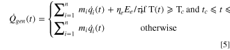
Furthermore, the cell temperature response in this ARC model follows fundamental energy conservation equations described from Eqs. 5 to 7,


where  is the instantaneous total heat generation rate in the cell,
  from 1 to
  represents each involved reaction,
  is the mass of any reactant,
  is the instantaneous specific heat flow of any reaction,
  is the percentage of total electric energy released during massive ISC.
  is the total electric energy stored in the fully charged 3.6 Ah 18650 cell, which is calculated based on the product of capacity (3.6 Ah) and nominal voltage (3.7 V).
  is the average ISC period after separator collapse,
  is the critical temperature where massive ISC occurs,
  is the critical time when massive ISC occurs,
  is the specific heat capacity of the cell,
  is the mass of the cell,
  is the instantaneous temperature of the cell,
  is the overall heat transfer coefficient (both convection and radiation) between the cell and the ARC chamber,
  is the surface area of the cell,
  is the instantaneous temperature of the ARC chamber, and
  is the initial temperature of the cell. Modeling parameters of virtual ARC setup, cell specifications, and the mass of the reactant for each reaction are summarized in Tables SV, SVI, and SVII, respectively.
Results and Discussion
Transport characteristics of separator microstructures
SEM imaging was used to capture cross-sectional and top views of separator microstructures as shown in Fig. 1. The cellulose separator is around 26 μm thick and consists of cellulose fibers that are non-woven strands, as shown in Figs. 1A and 1C. The side view of the separator reveals large, nonuniformly distributed pores and the top view shows relatively smaller but randomly distributed pores. The maximum pore size is around 1 μm and complex strand morphologies result in low resistance to ionic transport but high tortuosity. The trilayer separator consists of a PP layer followed by a PE layer and one more PP layer, as shown in Figs. 1B and 1D. The thicknesses of the layers are about 9 μm, 7 μm, and 5 μm, respectively. The trilayer separator shows a compact layered structure with distinct boundaries from the side view, and a more organized porous distribution from the top view than the cellulose separator. The maximum pore size of around 100 nm indicates a higher ionic transfer resistance than the cellulose separator, but the regular woven morphology reduces tortuosity and increases the effective ionic diffusivity. Figures 1C and 1G show that a standard separator with a single-layer PP skeleton also displays a compact structure from the side view and an organized porous distribution from the top view, similar to what was observed in the trilayer separator. However, the maximum pore size around 200 nm demonstrates a higher porosity than the trilayer separator to facilitate ionic transport through the woven structures. The tailored graphene-polydopamine coated separator is made of a conventional PP separator with one side soaked in polydopamine (PDA) solution followed by a slurry coating of graphene nanoflakes and carboxymethyl cellulose, as shown in Fig. 1D. In this modified separator, the basic PDA solution reacts on the surface of the PP separator to create a hydrophilic surface during aqueous slurry coatings while reducing the pore size down to 100 nm. In Fig. 1H, top flakes of conducting graphene are visible with a layer thickness around 10 μm. The small pore size and top conducting layer have been reported to benefit the maintenance of low-temperature electrochemical stability when assembled in the Li-metal cell. 57,58 They are also likely to enhance high-temperature thermal stability and push cell-level safety limits by maintaining mechanical robustness and anti-shrinkage properties under abusive conditions.
Thermo-electrochemical Interactions of SLP cells with diverse separators
Figure 2 shows the thermal signatures of three SLP cells (marked as cell C-1, cell C-2, and cell C-3) assembled with a cellulose separator during ARC tests. This separator is specifically designed to minimize shrinkage under thermal abuse conditions. Figures 2a and 2b show the thermo-electrochemical interactions of cell C-1 as the ARC test was conducted while monitoring the cell voltage response. A sustaining exothermic phase starting at 148 °C could be identified from the temperature profile, which might be caused by SEI thermal decomposition and further reactions between organic electrolyte and exposed lithiated graphite. 60 The cell voltage drops from 4.01 V to 0.00 V within the temperature range of 107 °C to 167 °C. Specifically, the cell voltage experiences a slight decline from 4.01 V to 3.57 V between 107 °C and 133 °C but maintains above 3.00 V until 156 °C. After that, the cell voltage rapidly decreases to 1.93 V at 160 °C, and finally falls to 0.00 V at 167 °C. This voltage profile indicates that a large-scale shrinkage of the cellulose separator might be initiated when the cell temperature is greater than 156 °C, and ultimately causes a massive ISC at 167 °C. Results of the DPA shown in Fig. S3 indicate that the cellulose separator does not completely vaporize at the end of the tests. It maintains its structural integrity, but a drastic shrinkage can be observed, which will cause direct contact between electrodes and cause cell failure. The active material of the graphite coating layer delaminates, flakes, and falls off the copper current collector, while severe delamination is observed between the NMC532 coating layer and the aluminum current collector. Figures 2c and 2d present the thermo-electrochemical interactions of cell C-2 until the final temperature of 300 °C. This cell shows a continuous self-heating phase starting from 152 °C, which is again likely to be caused by anode-centric exothermic reactions. 61 The cell voltage drops from 4.03 V to 0.00 V within the temperature range of 107 °C to 183 °C. Similar to the behaviors of cell C-1, the voltage of cell C-2 suffers a slight decline from 4.03 V to 3.76 V between 107 °C and 127 °C, but stays above 3.00 V until 164 °C. After that, the cell voltage rapidly decreases to 0.28 V at 170 °C, and finally falls to 0.00 V at 183 °C. This voltage profile indicates that the large-scale shrinkage of the cellulose separator occurred between 164 °C and 170 °C. Results of the DPA in Fig. S3 again show that the cellulose separator is not completely vaporized at the end of the tests. The skeleton maintains intact but suffers from an intensive thermal contraction, triggering massive ISC events. Delamination and fragmentation of coating layers are visible on both electrodes, which can somewhat be explained by the decomposition of the PVDF binder 62,63 that contributes to this physical contact loss.

Figure 2. Time-dependent voltage and temperature of (a) cell C-1, (c) cell C-2, and (e) cell C-3 during ARC tests, followed by temperature-dependent voltage and temperature rate of (b) cell C-1, (d) cell C-2, and (f) cell C-3 during ARC tests assembled with cellulose separator. DPA of each cell after ARC tests is shown in Fig. S3.
Download figure:
Standard image High-resolution imageFigures 2e and 2f show the thermo-electrochemical interactions of cell C-3 until a temperature of 300 °C with the cell voltage response. Five exothermic phases that sequentially start at 172 °C, 197 °C, 217 °C, 257 °C and 297 °C could be identified from the temperature profile, which is probably triggered by the anode-electrolyte interaction, cathode-electrolyte reaction, and the subsequent inter-electrode chemical crosstalk event due to the unfavorable oxygen liberation. 59,64 We assume the reduced amount of exotherm in cell C-3 is caused by less amount of electrolyte remaining in the aluminum pouch, which declines the heat release from anode-electrolyte and cathode-electrolyte interactions under high temperatures. Although we injected a controlled volume of 2 ± 0.1 ml electrolyte in every cell that flooded the entire separator and electrode areas, some electrolytes might be sucked out when we applied surface adhesion to the mylar and extra free spaces between the aluminum pouches with vacuum operations. Nonetheless, the remaining electrolyte in cell C-3 was still sufficient to wet the entire separator and electrode-separator interface properly, so it presented a regular electrochemical performance during the conditioning test that prevented us from being aware of this defect. However, we believe this minor drawback in cell C-3 does not impact the accurate quantification of separator thermal stabilities because the thermal behaviors of separators were essentially temperature-dependent. We are investigating thermal tolerances of separators by monitoring the cell voltage drop as a function of cell temperature rise instead of cell exothermic phases. Therefore, less heat release caused by the reduced amounts of electrolyte in the cell C-3 does not significantly impair the precise determination of characteristic temperature ranges where separators start to shrink, melt, vaporize and collapse. We are still able to observe similar and consistent thermal behaviors of cellulose separators in Figs. 2b, 2d, and 2f. The cell C-3 voltage stays above 3.91 V between 107 °C and 170 °C, but suddenly drops to 0.00 V at 179 °C with some data noise suggesting a micro ISC event. This voltage profile implies that the dominant shrinkage of the cellulose separator occurred between 170 °C and 179 °C. This temperature range is slightly higher than those of cells C-1 and C-2, but falls within reasonable bounds given the complex and stochastic nature of TR events. Results of the DPA in Fig. S3 show the residue of the cellulose separator with severe contraction at the end of the tests. Delamination of the crispy coating layer on both electrodes matches the previous observations. Taken together, the three ARC tests indicate that the cellulose separator is inclined to collapse within the temperature range of 156 °C to 179 °C.
Figure 3 depicts the thermal signatures of three SLP cells (marked as cell T-1, cell T-2, and cell T-3) assembled with a trilayer separator. This separator is particularly designed to terminate the current flow and ionic transport under abusive conditions by melting the middle PE layer and blocking the pores of the remaining PP structure. Figures 3a and 3b show the thermo-electrochemical interactions of cell T-1 until the temperature of 300 °C while recording the voltage decline. A single exothermic phase starting from 142 °C could be observed from the temperature profile, which might be caused by SEI decomposition and the following anode-electrolyte interactions. 65 Overall, the cell voltage drops from 4.10 V to 0.00 V within the temperature range between 110 °C and 165 °C, with frequent noise occurring between 110 °C and 142 °C. We assume it indicates the micro ISC event in cell T-1 due to the characteristic melting of the intermediate PE layer in the trilayer separator. 66 There are some possible reasons why we do not observe similar voltage behaviors in other two cells. First, the high-temperature melting of PE layers in cell T-2 and T-3 are probably mild and gentle so they do not significantly deform the external PP layers and electrode-separator interface, thus the micro ISC in these cells are not remarkable. Second, more external pressure might be applied when we fixed cell T-1 in-between the two metal bars of the pouch cell holder and put it into the ARC chamber for testing. It likely compacted the cell configuration, reducing the distance and free spaces between two electrodes and thus making the micro ISC event more sensitive and easily detected. As a result, the voltage drop in cell T-1 from 3.81 V to 0.00 V between 142 °C and 165 °C indicates the high-temperature collapse window of this trilayer separator. Results of DPA in Fig. S4 show that the trilayer separator has been totally vaporized at the end of the test. Massive delamination of the coating layer could be observed from the NMC532 cathode, while the graphite anode becomes brittle and stiff.

Figure 3. Time-dependent voltage and temperature of (a) cell T-1, (c) cell T-2, and (e) cell T-3 during ARC tests, followed by temperature-dependent voltage and temperature rate of (b) cell T-1, (d) cell T-2, and (f) cell T-3 during ARC tests assembled with trilayer separator. DPA of each cell after ARC tests is shown in Fig. S4.
Download figure:
Standard image High-resolution imageFigures 3c and 3d illustrate the thermo-electrochemical interactions of cell T-2 during the ARC test. Similarly, a single exothermic phase starting from 142 °C could be identified. The cell voltage drops from 4.11 V to 0.00 V within the temperature between 110 °C and 170 °C. Micro-ISC is observed between 135 °C and 155 °C, showing the onset of shrinkage of the trilayer separator. The voltage rapidly declines from 3.34 V to 0.00 V between 155 °C and 170 °C, which indicates the large-scale breakdown of the woven polyolefin skeleton. Again, results of DPA in Fig. S4 show that the separator has been completely vaporized at the end of the test. Partial delamination between the NMC532 coating layer and aluminum current collector could be observed, while the graphite coating layer becomes stiff and sticky to the copper current collector. Figures 3e and 3f display the thermo-electrochemical interactions of cell T-3. A single exothermic phase starting from 142 °C could be determined, demonstrating highly repeatable thermal stability results for the trilayer separator. The cell voltage drops from 4.13 V to 0.00 V within the temperature scope between 110 °C and 171 °C without significant noise. In particular, the voltage decreases from 3.86 V to 0.00 V between 150 °C and 171 °C, which is the same temperature region for massive ISC onset observed in cells T-1 and T-2. Results of DPA in Fig. S4 show that some crispy parts of the NMC532 coating layer fall off the aluminum current collector and coalesce with the graphite coating layer, making them difficult to separate. In general, all three ARC tests present consistent results to reveal a more precise safety window for the thermal robustness of the trilayer separator assembled in the SLP cell, which is prone to start melting at 110 °C and suffer a large-scale collapse between 142 °C and 171 °C, resulting in massive ISC.
Figure 4 shows the thermal signatures during ARC tests of three SLP cells (marked as cell S-1, cell S-2, and cell S-3) assembled with a standard PP separator. Figures 4a and 4b present the results of the ARC test on cell S-1 with voltage monitoring. One continuous exothermic phase starting from 152 °C can be detected, which is likely triggered by anode-centric reactions. 67 The cell voltage drops from 3.94 V to 0.00 V within the temperature range of 153 °C to 170 °C, with a period of severe noise between 153 °C and 155 °C showing an intensive micro ISC event. Results of the DPA in Fig. S5 show that the separator is totally vaporized at the end of the test, and delamination of the NMC532 cathode can be observed. The thermo-electrochemical interactions of cell S-2 during the ARC test are shown in Figs. 4c and 4d. In this cell, a single exotherm starting from 142 °C could be recognized from the temperature profile, which is the same as cells T-1, T-2, and T-3 to demonstrate a consistent cell-level thermal instability. The cell voltage drops from 3.89 V to 0.05 V within the temperature scope between 162 °C and 190 °C, while severe noise in the voltage profile occurred between 162 °C and 173 °C. Compared with cell S-1, the extended temperature range for separator collapse in cell S-2 might be attributed to an additional interaction wherein the EC/EMC electrolyte begins to decompose around 170 °C. 68 This loss of electrolyte may complicate the observation of ISC, as it causes a dramatic rise in the impedance to ion flow. The delamination of the NMC532 coating layer is evident in the results of DPA in Fig. S5. Figures 4e and 4f present the thermo-electrochemical interactions of cell S-3 during the ARC test. One protracted exothermic phase starting from 167 °C could be observed from the temperature profile. This higher onset temperature and longer time during exotherm in contrast with cell S-1 and S-2 might be caused by less remaining electrolyte during cell fabrication, which would also explain why it shows a much lower temperature rate during the entire HWS process. The cell voltage drops from 3.84 V to 0.00 V within the temperature scope between 168 °C and 177 °C with frequent noise between 171 °C and 172 °C, reflecting intensive anode-separator interactions probably due to gas generation during electrolyte and SEI decomposition 69 and delamination of graphite coating layer that has been proven by results of DPA observed in Fig. S5. The results of the three ARC tests help us narrow the thermal safety window of Li-ion cells assembled with standard PP separators, which are most likely to collapse within the temperature range between 153 °C and 190 °C and cause ISC events.

Figure 4. Time-dependent voltage and temperature of (a) cell S-1, (c) cell S-2, and (e) cell S-3 during ARC tests, followed by temperature-dependent voltage and temperature rate of (b) cell S-1, (d) cell S-2, and (f) cell S-3 during ARC tests assembled with standard separator. DPA of each cell after ARC tests is shown in Fig. S5.
Download figure:
Standard image High-resolution imageThe thermal signatures of three SLP cells (marked as cell G-1, cell G-2, and cell G-3) assembled with a tailored graphene-polydopamine coated separator during ARC tests are shown in Fig. 5. This in-house modified separator has already been shown to improve electric conductivity and cell lifetime in Li-metal and Li-S cells, but its safety characteristics remained unknown. Figures 5a and 5b present the thermo-electrochemical interactions of cell G-1 during the ARC test to a maximum temperature of 300 °C. Two exothermic phases starting from 187 °C and 207 °C could be identified, which are assumed to be caused by anode-electrolyte and cathode-electrolyte interactions, respectively. 7 These onset temperatures of self-exotherm are significantly elevated when compared with other three commercially available separators tested thus far. The cell voltage drops from 3.99 V to 0.01 V within the temperature scope between 150 °C and 220 °C with little noise. In particular, the cell voltage keeps above 3.00 V until 206 °C, but rapidly declines to 0.03 V at 218 °C, indicating massive ISC. This voltage characteristic indicates enhanced thermal stability of graphene-polydopamine coated separator that pushes the structural collapse of the separator over 200 °C, presenting a significantly improved safety performance over other three types of separators discussed previously. Still, results of the DPA in Fig. S6 show that the separator is vaporized at the end of the test. Delamination is primarily observed between the graphite coating layer and copper current collector, demonstrating a common pathway for cell failure under high temperatures. Figures 5c and 5d present the thermo-electrochemical interactions of cell G-2 until the temperature of 300 °C. Two exothermic phases starting from 187 °C and 222 °C could be determined, similarly triggered by anode-centric and cathode-centric exotherms. The cell voltage drops from 4.00 V to 0.00 V within the temperature scope between 135 °C and 205 °C without showing any noise. The cell voltage remains above 3.38 V until 186 °C but quickly decreases to 1.39 V at 190 °C and then 0.00 V at 203 °C. Results of DPA in Fig. S6 show that the separator is vaporized at the end of the test. The graphite coating layer becomes crispy and falls off the copper current collector when the cell is disassembled. Most parts of the NMC coating layer become hard and sticky on the aluminum current collector.

Figure 5. Time-dependent voltage and temperature of (a) cell G-1, (c) cell G-2, and (e) cell G-3 during ARC tests, followed by temperature-dependent voltage and temperature rate of (b) cell G-1, (d) cell G-2, and (f) cell G-3 during ARC tests with tailored graphene-polydopamine coated separator. DPA of each cell after ARC tests is shown in figure S6.
Download figure:
Standard image High-resolution imageFigures 5e and 5f present the thermo-electrochemical interactions of cell G-3 until the exact temperature of 300 °C. Likewise, we are able to identify two exothermic phases starting from 177 °C and 222 °C, where underlying mechanisms could be reactions of intercalated lithium with graphite 70 and phase transformation of NMC532 crystal structure followed by oxygen liberation. 59,64 The cell voltage drops from 3.98 V to 0.00 V when the temperature is between 130 °C and 220 °C. Some noises between 154 °C and 194 °C probably indicate the micro ISC caused by anode-separator interactions due to fragmentation of the graphite coating layer and separator shrinkage. The cell voltage stays above 2.23 V before 212 °C but rapidly declines to 0.00 V at 218 °C, suggesting a sudden separator rupture with similar safety characteristics to that of cell G-1. The separator is vaporized at the end of the test, and the crispy graphite anode dictates the cell failure revealed by the results of DPA in Fig. S6. These three ARC results suggest that the in-house modified graphene-polydopamine coated separator massively collapses within the temperature range between 186 °C and 218 °C when assembled in Li-ion cells, demonstrating an outstanding high-temperature tolerance under extreme conditions compared with other three commercially available separators introduced before. We believe the graphene-polydopamine coating layer, especially the top graphene nanoflakes and carboxymethyl cellulose, makes a significant contribution to the enhanced mechanical robustness and improved anti-shrinkage properties. The thermal stability of the graphene-polydopamine coated separator can be thus reinforced because the mitigation of hot shrinkage can essentially delay the onset of a massive ISC and postpone the catastrophic thermal runaway in the cell.
Comparison of separator thermal stabilities and their effects on cell safety hazards
Table I and Fig. 6 summarize the onset temperature, end temperature, and the overall temperature range of massive ISC events in each ARC experiment to compare the thermal stabilities of diverse separator materials characterized by the high-temperature voltage behaviors of SLP cells. The large-scale collapse of cellulose separator in cells C-1, C-2, and C-3 occurs at 156 °C–167 °C, 164 °C–170 °C, and 170 °C–179 °C, respectively, leading to an overall range of 156 °C–179 °C. Although the melting of the middle PE layer starts at 110 °C and 135 °C, the observation of ISC with the trilayer separator in cells T-1, T-2, and T-3 happened at 142 °C–165 °C, 155 °C–170 °C, and 150 °C–171 °C, respectively, indicating an overall range of 142 °C–171 °C. The failure of the standard PP separator in cells S-1, S-2, and S-3 takes place at 153 °C–170 °C, 162 °C–190 °C, and 168 °C–177 °C, respectively, suggesting an overall range of 153 °C–190 °C. The breakdown of graphene-polydopamine coated separator in cells G-1, G-2, and G-3 arises at 206 °C–218 °C, 186 °C–203 °C, and 212 °C–218 °C, respectively, showing an overall range of 186 °C–218 °C. Therefore, we are able to conclude that the graphene-polydopamine coated separator presents the best high-temperature stability properties among the four separators by pushing the overall thermal safety window above 200 °C. The cellulose separator and standard PP separator exhibit comparable thermal robustness by showing similar onset (around 155 °C) and end temperature (around 180 °C) of massive ISC events. However, the thermally unstable trilayer separator that starts the micro ISC as early as 110 °C due to melting of the middle PE layer, and the massive ISC as low as 142 °C because of the structural instability after PE layer rupture, demonstrates an inferior safety performance compared with the other three separators in this study.
Table I. The characteristic temperatures of massive ISC and results of DPA for SLP cells assembled with diverse separator materials. The overall temperature range of each separator is determined based on the minimum onset temperature and the maximum end temperature of the massive ISC event.
| Separators | Serial Number of SLP Cell | Onset Temperature of Massive ISC | End Temperature of Massive ISC | Results of DPA |
|---|---|---|---|---|
| Cellulose | C-1 | 156 °C | 167 °C | Separator shrinkage; Graphite and NMC delamination |
| C-2 | 164 °C | 170 °C | Separator shrinkage; Graphite and NMC delamination | |
| C-3 | 170 °C | 179 °C | Separator shrinkage; Graphite and NMC delamination | |
| Overall Range | 156 °C | 179 °C | — | |
| Trilayer | T-1 | 142 °C | 165 °C | Separator vaporization; Graphite stiffness; NMC delamination |
| T-2 | 155 °C | 170 °C | Separator vaporization; Graphite stiffness; NMC delamination | |
| T-3 | 150 °C | 171 °C | Separator vaporization; Graphite stiffness; NMC delamination | |
| Overall Range | 142 °C | 171 °C | — | |
| Standard | S-1 | 153 °C | 170 °C | Separator vaporization; Graphite stiffness; NMC delamination |
| S-2 | 162 °C | 190 °C | Separator vaporization; Graphite stiffness; NMC delamination | |
| S-3 | 168 °C | 177 °C | Separator vaporization; Graphite and NMC delamination | |
| Overall Range | 153 °C | 190 °C | — | |
| Graphene- polydopamine Coating | G-1 | 206 °C | 218 °C | Separator vaporization; Graphite delamination; NMC stiffness |
| G-2 | 186 °C | 203 °C | Separator vaporization; Graphite delamination; NMC stiffness | |
| G-3 | 212 °C | 218 °C | Separator vaporization; Graphite delamination; NMC stiffness | |
| Overall Range | 186 °C | 218 °C | — |

Figure 6. The characteristic temperatures of massive ISC for SLP cells assembled with diverse separator materials. The bars labeled as Cellulose, Trilayer, Standard, and Graphene delineate the overall temperature range of the corresponding separator listed in Table I.
Download figure:
Standard image High-resolution imageThe effects of separator thermal stabilities on cell-level safety hazards are simulated in Fig. 7. It predicts different profiles of temperature and temperature rate (dT/dt), supposing 3.6 Ah 18650 cylindrical Li-ion cells assembled with four discussed separators are subjected to ARC HWS tests. The onset temperature of the exotherm keeps at 142 °C for all four cells due to the cathode-anode crosstalk exotherm caused by electrolyte-driven cathode thermal decomposition and phase transformation. 59 The onset of thermal runaway is triggered by intensive electric energy release resulting from separator collapse at 171 °C, 179 °C, 190 °C, and 218 °C for cells assembled with trilayer, cellulose, standard and graphene-polydopamine coated separators, respectively, matching their end temperatures of massive ISC in overall ranges. Compared to the most thermally unstable trilayer separator, the simulation results suggest that applying cellulose, standard, and graphene-polydopamine coated separators in Li-ion cells is likely to delay the onset of thermal runaway for 9.5, 15.3, and 18.8 min, respectively, under adiabatic conditions of ARC tests. The cell assembled with a vulnerable trilayer separator shows a maximum temperature rate of 32694 °C min−1 at 346 °C during the thermal runaway process. In contrast, the cell assembled with a robust graphene-polydopamine coated separator presents a declined maximum temperature rate of 8879 °C min−1 at 331 °C because more portions of reactants have been consumed before the onset of massive ISC at 218 °C. However, all four cells present approximate maximum temperature of around 567 °C during ARC simulation, indicating that the reinforcement of separator thermal stabilities does not benefit the mitigation of thermal runaway magnitude and severity.

Figure 7. The (a) temperature and (b) temperature rate (dT/dt) profiles of 3.6 Ah 18650 cylindrical Li-ion cells assembled with diverse separator materials predicted by ARC simulations. The onset temperature of thermal runaway for each cell is dictated by the end temperature of massive ISC in overall range for each separator.
Download figure:
Standard image High-resolution image
There are several reasons why we choose not to simulate the thermal safety characteristics of single-layer pouch cells used in our ARC experiments. First, ARC experimental profiles vary among single-layer pouch cells due to inevitable fabrication nonuniformity as they were not designed to be production-level cells, though their ARC performances should be theoretically identical because they were using exactly the same type and amount of electrode materials and electrolyte. We do not have sufficient argument to determine which ARC experimental profile we should refer to calibrate our computational model. Second, ARC experimental profiles of single-layer pouch cells do not present rapid temperature increase caused by separator collapse and electric energy release because their capacities were too small to highlight internal short circuit (ISC) induced thermal runaway catastrophes. Hence, we are not able to compare different thermal safety hazards dictated by various separator thermal instabilities if we run the ARC simulation that matches the experimental observations. Third, the applied ARC computational model is primarily based on critical exotherm from inter-electrode chemical crosstalk mechanisms between silicon-doped graphite anode and energy-dense LiNi0.8Mn0.1Co0.1O2 (NMC811) cathode with high nickel contents. 59 However, single-layer pouch cells in this study were using graphite anode without silicon doping and NMC532 with reduced nickel contents. Therefore, the kinetic parameters describing crosstalk exotherm and other key reactions adopted from our previous achievements 59 are not strictly available for single-layer pouch cells in this study because they were using slightly different Li-ion chemistries.
It is worthwhile to notice that this modeling framework is still under development and several defects need to be further ameliorated. First, it does not accurately predict the onset of self-exotherm of the cell because it only considers the inter-electrode crosstalk effects while ignoring anode-centric reactions such as SEI decomposition and anode-electrolyte interaction. Second, although it works for massive ISC cases where the separator microstructure totally collapses and the cell voltage declines to zero following a rapid release of stored electric energy, it does not work for micro ISC cases where the cell voltage drops but keeps above zero, and the separator microstructure does not totally rupture. In this case, stored electric energy might be partially released at a slow and irregular rate, but we do not consider this tricky situation in the proposed model. Third, it lacks a comprehensive description of the catastrophic venting scenario, which is a remarkable safety event for most cylindrical cells during the ARC thermal abuse tests.
Conclusions
The separator design of Li-ion batteries plays a key role in overcoming thermal stability challenges. It may represent a promising pathway to eventually achieving safe Li-ion batteries that do not fail catastrophically in thermal runaway events. Understanding the impacts of high-temperature thermal stabilities of various types of separators is essential in promoting battery innovations with improved safety. This study assembled a cellulose separator, a trilayer separator, a standard separator, and an in-house modified graphene-polydopamine coated separator in 85mAh SLP cells to thoroughly investigate their thermal tolerance through ARC experiments by revealing characteristic temperature ranges of cell voltage declines. Contraction of the cellulose separator can start as low as 156 °C, and a massive ISC event occurs between 167 °C and 179 °C. The onset of shrinkage of the trilayer separator can be as low as 110 °C due to the melting of the middle PE layer, and collapse was finally observed between 165 °C and 171 °C. Deformation of the standard separator can be initiated as early as 153 °C, and complete rupture takes place between 170 °C and 190 °C. The in-house modified graphene-polydopamine coated separator demonstrated an improved thermal stability over the other three commercially available separators, as the cell ISC was detected in the temperature range of 186 °C to 212 °C. Therefore, the order of thermal robustness for these separators could be approximately ranked as: graphene-polydopamine coated separator > standard separator  cellulose separator > trilayer separator. Modeling results indicate that the adoption of the thermally stable graphene-polydopamine coated separators in Li-ion batteries will delay the onset of thermal runaway while reducing the maximum temperature rate if the catastrophic event is inevitable, but it is not salutary to mitigate thermal runaway magnitude and severity. It is encouraging to observe that the in-house modified graphene-polydopamine coated separator holds an excellent high-temperature thermal resistance besides serving other valuable functions to optimize cell performance. For this reason, it is a promising candidate to be employed in advanced safe Li-ion, Li-metal, and Li-S batteries with high energy densities, long lifetime, and fast charging capabilities.
Acknowledgments
Financial support in part from the Office of Naval Research (ONR) grant N00014–18–1–2397 is gratefully acknowledged. The authors would like to thank Dr Michele Anderson from ONR for supporting this work. The authors gratefully appreciate Purdue Electron Microscopic Facility at Purdue Discovery Park for assisting with sample microscopic characterizations.
Supplementary data (8.4 MB DOCX)