

Abstract
To produce high-purity Al from Al–Cu alloys, the dissolution behaviors of various Al–Cu binary alloy anodes in EmImCl–AlCl3 ionic liquid have been investigated at 323 K. In the anodic polarization measurements, anodic current density peaks were observed at potentials of approximately 0.3 and 0.8 V vs Al/Al(III) for the Al–5.0%Cu casting alloy. In the constant potential electrolysis of the Al–5.0%Cu casting alloy and cold-rolled plate at 0.3 V, Al atoms in the matrix phase were preferentially dissolved followed by the formation of Al2Cu surface species. The dissolution of both Al2Cu and Al in the alloy matrix occurred during electrolysis at 0.8 and 1.2 V. Moreover, a Cu-rich layer derived from Al2Cu was formed on the cold-rolled plate surface at a potential of 0.8 V. Additionally, Cu was co-deposited on the cathode at the potentials at which Al2Cu dissolved. The dependence of the anodic dissolution behavior of the Al−Cu alloys on the potential in the EmImCl–AlCl3 ionic liquid was analyzed. By controlling the anodic dissolution potential, the dissolution of Cu in Al2Cu into the electrolyte can be suppressed, thus considerably increasing the purity of electrorefined Al.
Export citation and abstract BibTeX RIS

This is an open access article distributed under the terms of the Creative Commons Attribution 4.0 License (CC BY, http://creativecommons.org/licenses/by/4.0/), which permits unrestricted reuse of the work in any medium, provided the original work is properly cited.
Al metal is widely used in automobiles, aircraft, and building materials. It is currently produced by molten salt electrolysis at high temperatures (the Hall–Heroult process). In this method, 13,000–15,000 kWh t−1 of energy is required to manufacture one ton of primary Al while generating CO2 gas, which causes a large environmental impact. 1 Recycled Al can be produced by the re-melting of primary Al, consuming only 3%–5% of the energy required for electrolysis. 2 However, recycled Al contains various impurities that significantly decrease its quality. Therefore, it cannot be used for manufacturing high-quality wrought materials and is mainly utilized for low-purity casting materials and die castings. After repeated recycling, Al eventually becomes scrap that is difficult to recycle and must be landfilled. In recent years, significant research efforts have been spent to reduce the environmental impact of Al production, increase the resource utilization efficiency, and decrease the amount of used metals and landfill volume. Therefore, new processes for recycling high-purity Al from Al scrap should be developed. For Al purification, the authors of this work propose an electrorefining method using scrap Al as an anode. In previous studies, Al electrorefining was performed utilizing molten salts 2,3 and ionic liquids as electrolytes, 4–8 which considerably reduced the concentrations of various elements in Al scraps.
The electrolyte used in this study is an ionic liquid which allows conducting electrolysis experiments near room temperature using solid Al alloy anodes. The alloying elements in Al alloys form various metallographic structures. Depending on the production method, the addition of alloying elements produces solid solutions or Al intermetallic compounds with various particle sizes. Furthermore, the obtained metallographic structures demonstrated significantly different chemical or electrochemical dissolution properties in aqueous electrolytes. 9–16 Al2Cu and Al6Mn dissolve faster than Al in the matrix phase, while Si dissolves slower than Al from the matrix phase into a 10% NaOH solution. In addition, Al2Cu dissolves during anodic oxidation, whereas Al6Mn and Si do not dissolve and become parts of the anodic oxide film. During the dissolution of intermetallic compounds via anodic oxidation, the corresponding regions generate defects on the film surface. When these compounds become parts of the anodic oxide film, they change the anode color and decrease its degree of uniformity to enable control over the alloy metallurgical structure and optimize the pretreatment process. Studying the anodic dissolution behavior of Al alloys is important for designing the most suitable anodes for electrorefining; however, very few works focused on the influence of the alloy metallurgical structure on the electrorefining efficiency. Cu is a major additive that forms solid solutions or intermetallic compounds, such as Al2Cu, Al2CuMg, and (Fe,Cu)3Al, in Al alloys. 13–16 For example, duralumin is a high-strength Al–Cu alloy, which is mainly used in aircraft. During the recycling of Al scrap, Cu should be removed as much as possible because this alloy is easily corroded by the Al–Cu compounds precipitated at the grain boundaries. 13,16 Cu is a more noble element than Al; hence, when Cu atoms dissolve from the anode into the electrolyte due to the increase in the anode potential, the produced Cu ions are rapidly reduced at the cathode and electrodeposited as metallic Cu. 17 Thus, to remove Cu from Al scrap by electrorefining, its anodic dissolution must be avoided. In this study, the anodic dissolution of Al–Cu alloys and cathodic deposition behavior were investigated by controlling the Cu concentration and size of intermetallic compounds.
Experimental
Al–1.0, 3.0, and 5.0%Cu casting alloy plates and Al–1.0, 3.0, and 5.0%Cu cold-rolled plates were used as anode specimens. The casting alloy plates with dimensions of 175 × 175 × 34 mm were produced by a semi-continuous (direct chill casting) method using 99.9% Al and Al–40%Cu matrix alloy. After that, they were cut to a thickness of 30 mm and ground flat on both sides. The cold-rolled sheets were fabricated by the heat treatment of the casting alloys and subsequent rolling process. The casting alloys were homogenized in an electric furnace at 773 or 823 K for 6 h and then hot-rolled to a thickness of 3 mm. After intermediate annealing at 623 K for 1 h, the alloy sheets were cold-rolled to a thickness of 1 mm. The preparation of an ionic liquid and all electrochemical measurements were performed in an Ar-filled glove box. The ionic liquid electrolyte was obtained by mixing 1-ethyl-3-methyl imidazolium chloride (EmImCl, 96%, Tokyo Chemical Co., Ltd.) and AlCl3 (97%, Kanto Chemical Co., Ltd.) at a molar ratio of 1:2. After Al wire was immersed into the ionic liquid, it was kept there for more than 48 h at 323 K to remove water and impurities. Electrochemical measurements were conducted in a three-electrode type cell using various Al–Cu alloys as the working electrodes, Pt and Ti plates as the counter electrodes, and Al wires as the reference electrodes. All Al–Cu alloys, Al wires, and Pt plates were polished from #220 to #800 using water-resistant polishing paper and then ultrasonically cleaned with acetone. The Ti plates were polished from #220 to #400 using water-resistant polishing paper and then ultrasonically cleaned with acetone. The alloy anode was masked with polytetrafluoroethylene seal tape (ASF-110FR, Chuko Chemical Industries) to maintain the immersion area of 10 × 20 mm. The interelectrode distance between the working electrode and the counter electrode was 20 mm. The electrolyte was heated to 323 K by a hot plate stirrer, and each electrode was connected to a potentiostat (HZ-5000 Hokuto denko Co., Ltd.) for anodic polarization measurements and constant potential electrolysis. Anodic polarization curves were recorded from the immersion potential to 1.5 V vs Al/Al(III) at a scanning rate of 1 mV s−1. Constant potential electrolysis was performed at potentials of 0.3, 0.8, and 1.2 V and electric charge densities of 30 and 100C cm−2. The anode specimens after the constant potential electrolysis were rinsed with distilled water and dried, followed by visual observations, X-ray diffraction (XRD, D2PHASER, Bruker) measurements, and scanning electron microscopy (SEM, JSM-6610, JEOL) and field-emission scanning electron microscopy (FE–SEM, JSM-6500F, JEOL) observations. The cathode specimens were also rinsed with distilled water and dried, followed by visual observations and scanning electron microscopy (SEM, JSM-6610, JEOL) observations. The electrodeposits that peeled off from the cathode were collected and observed via SEM. The specimens obtained before and after the constant potential electrolysis were embedded into polyester cold resin, cut, polished from #220 to #2400 with water-resistant polishing paper, and finished to a mirror-like surface using 9 μm, 3 μm, and 1 μm diamond sprays (DP-Spray, Struers). Their cross-sections were observed via optical microscopy (Eclipse LV150N, Nikon) and FE–SEM.
Results
The optical micrographs of the cross-sections of the Al–Cu alloys obtained before the anodic polarization experiments are shown in Fig. 1. Figure 1a demonstrates that the Al–1.0 and 3.0%Cu cold-rolled plates have uniform microstructures. Meanwhile, the Al–1.0, 3.0, and 5.0%Cu casting alloys and Al–5.0%Cu cold-rolled plate exhibit dark areas with sizes ranging from a few to several tens of micrometers. For the casting alloys, the size of the black area increased with increasing Cu concentration.

Figure 1. (a) Cross-sectional microstructures of various Al–Cu binary alloys before measurements and (b) anodic polarization curves of the Al–Cu alloys obtained in the EmIm–AlCl3 ionic liquid with a molar ratio of 1:2 at a scanning rate of 1 mV s−1 and temperature of 323 K. The dotted lines denote the Al–1.0, 3.0, and 5.0%Cu casting alloys, and the solid lines represent the cold-rolled plates.
Download figure:
Standard image High-resolution imageIn the anodic polarization curves of the Al–Cu alloys, the current density linearly increased from the rest potential to approximately 0.3 V vs Al/Al(III). In particular, it reached a maximum of 0.3 V and rapidly decreased to a minimum of 0.4 V. Afterwards, the current density increased again until 0.5 V and then remained constant. The anodic polarization curves of the Al–1.0, 3.0, and 5.0%Cu casting alloys and Al–5.0%Cu cold-rolled plate also demonstrated a current density peak at 0.8 V in addition to the dissolution behavior described above.
Constant potential electrolysis was performed at potentials of 0.3, 0.8, and 1.2 V and electric charge density of 30 C cm−2 to investigate the dependence of the dissolution behavior of the Al–Cu alloys on the electrolysis potential. These potentials correspond to the peak potentials at 0.3, 0.8 V and the potential at 1.2 V which steady-state current density is indicated in Fig. 1b. The photographs of the Al–5.0%Cu cold-rolled plates and casting alloys obtained after the constant potential electrolysis at 0.3, 0.8, and 1.2 V are shown in Figs. 2a–2c. At a potential of 0.3 V, the surfaces of the cold-rolled plate and casting alloy became dark; at 0.8 V, some regions of the cold-rolled plate darkened. The casting alloy surfaces became dark immediately after electrolysis; however, the dark layer was washed away by rinsing, and irregularities were produced on the specimen surface. After electrolysis at 1.2 V, the surfaces of the cold-rolled plate and casting alloy were shinier than those before electrolysis (Figs. 2b and 2c, respectively).
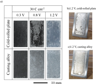
Figure 2. (a) Photographs of the Al–5.0%Cu cold-rolled plate and casting alloy obtained after the constant potential electrolysis in the EmIm–AlCl3 ionic liquid at potentials of 0.3, 0.8, and 1.2 V, a charge density of 30 C cm−2, and a temperature of 323 K. Oblique views of the (b) cold-rolled plate and (c) casting alloys obtained after the electrolysis at 1.2 V.
Download figure:
Standard image High-resolution imageThe XRD patterns of the Al–5.0%Cu cold-rolled plate and casting alloy recorded before and after the constant potential electrolysis are shown in Figs. 3a and 3b, respectively. Before electrolysis, the patterns consistent with the presence of Al and Al2Cu species were observed. The patterns of the cold-rolled plate changed very little after the constant potential electrolysis. In the patterns of the casting alloy, the peak intensities of the Al2Cu (110) and (220) planes increased significantly at 0.3 V and slightly at 0.8 V. After the electrolysis at 1.2 V, the peak intensity of the (100) plane remained unchanged, and the peak of the (220) plane disappeared.

Figure 3. XRD patterns of the (a) Al–5.0%Cu cold-rolled plate and (b) casting alloy recorded before and after the constant potential electrolysis in the EmIm–AlCl3 ionic liquid at potentials of 0.3, 0.8, and 1.2 V, a charge density of 30 C cm−2, and a temperature of 323 K.
Download figure:
Standard image High-resolution imageThe FE–SEM images of the specimen surfaces obtained after the constant potential electrolysis are shown in Fig. 4. After the electrolysis of the cold-rolled plate conducted at 0.3 V, particles with sizes of several micrometers were formed in the surface hole area, and at an electrolysis potential 0.8 V, fine particles were unevenly distributed on the plate surface in the form of islands. According to the EDS data, these particles consisted of Al and Cu atoms. At a potential of 0.8 V, they dissolved to form uneven surfaces, while at 1.2 V, the surface was more even than that at 0.8 V. At a potential of 0.3 V, a coarse mesh-like structure was formed on the casting alloy surface. At 0.8 V, a mesh-like structure was also detected, but a part of that structure was dissolved, and a flat surface was produced at a potential of 1.2 V.

Figure 4. FE–SEM images of the Al–5.0%Cu (a)cold-rolled plates and (b) casting alloy surfaces obtained after the constant potential electrolysis in the EmIm–AlCl3 ionic liquid at potentials of 0.3, 0.8, and 1.2 V, a charge density of 30 C cm−2, and a temperature of 323 K.
Download figure:
Standard image High-resolution imageThe FE–SEM images and Cu EDS profiles of the specimen cross-sections obtained after the constant potential electrolysis are shown in Fig. 5. For the cold-rolled plate, many particles with sizes of several micrometers were produced on the samples surfaces at 0.3 V (marked by ϒ in the FE–SEM images), which contained Cu atoms according to the EDS results. At a potential of 0.8 V, a dense film was formed on the particle surface, and Cu atoms were detected in both the film and particles via EDS. This dense film corresponding to the black area in Fig. 2 was not observed at 1.2 V. At a potential of 0.3 V, a coarse structure appeared on the casting alloy surface. At 0.8 and 1.2 V, coarse structures were also formed on the specimen surfaces; however, they were partially dissolved, as shown in the magnified SEM images (marked by ϒ in the FE–SEM images).
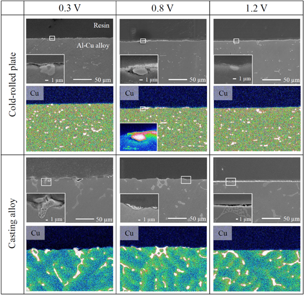
Figure 5. FE–SEM images of the Al–5.0%Cu cold-rolled plate and casting alloy cross-sections and the corresponding EDS profiles of Cu element obtained after the constant potential electrolysis in the EmIm–AlCl3 ionic liquid at potentials of 0.3, 0.8, and 1.2 V, a charge density of 30 C cm−2, and a temperature of 323 K.
Download figure:
Standard image High-resolution imageThe magnified FE–SEM images and Cu EDS profiles of the specimen cross-sections for the Al–5.0%Cu cold-rolled plate obtained after the constant potential electrolysis at 0.8 V are shown in Fig. 6. A dense film was observed on the surface layer over a wide area. Cu was detected in this film via EDS (Figs. 6a–6c). The EDS Al and Cu profiles of the film cross-section for the Al–5.0%Cu cold-rolled plate are shown in Fig. 7. In the bulk, mainly Al was detected, whereas, in the intermetallic compound, Al and Cu were detected in an atomic ratio of approximately Al:Cu = 2:1. In the film, slightly more Cu than Al was observed.

Figure 6. Magnified FE–SEM images of the Al–5.0%Cu cold-rolled plate cross-section and the corresponding Cu EDS mappings obtained after the constant potential electrolysis in the EmIm–AlCl3 ionic liquid at a potential of 0.8 V, charge density of 30 C cm−2, and temperature of 323 K.
Download figure:
Standard image High-resolution image
Figure 7. The EDS Al and Cu profiles of the film cross-section of the Al–5.0%Cu cold-rolled plate obtained after the constant potential electrolysis in the EmIm–AlCl3 ionic liquid at a potential of 0.8 V, charge density of 30 C cm−2, and temperature of 323 K.
Download figure:
Standard image High-resolution imageNext, the anodic dissolution and cathodic electrodeposition behavior of the Al–5.0%Cu alloys were investigated at various potentials. Figure 8 shows the photographs of the Al–Cu anode and Ti cathode obtained after the constant potential electrolysis of Al-5.0%Cu cold-rolled plates and casting alloys at 0.3, 0.8, and 1.2 V, and an electric charge density of 100 C cm−2. At a potential of 0.3 V, the surfaces of the cold-rolled plate and casting alloy became dark; at 0.8 V, they became dark immediately after electrolysis, but the dark layer was washed away by rinsing. After the electrolysis at 1.2 V, the surfaces of the cold-rolled plate and casting alloy became shinier than they were before the electrolysis. Dendritic electrodeposits were observed on the cathode for all potentials.
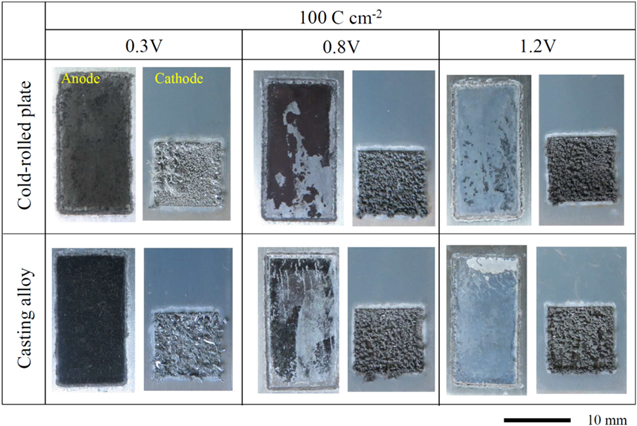
Figure 8. Photographs of the Al–5.0%Cu cold-rolled plate and casting alloy anodes and Ti cathode obtained after the constant potential electrolysis in the EmIm–AlCl3 ionic liquid at potentials of 0.3, 0.8, and 1.2 V, a charge density of 100 C cm−2, and a temperature of 323 K.
Download figure:
Standard image High-resolution imageThe FE–SEM images and Cu EDS profiles of the anode specimen surfaces obtained before and after the constant potential electrolysis are shown in Figs. 9 and 10. For the cold-rolled plates (Fig. 9), numerous unevenly distributed particles with sizes of several micrometers to several tens of micrometers were observed over a wide area on the specimen surface at 0.3 V; these particles contained Cu atoms, according to the EDS results. At 0.8 V, a microscopically uneven surface was formed; Al and Cu atoms were detected over the whole surface. At 1.2 V, a more even surface than that at 0.8 V was formed, and Cu atoms were distributed similarly as before the electrolysis. For the casting alloys (Fig. 10), a Cu-containing coarse structure was observed on the specimen surface at 0.3 V. A coarse structure containing Cu was observed even at 0.8 V; however, it was more even than that at 0.3 V. At 1.2 V, a more even surface than that at 0.8 V was formed, and Cu atoms were distributed similarly as before electrolysis.

Figure 9. FE–SEM images of the Al–5.0%Cu cold-rolled plate surface and the corresponding Cu EDS mappings obtained before and after the constant potential electrolysis in the EmIm–AlCl3 ionic liquid at potentials of 0.3, 0.8 V, and 1.2 V, a charge density of 100 C cm−2, and a temperature of 323 K.
Download figure:
Standard image High-resolution image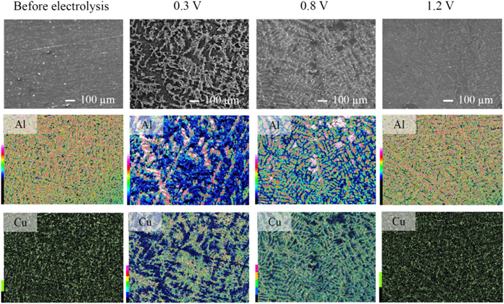
Figure 10. FE–SEM images of the Al–5.0%Cu casting alloy surface and the corresponding Cu EDS mappings obtained before and after the constant potential electrolysis in the EmIm–AlCl3 ionic liquid at potentials of 0.3, 0.8 V, and 1.2 V, a charge density of 100 C cm−2, and a temperature of 323 K.
Download figure:
Standard image High-resolution imageThe Cu concentrations of the anode surfaces and cathode electrodeposits before and after the constant potential electrolysis are shown in Fig. 11. The Cu concentration was calculated considering the sum of Al and Cu detected by EDS as 100 mass%. That is, 100% minus the concentration of Cu was taken as the purity of Al. The anode surface was analyzed via EDS at three points, and the Cu concentration was considered as the average value of these points. At 0.3 and 1.2 V, the analyses were performed at arbitrary points; at 0.8 V, the analyses were performed over the black area observed in Fig. 8. The cathode electrodeposits were analyzed via EDS at five arbitrary points, and the Cu concentration was considered as the average value of the five points. For the cold-rolled plates (Fig. 11a), the Cu concentration on the anode surface at 0.3 V was higher than that before the electrolysis, and Cu was not detected in the electrodeposit; at 0.8 V, the Cu concentration on the anode surface was higher than that at 0.3 V, and a Cu concentration of 1.9% was measured in the electrodeposit; at 1.2 V, the Cu concentration on the anode surface was similar to that before the electrolysis, and a Cu concentration of 4.6% was measured in the electrodeposit. For the casting alloys (Fig. 11b), the Cu concentration on the anode surface at 0.3 V was higher than that before the electrolysis, and Cu was not detected in the electrodeposit; at 0.8 V, the Cu concentration on the anode surface was lower than that at 0.3 V, and a Cu concentration of 2.5% was measured in the electrodeposit; at 1.2 V, the Cu concentration on the anode surface was the same as that before the electrolysis, and a Cu concentration of 6.7% was measured in the electrodeposit.

Figure 11. Cu concentrations of the Al-5.0%Cu (a) cold-rolled plate and (b) casting alloy anode surfaces and Cu concentrations and Al purity of the corresponding cathode electrodeposits before and after the constant potential electrolysis in the EmIm–AlCl3 ionic liquid at potentials of 0.3, 0.8 V, and 1.2 V, a charge density of 100 C cm−2, and a temperature of 323 K, measured via EDS.
Download figure:
Standard image High-resolution imageDiscussion
The anodic polarization behaviors of the Al–1.0 and 3.0%Cu casting alloys and cold-rolled plates illustrated in Fig. 1 are consistent with a typical dissolution behavior of pure Al in EmImCl-AlCl3 ionic liquids. 18,19 In addition, the anodic polarization curves of the Al–1.0, 3.0, and 5.0%Cu casting alloys and Al–5.0%Cu cold-rolled plates exhibited peak currents at approximately 0.8 V. The peak currents at 0.8 V were different with the anodic dissolution of Cu. 17,20 The cross-sectional microstructures of these Al–Cu alloys contained dark areas with sizes ranging from a few to several tens of micrometers, and the results of SEM–EDS analysis of the Al–5.0%Cu surface obtained before electrolysis (Figs. 8 and 9) also revealed the presence of particles with Cu contents varying between several micrometers to several tens of micrometers. The dark areas of the cross-sectional structures presented in Fig. 1 and particles depicted in Figs. 8 and 9 had similar sizes and morphologies. Therefore, both regions were considered identical. The XRD diffraction pattern of Al–5.0%Cu displayed in Fig. 3 shows the presence of Al2Cu intermetallic compound. From these results, it can be concluded that the Al2Cu phase in the casting alloy is an intermetallic compound that solidified from the liquid phase during casting, while the Al2Cu species present in the cold-rolled plate may be an intermetallic compound that was broken into smaller pieces during rolling or precipitated from the Al matrix during homogenization. The peak of the current density in the anodic polarization curve observed at 0.8 V could originate from the anodic dissolution of Al2Cu.
The SEM image of the alloy surface obtained after the constant potential electrolysis (Fig. 4) shows that Al2Cu did not dissolve at 0.3 V and remained on the surface, while the Al species from the matrix phase preferentially dissolved. In addition, many deep etch marks were observed on the specimen surface, which were likely caused by the physical release of Al2Cu into the solution due to the dissolution of Al in the matrix around Al2Cu particles.
The dissolution of Al2Cu was observed at higher potentials than 0.8 V, which was consistent with the anodic polarization curves. However, the sample surface dissolved at a constant potential at 1.2 V exhibited a lower roughness than that of the surface formed at 0.8 V. This suggests that Al2Cu also dissolved at 0.8 V but slower than the Al matrix phase.
When electric charge density of the dissolution increased to 100 C cm−2 from 30 C cm−2, the difference in dissolution behavior for potential was more obvious. At a potential of 0.3 V and electric charge density of 100 C cm−2, more Al2Cu was observed on the surface of the cold-rolled plate and casting alloy than that of 30 C cm−2 (Figs. 4, 9, 10). At a potential of 0.8 V with electric charge density of 100 C cm−2, some regions of the cold-rolled plate and casting alloy became dark (Fig. 8), furthermore Cu was detected by EDS in large areas of the surface (Figs. 9 and 10). It is considered that as the dissolution electric charge density increased, at a potential of 0.3 V, anodic dissolution of Al in the matrix phase was proceeded further, at a potential of 0.8 V, anodic dissolution of Al2Cu in the matrix phase was also proceeded further. At a potential of 1.2 V, no significant difference was observed between 30 C cm−2 and 100 C cm−2.
Figure 5 shows the cross-sectional images of the cold-rolled plate indicating the formation of a dense Al2Cu surface layer after the constant potential electrolysis at 0.8 V. At this potential, the dissolution of Al and Al2Cu species in the matrix phase occurred; however, because the dissolution of Al2Cu in the surface layer was slower than that of the matrix phase, the relative Al2Cu fraction on the surface increased during dissolution. Therefore, fine Al2Cu particles were formed on the specimen surface as a dense concentrated layer.
As the dissolution electric charge density increased (Fig. 11), a higher Cu concentration was measured at 0.8 V than at 0.3 V for the cold-rolled plate, whereas a higher Cu concentration was measured at 0.3 V than at 0.8 V for the casting alloy. Cold-rolled plates contain dispersed Al2Cu with small grain sizes. Therefore, at 0.3 V, as only the Al of the matrix phase is dissolved, the surroundings of the Al2Cu dissolve; it is considered that some of the Al2Cu is desorbed from the anode surface during the electrolysis and rinsing process after electrolysis. Additionally, Al2Cu is also slightly dissolved at 0.8 V. As previously mentioned, the concentrated layer that was not dissolved was dense; thus, the Cu concentration is considered to be high in the concentrated layer. The casting alloys contain a coarse metallurgical structure of Al2Cu. Therefore, at 0.3 V, the desorption during the electrolysis and rinsing is considered to occur to a lower extent for the casting alloy than for the cold-rolled plate. Because of the large number of gaps in this microstructure, after the electrolysis at 0.8 V, it is considered that a dense enriched layer was not formed, which led to the Cu concentration measured at 0.3 V being higher than that at 0.8 V. At 1.2 V, the Al and Al2Cu in the matrix phase were forced to dissolve at similar rates, and thus, a smooth surface (similar to that before electrolysis) was maintained. A schematic diagram of the anodic dissolution behavior of the Al–Cu alloys, as described above, is shown in Fig. 12.

Figure 12. Schematic diagrams of the anodic dissolution for (a) the cold-rolled plate and (b) casting alloy anodes in the EmIm-AlCl3 ionic liquid.
Download figure:
Standard image High-resolution image
Figure 11 shows that Cu was not detected in the cathodic deposit at 0.3 V, but it was detected in the deposits at 0.8 V and 1.2 V. This is considered to be due to the dissolution of Al2Cu at potentials above 0.8 V. It is considered that the Cu derived from the dissolved Al2Cu from the anode co-deposited with Al at the cathode. As previously mentioned, Al2Cu dissolves faster at 1.2 V than at 0.8 V. Therefore, higher amounts of dissolved Cu ions were electrodeposited on the cathode at 1.2 V than at 0.8 V.
In summary, the potential dependence of the anodic dissolution behavior of the Al−Cu alloys in the EmImCl–AlCl3 ionic liquid was examined in this study. By controlling the anodic dissolution potential, the dissolution of Cu in Al2Cu into the electrolyte can be suppressed, thus considerably increasing the purity of electrorefined Al.
Conclusions
The anodic dissolution behavior of the Al–Cu alloys in the EmImCl–AlCl3 ionic liquid with a molar ratio of 1:2 was investigated in this work. The obtained results are summarized as follows:
- The Al–Cu alloys containing Al2Cu surface species exhibit a peak anodic current density at 0.8 V during anodic polarization.
- During the constant potential electrolysis of the Al–5.0%Cu casting alloy and cold-rolled plate, the Al atoms of the matrix phase preferentially dissolved at 0.3 V, and a larger Al2Cu amount was observed on the specimen surface. In contrast, both the Al and Al2Cu species of the matrix phase dissolved at electrolysis potentials of 0.8 and 1.2 V. The SEM–EDS analysis of the specimen surface conducted after the constant potential electrolysis revealed that the dissolution of Al2Cu proceeded slower than the dissolution of Al atoms from the alloy matrix at 0.8 V.
- The Al–5.0%Cu cold-rolled plate electrolyzed at 0.8 V formed a dense surface layer enriched with Al2Cu particles because Al2Cu was less soluble than the matrix Al. The increase in the electric charge density promoted the Al dissolution from the matrix and diffusion of Al2Cu particles from the alloy bulk to the surface.
- Cu was co-deposited on the cathode at the potentials at which Al2Cu dissolved.
By controlling the anodic dissolution potential, the dissolution of Cu in Al2Cu into the electrolyte can be suppressed, thus considerably increasing the purity of electrorefined Al.
Acknowledgments
This work was partially supported by the New Energy and Industrial Technology Development Organization (NEDO). We would like to express our gratitude to all parties concerned.