

Abstract
This study investigates corrosion of Fe–(Cr)–Ni model alloys in eutectic molten chloride salt mixtures that broadly simulate the heat transfer circuits of molten salt cooled nuclear reactors. The primary focus is impurity-driven corrosion and selective dissolution of electrochemically reactive element(s) (dealloying), which are known degradation modes for Fe– and Ni-based alloys in molten salts. This study demonstrates that a Mg rod performs close to a true Mg∣Mg2+ reference electrode system in a MgCl2 containing mixture. Mg dynamic reference electrodes validated the performance of the ordinary Mg reference electrode. The residual moisture content in molten salts is measured by cathodic polarization of Pt, which showed that convection of molten salts, after step-wise heating, through a bundle of Mg ribbons dropped the moisture content by 30-fold. The effect of impurities in the molten salt mixture, moisture and NiCl2, on dealloying was also investigated at low homologous temperature. It was found that the universal parting limit for dealloying is decreased to a value of approximately 32 at% Fe when Ni from the parent alloy is close to equilibrium with Ni2+ ions added to the eutectic molten salts. Results support the percolation/surface diffusion concept for dealloying in molten salts at low homologous temperature.
Export citation and abstract BibTeX RIS
Over the past decade there has been a resurging interest in the use of molten chloride salts as heat transfer media for the secondary heat transfer circuit of advanced nuclear reactors, and for solar applications. Chloride salts are cost-friendly, offer higher operating temperature than nitrate salts, have low vapour pressure, and are chemically stable at elevated temperatures. However, a key disadvantage of molten halide salts is their highly corrosive behaviour which leads to the degradation of structural materials, 1,2 such as Fe- and Ni-based alloys.
Formation of a passive oxide film (e.g., chromia) is challenging in molten Cl salts, 2–4 and a pre-formed oxide layer dissolves readily in such media. 5,6 It is widely known that impurity driven corrosion 7,8 and preferential electrolytic dissolution (dealloying) of reactive elements (e.g. Fe, Cr) from Ni- and Fe-based alloys are important challenges for the development of structural alloys for molten salt applications.
Corrosion and dealloying in molten salts can be mitigated by developing advanced alloys, applying coatings, and salt purification. Pure halide salts based on K, Na, Li and/or Mg are not corrosive to Ni- and Fe-based alloys because there is no cathodic reaction. 9,10 Thus, it is generally accepted that oxidizing impurities in molten Cl salts are responsible for driving corrosion. 1,2
Measurement of Corrosive Impurities in Molten Salts
Impurities in molten Cl salts include: H2O and O2; secondary products of chemical reactions, HCl, Cl2, H+, OH−; hydroxides, and oxychlorides; metal halides (e.g., CrCl3, FeCl3, NiCl2) that are corrosive towards metals with lower standard potential. 2,7,11 Salts are hygroscopic in nature, and when hydrolyzed (especially Mg salts), they form metal hydroxides, oxychlorides, oxides, and HCl. 11 Thus, molten salts must be purified to remove impurities, in particular water.
Initial dehydration through a step-wise heat treatment is often applied, 12,13 but remnant moisture results in the formation of oxychlorides and highly soluble and corrosive HCl. Addition of a soluble salt redox buffer is sometimes used to control the redox potential in molten salts. 10 One way to remove moisture is the addition of Mg metal 14 and/or a Mg–Cd alloy 15 to molten Cl salts. Other methods to remove moisture include: carbochlorination, 16 use of NH4Cl, 16 and sparging Ar gas through liquid thionyl chloride and placing it in contact with the heated salt (below melting point). 17
Measurement of impurities in molten salts has become a priority to limit material degradation. Some options are not practical in terms of application, including: collection of oxygen released by fluorination of oxides by addition of halogen fluorides (KBrF4), 18,19 or combustion analysis to measure oxygen and hydrogen impurities. 20 Electrochemical methods for measuring impurity concentration are promising. Several reference electrode systems have been developed for molten Cl salt systems, such as Cl−∣Cl2, Li∣Li+, Ag∣Ag+, Al∣Al3+21 ; Pt acts as a quasi-reference electrode Pt/PtOx/O2− in molten salt systems. 22,23 However, the stability of these reference electrodes is sometimes questionable 24 and electrochemical corrosion studies, in particular fundamental dealloying studies, are still limited.
Development of a reference electrode system with high stability, mechanical resistance and accuracy in molten salt environments is needed to perform reliable electrochemical measurements. Such developmental work would also enable more controlled molten salt corrosion studies, including determining mechanisms for dealloying, which has not yet been studied at a sufficiently fundamental level.
Molten Salt Dealloying
In molten halide salt corrosion, at relatively high homologous temperature (TH), where lattice diffusion is relevant, Fe- and Ni-alloys are known to undergo intergranular corrosion 5,25 and selective dissolution of reactive elements (dealloying). Dealloying in molten salts is discussed in terms of one-dimensional diffusion of a dissolving reactive element from the bulk of the alloy to the surface. 26 Dealloying of Cr in alloys exposed to molten chloride salts is a common example. 27
Dealloying is the selective electrolytic dissolution of less-noble (LN) element(s) from a homogenous alloy, 28 at low homologous temperature it result in porous structure rich in the more-noble (MN) metal. 29 The difference in standard metal/metal-ion electrode potentials of the LN and MN elements is the driving force for dissolution of the LN element. The operative mass transport process in aqueous dealloying is diffusion of the MN element at the solid/electrolyte interface. 28
The parting limit for dealloying is the minimum content of the LN element(s) below which macroscopic dealloying does not occur, the usual threshold is ca. 55–60 at% of the LN element(s) in classical systems. 28 Continuous selective dissolution of LN metal(s) above the parting limit is known to occur above a critical potential, 30,31 dependent on the atom fraction of the MN metal in the parent alloy.
A recent study by authors 32 revealed that fcc alloys undergo classical dealloying with porosity formation in molten salts at low homologous temperature (350 °C ∼ TH = 0.36), similar to aqueous systems but with coarser ligament size. An interconnected, microporous Ni-rich layer evolves upon selective electrolytic dissolution of Fe and Cr in Fe–Ni and Fe–Cr–Ni model alloys when exposed to molten salts, and it was demonstrated that dealloying in molten salts is in-line with percolation dissolution theory. 33,34 In other words, similar to aqueous systems, the operative mass transport mechanism for molten salt dealloying is mediated by the surface diffusion of the MN element, Ni, at the alloy/molten salt interface at low homologous temperature.
The parting limit for dealloying Fe–(Cr)–Ni is usually quoted as ca. 55–60 at% of the LN element(s) (Fe/Fe+Cr) for systems at moderate temperatures 28 and even in caustic solutions at 280 °C dealloying diminished when content of LN element(s) was 52 at% 32 showing that an increase in surface diffusivity can lower the parting limit slightly, as already understood. According to Artymowicz et al., 34 the dealloying threshold could be shifted downward by increasing the kinetics of surface diffusion of the MN metal at the solid/electrolyte interface. In the previous study by authors, 32 it was shown that the parting limit at low homologous temperature (350 °C ∼ TH = 0.36) is decreased to 44 at%., compared with aqueous systems, due to the very fast interfacial diffusion of Ni which is in agreement with the study of Artymowicz et al. 34 Such a shift in parting limit due to enhanced surface diffusion of Ni, with use of developed true reference electrodes for molten Cl salt systems, is the focus of this work.
In the molten salt corrosion studies, the effect of addition of salt of alloying elements to the eutectic mixture has mostly been studied in fluoride salts; addition of FeF2 and CrF3 increase the rate for selective dissolution of Cr. 35,36 In molten chloride salt systems, it is reported that addition of FeCl3 and CrCl3 to the mixture increase the corrosion rate in Fe–Cr–Ni alloys. 2,37 However, the effect of a salt of the MN alloying element, such as NiCl2, on dealloying of Fe–(Cr)–Ni alloys in molten Cl salts has not been explored. In aqueous systems, the parting limit for dealloying falls to the fcc site percolation threshold of 20 at% 38 for dezincification in Zn–Cu alloys in neutral chloride solutions, as the elemental Cu in the brass is nearly in equilibrium with its ions; 28,39 the addition of Ni ions to molten salt mixtures may have a similar effect on reducing the parting limit.
In this study, the effect of NiCl2 addition to molten Cl salts on the corrosion of Fe–(Cr)–Ni alloys is explored, with emphasis placed on determining the mechanism of dealloying; in addition, the effect on the parting limit will be examined. In-situ purification methods for molten chloride salts are also studied, including a method for in situ measurement of concentration of impurities (i.e., remnant moisture), and development of reference electrode for molten chloride salt system for measuring impurities and studying corrosion phenomena in molten Cl salts. Using developed methods, the effect of moisture content on dealloying of Fe–(Cr)–Ni model alloys in molten Cl salts is studied, including the resulting surface morphology and the effect of composition.
Experimental Methods
Model alloy fabrication and sample preparation
Homogeneous solid solution Fe1−xNix and Fe0.78−xCr0.22Nix model alloys (x = 30–68 at%) were prepared in an Arcast Cold Crucible Induction Levitation Melter using 99.95% purity Fe and Cr, and 99.995% purity Ni, in high purity Ar gas.
Flat specimens were milled from a cylindrical ingot produced by the melter and cut to a size of 20 mm × 6 mm × 2 mm. The working electrodes were cut into a flag shape (the cross-section of the electrode-pole was 1 mm × 2 mm) to minimize the change in the active surface area of the working electrodes immersed in the molten Cl salt mixture. The accurate active surface area was also measured after the high temperature molten salt corrosion experiments to ensure consistency.
Flag shaped specimens were first abraded with 320 grit SiC paper. Heat treatment of samples was carried out in a horizontal tube furnace. Samples were annealed in flowing 2.5% H2 + Ar (bal.) gas at 1050 °C for 1 h and furnace-cooled to room temperature in the Ar-2.5%H2 atmosphere. After annealing, samples were abraded using 320 grit SiC paper (> 200 μm on each side) to remove surface oxides and any metallic depleted zones that may form due to the presence of residual water vapour during the annealing process. Following this, samples were abraded sequentially using 600, 800, and 1200 grit SiC papers, following the ASTM G61 standard.
After corrosion experiments, each sample was immediately immersed in boiling deionized (DI) water for 5 min while stirring; this was done to remove water-soluble corrosion products from any porous structure that was present. The samples were then rinsed in ethanol, dried immediately with N2 gas, and kept in a desiccator. For cross-sectional analysis, samples of interest were mounted in epoxy resin under vacuum. Samples mounted in epoxy were sequentially abraded with 320, 600, 800, and 1200 grit SiC papers, followed by polishing with 9 μm, 3 μm, and 1 μm diamond suspensions (supplied by Buehler). To remove any surface deformation caused by mechanical polishing, a final polishing step was performed using a 0.05 μm alumina polishing suspension.
Molten salt preparation
Lithium chloride, LiCl, potassium chloride, KCl, and anhydrous magnesium chloride, MgCl2, were purchased from Sigma Aldrich and were ACS grade. Each batch of salt was from the same batch of procured salt to avoid variations from changes in trace impurity content. Anhydrous nickel chloride, NiCl2, was also purchased from Sigma Aldrich for a particular experiment. A eutectic mixture of LiCl, KCl and MgCl2 salts with a composition of 55–40–5 mole %, respectively, was used for most experiments; a eutectic LiCl-KCl (60–40 mole %) mixture was used for one experiment (see the Electrochemical conditions section). The LiCl-KCl-MgCl2 eutectic has a melting point of 323 °C, and has been proposed as an ideal candidate for the secondary loop in MSRs. 40,41 The eutectic salt was prepared using a mortar, and 150 g of the mixture was used for each corrosion study.
As mentioned, chloride salts contain minor moisture content due to their hygroscopic nature, LiCl and especially MgCl2 tend to form hydroxides and oxychloride, respectively, and hydrogen chloride during heating. In order to dry the salt and eliminate hydrolysis products, 12,13 a stepwise thermal treatment was applied under vacuum at 117 °C, 145 °C, 190 °C, 227 °C, 300 °C, and 350 °C with a dwell time of 4 h, 2 h, 1 h, 1 h, 1 h, and 1 h, respectively. During each step, a glass tube was used to continuously pass Ar gas through the dry salt and through fused salts in the test crucible to reduce their water content prior to corrosion experiments. Finally, in some experiments, the molten salt mixture was convected through a bundle of Mg ribbon with very high surface area (3 cm2 of Mg per mL of molten salt) to remove H2O and HCl.
Molten salt electrochemical cell
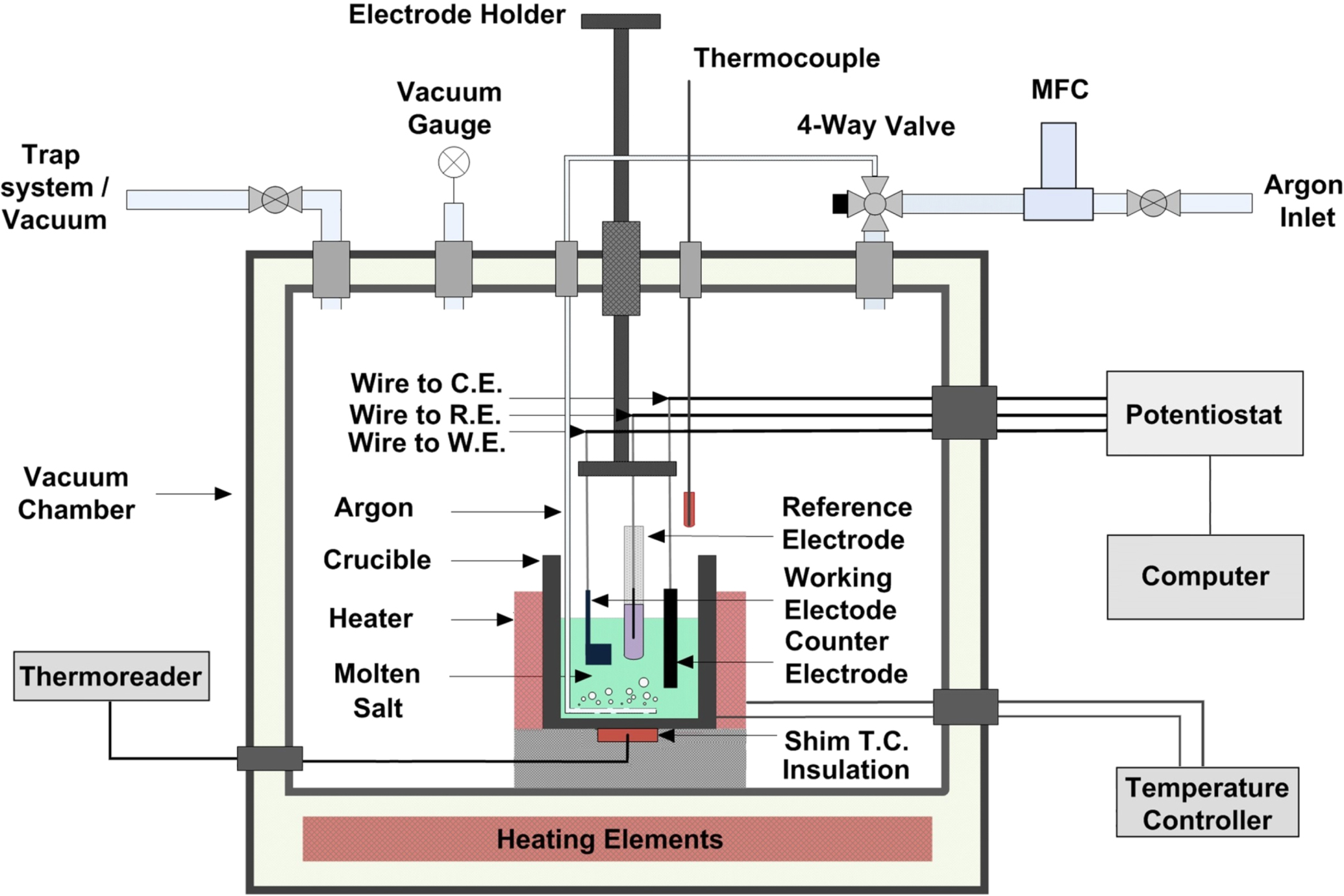
Electrochemical experiments were conducted in a three-electrode cell in a glovebox environment, operating at atmospheric pressure, or vacuum when required. A schematic of the electrochemical cell and glovebox setup is given in Fig. 1. The Ni test crucible containing the eutectic molten Cl salt electrolyte was equipped with a band heater and the cell was heated in a furnace with the temperature measured using a chromel–alumel thermocouple. Salt purification followed by electrochemical corrosion experiments were conducted inside of the glovebox environment. The glovebox was filled with circulating Ar gas to maintain an inert atmosphere.

Figure 1. Schematic diagram of the experimental setup for the corrosion experiments.
Download figure:
Standard image High-resolution imageA graphite rod with a 6 mm diameter was used as the counter electrode, and the reference electrodes were Mg∣Mg2+ and Ni∣Ni2+ (for some experiments), which were developed in this study. A Pt wire was used as a pseudo-reference electrode for some experiments. Mg rod in molten salt mixture containing MgCl2 behaved as a Mg∣Mg2+ reference electrode, similarly a Ni rod in mixture containing NiCl2 behaved as a Ni∣Ni2+ reference electrode. All electrodes were connected to a software controlled potentiostat (PARSTAT 2263, Princeton Applied Research). The working electrode (WE) was the sample of interest (see the Model alloy fabrication and sample preparation section). All electrochemical experiments were initiated after the working electrodes were fully immersed in the molten Cl salt mixture for at least 15 min to attain a steady state. As mentioned, the working electrodes were manufactured into a "flag" shape to better control the active surface area and avoid any deviation in the current density, and to ensure that the wire connection remained away from the molten salt electrolyte.
Electrochemical conditions
There are several groups of experiments:
Experiment series 1: dynamic reference electrodes (DREs) of K/Li and Mg were developed by applying different pulses of cathodic current on W as the working electrode for 5 s in LiCl-KCl (60–40 mol %) and LiCl-KCl-MgCl2 (55–40–5 mol %) mixtures. A Pt wire was used as a pseudo-reference electrode for this study. The purpose of the Mg-DRE was to validate the performance of the ordinary Mg∣Mg2+ RE, as explained below. The K/Li DRE was used to ensure conformity with the literature.
Experiment series 2: a Pt plate working electrode was used to carry out cathodic polarization tests in the molten LiCl-KCl-MgCl2 salt mixture to find the limiting current density for reduction of water in the molten salt. By suitable calibration, this is used to estimate the amount of water in the salt. Cathodic polarization was also carried in a molten salt mixture containing 2.5 × 10⁻² M NiCl2 to use the limiting current density for reduction of Ni ions (with known concentration) in molten salt mixture to estimate the amount of water, using the limiting current density of water reduction. The developed Mg∣Mg2+ reference electrode was used for this study and subsequent electrochemical measurements. Its performance and stability were checked against the Mg-DRE, which is always accurate (but short-lived), as it has a fresh metallic Mg surface.
Experiment series 3: Electrochemical corrosion studies on Fe, Cr, and Ni metals, and Fe–(Cr)–Ni model alloys were conducted in the eutectic molten LiCl-KCl-MgCl2 (55–40–5 mol %) salt mixture at 350 °C. Open circuit potential (OCP) measurements were recorded to confirm a stable potential prior to performing cyclic polarization.
Experiment series 4: Electrochemical dealloying of Fe–(Cr)–Ni model alloys was conducted in the static eutectic LiCl-KCl-MgCl2 (55–40–5 mol %) mixture at 350 °C. OCP measurements were recorded to confirm a stable potential prior to potentiostatic dealloying. Dealloying experiments were also carried out at OCP for 72 h. The effect of different moisture content on dealloying was also studied.
Experiment series 5: Anhydrous NiCl2 was introduced into the purified LiCl-KCl-MgCl2 (55–40–5 mol %) mixture in the form of powder. Dealloying experiments were carried out at different concentrations of NiCl2 to evaluate the effect on dealloying and the resulting surface layer morphology. A Ni rod behaved as a true Ni∣Ni2+ reference electrode in this particular study.
Characterization techniques
Prior to experiments, compositional and microstructural analysis were done on alloys to ensure chemical homogeneity and that no secondary phases were present. This was performed using a FEI Quanta 250 FEG Environmental Scanning Electron Microscope (ESEM) equipped with Energy-Dispersive X-ray (EDX) spectroscopy (at an accelerating voltage of 20 kV). After corrosion experiments, samples were examined using secondary electron (SE) imaging and EDX elemental analysis. Surface and cross-section analysis were performed to evaluate the occurrence of dealloying, and the morphology and composition of any porous structure, including identifying the presence or not of any core–shell ligament structure. A JEOL (JXA-8230) Electron Probe Microanalyzer (EPMA) equipped with 5 wavelength dispersive spectroscopy (WDS) X-ray spectrometers was used to measure the elemental distribution of some corroded specimens and produce WDS elemental maps; the probe current was 20 nA and accelerating voltage was 15 kV.
Results and Discussion
Reference electrode development
The stability of REs in molten salt systems is a major issue; electrodes with known and reproducible potentials are limited, and a secondary challenge is the containment of RE construction materials in molten salts. 10 In chloride salts, Bockris et al. developed 42 a Ag∣AgCl RE with a glass membrane. While glass membrane is good for low temperature application these REs face challenges with encasing materials and potential drift has often been observed. 21 Gao et al. 43 developed a quartz sealed Ag∣AgCl RE; however, the quartz encasement can only be used at temperatures above 750 °C (due to very poor ionic conductivity below this temperature) and undergoes erosion in molten Cl salts. A Li∣Li+ RE has been achieved by immersion of Li-58Al and Li-41Sb alloys in LiCl-KCl 21 ; however, the behaviour of the alloy electrode is very dependent on temperature. Pt acts as a quasi-RE and is applied in many studies. 44 Due to the sensitivity of electrochemical potential measurements in molten salts, the quasi-Pt RE is not appropriate for fundamental studies due to its sensitivity to water and the O2− impurity in the salt. 45
In this section, we outline development work performed to develop dynamic and true reference electrodes which can be applied more reliably in molten Cl salt mixtures.
Development of dynamic reference electrodes
A Pt quasi-reference electrode with the potential calibrated using the dynamic reference electrode (DRE) method has been used as a reliable reference electrode for redox potential measurements for a short term in molten fluoride salts. 45–50 A DRE is based on the in situ generation of a transient reversible redox system by applying a large pulse of cathodic current on a solid inert electrode and determining the equilibrium potential corresponding to the cathodic limit of the molten salt. 50 The purpose is to associate the potential of the quasi-RE to a thermodynamic reference. 10
In this study, DREs were created in LiCl-KCl and LiCl-KCl-MgCl2 mixtures at 400 °C. A 5 s cathodic current pulse of 5 mA, 50 mA, 100 mA, 200 mA was applied between W electrodes as WE and a graphite counter electrode to form a thin metallic layer on the W surface, i.e., reduction of K/Li or Mg ions from mixtures of LiCl-KCl and LiCl-KCl-MgCl2, respectively. The RE used to record these voltammograms was a Pt quasi-RE and the electrochemical potential of the W electrode against the Pt reference electrode was monitored with time. A pulse current of 5 s for the reduction of salt constituents was chosen to prevent the modification of the salt composition and/or high Cl2 evolution on the anodic side of the electrolysis (on the graphite). To limit the influence of other metallic impurities co-deposited during the current pulse, the only parameter for DRE generation is the variation of intensity of the cathodic current pulse applied. Figures 2 and 3 correspond to generation of DREs in LiCl-KCl and LiCl-KCl-MgCl2 mixtures, respectively. In these chronopotentiograms, zone I is the OCP of W vs Pt before the applied cathodic current, zone II corresponds to the potential measurement with an applied current on W, zone III is related to the monitoring of potential once the cathodic current pulse is turned off, and zone IV is measurement of the decay of potential until returning to the initial value, OCP.

Figure 2. Chronopotentiograms showing the potential evolution of the W working electrode against the Pt RE over time. Experiments were carried out as follows: 10 s at OCP, followed by an applied cathodic current pulse of (1) 5 mA, (2) 50 mA, (3) 100 mA, and (4) 200 mA for 5 s in molten LiCl-KCl at 400 °C.
Download figure:
Standard image High-resolution image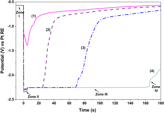
Figure 3. Chronopotentiograms showing the potential evolution of the W working electrode against the Pt RE over time. Experiments were carried out as follows: 10 s of OCP, followed by applied cathodic current pulse of (1) 5 mA, (2) 50 mA, (3) 100 mA, and (4) 200 mA for 5 s in molten LiCl-KCl-MgCl2 at 400 °C.
Download figure:
Standard image High-resolution imageBy applying cathodic currents, a thin layer of metallic K/Li or Mg is being electrodeposited at the surface of the W electrode in LiCl-KCl and LiCl-KCl-MgCl2 systems, respectively; basically, K/Li, and Mg ions can be electrodeposited on a W WE and DREs are achieved in which the redox potential of K,Li∣K+,Li+ and Mg∣Mg2+ can be captured as shown in Figs. 2 and 3, respectively. The reference redox systems generated by coulometry at an applied current are K,Li∣K+,Li+ and Mg∣Mg2+ in LiCl-KCl and LiCl-KCl-MgCl2, respectively. Results show that a higher current pulse resulted in slightly lower value for the potential of K,Li∣K+,Li+ and Mg∣Mg2+ in zone II. As seen in Fig. 2, when the applied current pulse is low, the deposits rapidly oxidize and the potential varies from the K,Li∣K+,Li+ and Mg∣Mg2+ redox systems towards the open circuit potential of the W, as seen in zone IV of Figs. 2 and 3.
Results in Figs. 2 and 3 also confirm that the 5 s pulsing time is optimal, as described elsewhere, 50 noting that the DRE's performance depends on the electrodeposition time and the intensity of the applied current. Results also indicate that a small pulse current magnitude is insufficient for reduction of K+/Li+ and Mg2+ ions to form a fully covered K/Li and Mg layer on the W electrode. When the intensity of the cathodic current is large enough (200 mA), the redox potential of the DRE tends to a constant and stable value. This indicates that the metallic deposition is constituted of K/Li in the LiCl-KCl and Mg in the LiCl-KCl-MgCl2 mixture, and the potential is not influenced by small quantities of other remnant impurities that simultaneously may be reduced.
In zone III, the potential steps up and stabilizes at a slightly higher value once the current pulse is turned off. This potential corresponds to the equilibrium potential of K,Li∣K+,Li+ and Mg∣Mg2+, and will remain constant for a certain time. The resulting equilibrium potentials of K,Li∣K+,Li+ and Mg∣Mg2+ vs Pt RE are −3 V and −2.25 V, respectively. The Mg-DRE is stable up to 3 min upon a cathodic pulse of 200 mA for 5 s. This temporal condition ensures that the thin metallic layer is sufficiently stable for OCP measurements with high reliability and good accuracy. The measurement of the equilibrium potential of alloying elements has to be performed in zone III.
Developed DREs could be used to temporarily calibrate the potential of a Pt quasi-reference electrode and importantly validate the stability of developed true reference electrode (see the Development of true reference electrodes section). Mg-DREs, generated periodically in-situ in the molten salt mixture, will be used (at 350 °C) to confirm the stability and performance of the true Mg∣Mg2+ RE (developed in the Development of true reference electrodes section). Furthermore, the DRE potential could be measured against a metal (M) wire immersed in the molten salt of the metal chloride (MClx) to produce a redox potential series of elements vs the reduction of molten salt constituents (e.g. Mg∣Mg2+).
Development of true reference electrodes
In previous section, development of DREs was provided for the molten Cl salt system. While a DRE is useful for reporting redox potentials using a Pt RE vs DRE, their potential signal cannot be sampled for a long period of time. 10 Building upon the developed Mg-DRE, it was found that a Mg rod could be used as a Mg∣Mg2+ reference electrode when MgCl2 salt is part of the salt mixture, such as the 5 mol % used in the salt mixture for this work. It is important to highlight that the performance of this reference electrode system depends on water content in the molten salt and the concentration of Ni, Cr, and Fe ions. Water changes the surface layer of Mg to MgClOH and transition metal ions (from corrosion) reduce at the surface of the Mg electrode. Therefore, purification is a necessity.
The developed static Mg∣Mg2+ RE (Mg-SRE) was calibrated against Mg-dynamic reference electrode (Mg-DRE) to validate its stability. For this purpose, several Mg-DREs were generated in in molten LiCl-KCl-MgCl2 at 350 °C to investigate the stability of the ordinary Mg-SRE. A series of galvanostatic electrolysis were carried out on W electrodes (the procedure outlined in the Development of dynamic reference electrodes section), with duration of about 2 h, at 15 min intervals; the potential of the cathodic limit was attributed to Mg∣Mg2+. Each time the potential of the generated Mg-DREs were measured vs the conventional Mg reference electrode as shown in Fig. 4. It is found that the potential difference is stable during measurement at different time intervals and it is about −0.8 mV, as seen in Fig. 4a, when the limiting current density for water reduction is 1 × 10⁻⁴ A cm−2 (see the In-situ electrochemical measurement of impurities section). The effect of a higher water content on stability and potential difference between Mg-SRE and Mg-DRE was also investigated, and it was found to be stable at different intervals over 2 h as seen in Fig. 4b. However, the potential difference increased to −6.7 mV when the limiting current density for water reduction in molten salts was 1 × 10⁻³ A cm−2.
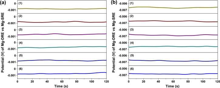
Figure 4. Potential of Mg-DREs vs ordinary Mg∣Mg2+ RE (Mg-SRE) in the eutectic LiCl–KCl–MgCl2 salt mixture at 350 °C, numbers 1–6 in each graph correspond to DRE generation with interval of 15 min. Each Mg-DRE was generated by applied cathodic current pulse of 200 mA on W WE for 5 s. (a) and (b) refer to molten salt batches with different water content in which limiting current density for water reduction is 1 × 10⁻⁴ A cm−2 and 1 × 10⁻³ A cm−2, respectively.
Download figure:
Standard image High-resolution imageFew studies 7,51 have reported formal standard potentials for Ni, Fe, and Cr vs a reliable reference electrode in molten salts. Here it is shown that OCP of these metals can be measured vs a true Mg∣Mg2+ reference electrode in LiCl-KCl-MgCl2 (55–40–5 mol %) at 350 °C. Cyclic polarization scans were obtained at a scan rate of 2 mV s−1, with replicate tests carried out to ensure consistent results. A rigorous purification procedure was carried out on the salt mixture prior to experiments (see the Molten salt preparation section).
Open circuit potential measurements for Fe, Cr, and Ni were measured vs Mg∣Mg2+, as seen in Fig. 5a; it was confirmed that the OCP of Cr is lower than Fe, and the potential of both elements is less than Ni, similar to other authors. 52 Thus, in Fe–(Cr)–Ni alloys, Cr is the most reactive element in molten Cl salts, and both Cr and Fe are expected to undergo preferential electrolytic dissolution in this medium 26,32,53–56 (see the Dealloying in molten chloride salts section). In molten Cl salts at 350 °C, the corrosion potential of Ni is about 270 mV and 470 mV more positive than Fe and Cr, respectively. Similar potential differences have been observed for the OCP of these metals in molten fluoride salts. 51
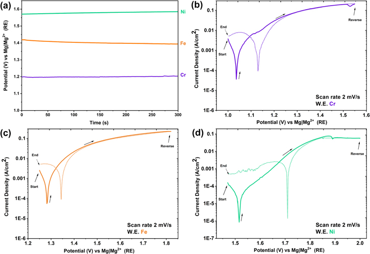
Figure 5. Open circuit potential of Cr, Fe and Ni metal (a), cyclic polarization of Cr (b), Fe (c), and Ni (d) in a eutectic molten salt mixture of LiCl-KCl-MgCl2 at 350 °C.
Download figure:
Standard image High-resolution imageFrom the cyclic polarization of Fe, Cr, and Ni metals in Fig. 5, it is observed that active dissolution takes place, as current density increases with increasing potential. At OCP, the corrosion current density of Fe is slightly lower than Cr; however, their corrosion current densities are approximately 50 times more than that of Ni. In the cyclic polarization scan for Ni, during the forward scan at an anodic potential of 1.88 V vs Mg∣Mg2+, supersaturation of Ni ions is observed, which then results in salt precipitation. Thus, this region has a minimum followed by an anodic limiting current density, this limiting current density behaviour is also visible during the reverse scan. During the reverse scan on Ni, at 1.68 V vs Mg∣Mg2+ RE, a peak in current density behaviour is observed, and it is attributed to oxide reduction, since the sample was polarized at high anodic overpotentials. At less positive potentials, diffusion limited oxygen reduction is observed on the cathodic branch of the cyclic polarization curves.
A very important observation was the confirmation that the Mg∣Mg2+ RE system showed a stable performance for potential measurements and cyclic polarization—noting that the water content was maintained at a very low level (see the In-situ electrochemical measurement of impurites section for measurement of water content). The stable performance of the Mg∣Mg2+ RE is further proven during cathodic polarization of a Pt WE in the eutectic molten LiCl-KCl-MgCl2 mixture by monitoring the potential for reduction of Mg2+ ions from the eutectic mixture and the subsequent oxidation of the plated Mg (see the In-situ electrochemical measurement of impurites section).
Similar to the development of a true Mg∣Mg2+ RE by employing a Mg rod in a mixture containing MgCl2, a true Ni∣Ni2+ RE was developed for mixtures where the effect of Ni ion addition to the molten salt on the dealloying mechanism was studied (see the effect of addition of a salt of the more noble alloying element on the parting limit section). In this case a Ni rod behaves as nearly a true Ni∣Ni2+ RE provided that NiCl2 was part of the mixture. With the addition of NiCl2, a Mg rod cannot be used as a RE for the mixture due to deposition of Ni ions on the Mg surface and deviation of potential.
In the developed reference electrode systems, encasing materials for both true Mg∣Mg2+ and Ni∣Ni2+ REs are not necessary because in their corresponding molten salt mixture both MgCl2 and NiCl2 (for the latter case) were part of the molten salt mixture. A Ni∣Ni2+ RE has also been employed previously in electrochemical studies in molten fluoride salts, but with the use of encasing materials. 35,57
In-situ electrochemical measurement of impurities
Similar to aqueous solutions, molten salt corrosion comprises a partial anodic current density (ia ) and partial cathodic current density (ic ) related to reduction of oxidants under a mixed potential, and the rates of these half reactions become equal at the corrosion potential (Ec ), corresponding to a corrosion current density (icorr ). The anodic reaction is attributed to dissolution of a metal (or a reactive alloying element if the parting limit is met) that may also form a metal oxide or a salt film. But the cathodic reaction is complicated in molten salts; major oxidants in a molten Cl salt media are O2, H+, H2O, and OH−. Thus, it is necessary to identify these reactions and estimate moisture content with respect to purification method. As mentioned, currently offline analytical techniques (such as ICP-OES/MS, XRF, NAA) are commonly used to quantify trace impurities of water, hydroxides, oxides, and ions of transition metals in molten salts. However, the ability to monitor impurities online, before or during electrochemical corrosion experiments, is still difficult.
In this section, the water impurity content was monitored electrochemically in situ; cathodic polarization experiments were performed at a low rate on a Pt plate working electrode before and after final water removal was carried out using the Mg ribbon purification method (mentioned in the Molten salt preparation section). From cathodic polarization, it is possible to understand at which potentials water reduction occurs in the molten LiCl-KCl-MgCl2 mixture. The ability to identify the limiting current density for water reduction allows for in situ monitoring of the change in concentration of water in the molten salt mixture. Thus, moisture content can be measured for different purification methods, with estimation of the water content by calibrating it to reduction of Ni ions with known concentration.
A three-electrode electrochemical cell setup was used with a Mg∣Mg2+ true reference electrode (see the Reference electrode development section). A graphite rod was used as a counter electrode. Pt plate was chosen as the working electrode as it is very catalytic towards water reduction. The electrochemical window for the Li-K-Mg Cl salt mixture is between the reduction of Mg2+ ions and the oxidation of the Pt electrode; thus, Pt plate can be considered an inert electrode. Cathodic polarization experiments were carried out on the Pt plate electrode, scanning from OCP to −2 V vs OCP with a scan rate of 3 mV s−1.
The first cathodic polarization scan was carried out in a molten Cl salt batch that was not convected through a bundle of Mg ribbon (only step wise heat treatment purification was conducted); the cyclic polarization result shown in Fig. 6a includes the following reduction reactions:
- I.On the backward scan, a limiting current density of approximately 7.5 × 10⁻⁴ A cm−2, between 1.25 V and 1.5 V vs Mg∣Mg2+, corresponds to O2 reduction via O2 + 2H2O + 4e− → 4OH−. In the literature, 7 reduction of O2 via O2 + 2e− → O2 2− and O2 2− + 2e− → 2O2− reactions is proposed, but such a reduction pathway only happens when water is not present.
- II.Continuing on the backward scan, at potentials less than 1.25 V vs Mg∣Mg2+ a limiting current density was observed and, during the experiment, was accompanied by the formation of visible gas bubbles at the Pt WE, indicating that the process is not related to decomposition. The limiting current density of approximately 3 × 10⁻³ A cm−2 between approximately 1.25 V and 0.5 V vs Mg∣Mg2+ is attributed to H2O reduction and H2 formation via 2H2O + 2e− → H2 + 2OH−.
- III.
- IV.The increasing cathodic current below approximately 0.1 V vs Mg∣Mg2+ on the reverse scan is associated with Mg metal deposition on the Pt WE.
- V.Then, the scan was reversed at −0.25 V vs Mg∣Mg2+. During the reverse scan near 0 V vs Mg∣Mg2+ the minimum in current density corresponds to the OCP of Mg. The anodic current peak at 0.25 V in the reverse scan is associated with stripping of some of the deposited Mg.

Figure 6. Cathodic polarization of Pt plate in molten LiCl-KCl-MgCl2 salts at 350 °C. (a) is a scan where salt is purified with step-wise heat treatment but without convection of molten salt through a bundle of Mg ribbons, while (b) shows the scan for purification in which molten salt is convected through a bundle of Mg ribbons after step-wise heat treatment.
Download figure:
Standard image High-resolution imageA second set of cathodic polarization experiments was carried out on Pt in the molten Cl salt mixture but under conditions where the salt was convected through a bundle of Mg ribbon with high surface area after step-wise heat treatment. This allows for confirming whether the mentioned reduction potentials from Fig. 6a are attributed to the reduction of O2, and H2O and OH−, and to elucidate the effect of a new purification method by comparing the limiting current density for reduction of H2O. As seen in the cyclic polarization graph in Fig. 6b, the limiting current density for reduction of O2 has been reduced significantly. Importantly, the limiting current density for water reduction (shown as zone II) has decreased to 6 × 10⁻⁴ A cm−2. Results reported here are consistent with recent work in literature 7 ; a potential difference of approximately 0.7 V between the reduction of H2O and OH− is observed in this study. This is similar to the potential difference for the H2 evolution of H2O and OH− reduction reactions in LiCl-KCl at 450 °C, which were reported to be −1.9 V and −2.6 V vs. Cl2∣Cl− RE, respectively. 2,59
The anodic behaviour of the deposited Mg on the reverse (forwards) potential scan, suggests a level of complexity in the Mg dissolution mechanism that occurred in replicate tests (zone V). Integration of the current time diagram for Fig. 6b indicates that not all of the deposited Mg during cathodic polarization on Pt has been dissolved. As seen in the reverse scan, there are several peaks in the Mg dissolution range of potential. Result show that when Mg is subjected to high-rate dissolution, there can be precipitation of MgCl2 on the surface or even freezing of the salt in the boundary layer leading to a double peak feature. This could also be attributed to an oxychloride which would probably be a solid at 350 °C, form and grow, then flake off. As seen in the SEM micrograph in Fig. 7 there exists a thin scale on the surface of Pt after being cathodically polarized, even though the potential has been reversed to the original starting condition, EDX analysis confirmed that there are Mg, and O containing precipitates.
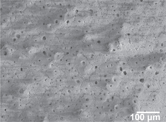
Figure 7. Surface SEM micrograph on a Pt electrode after cathodic polarization (shown in Fig. 6) in molten LiCl-KCl-MgCl2 salts at 350 °C.
Download figure:
Standard image High-resolution imageFurther cathodic polarization experiments were carried out to determine the effectiveness of convecting the molten Cl salt through Mg ribbons on reducing water content of molten salt mixture. This was performed by using a Mg ribbon bundle with very high surface area (7 cm2 of Mg per mL of molten salt), and results are shown in Fig. 8. Results indicate that convecting molten Cl salts through a bundle of Mg ribbons (after step-wise heat treatment) decreases the limiting current density for water reduction from about 3 × 10⁻³ A cm−2 (see Fig. 6a) to about 1 × 10⁻⁴ A cm−2 which is 30 times decrease in water content of molten salts. These results also elucidate that the limiting current density for water reduction in cathodic polarization is proportional to the concentration of water in the molten chloride salt mixture.

Figure 8. Cathodic polarization of Pt in molten LiCl-KCl-MgCl2 mixture at 350 °C after being convected through a bundle of Mg ribbon (7 cm2 of Mg per ml of molten salt).
Download figure:
Standard image High-resolution imageThe theoretical limiting current density at steady-state is derived from Fick's first law in one-dimension and is expressed in Eq. 1: 60

where ilim is the limiting current density (A cm−2), C is the concentration of the substance (mol cm−3) in the bulk of the electrolyte (in this case water), D is diffusion coefficient of the substance (cm2 s−1), F is Faraday's constant (96500 C mol−1), n is the number of electrons transferred, and h is the diffusion layer thickness set by natural convection in the molten salt (cm).
The value of the diffusion length (h) depends on composition of the electrolyte, the temperature, viscosity, and the electrode geometry. 61 The diffusion layer thickness could vary from tens to hundreds of micrometers in size for different systems. 61–64 Diffusion layer thickness (h) is reported to be approximately 250 μm in the molten Cl salt mixture of interest in this study. 65
The diffusion coefficient of transition ions in molten salts are approximately in the range of 1–4 × 10⁻⁵ cm2 s−1 in the molten salt of interest at similar temperature. 66 The diffusion coefficient of Ni2+ in the LiCl-KCl mixture at 400 °C is about 1 × 10⁻⁵ cm2 s−1. 67,68
In this work, it is assumed that, as a starting point only, the diffusion coefficient for water (D) is 1 × 10⁻⁵ cm2 s−1 in the molten Cl salt mixture of interest, and the diffusion layer thickness (h) is 250 μm. The limiting current densities for water reduction without, and with, convection through the Mg ribbon are 3 × 10⁻³ A cm−2 and 1 × 10⁻⁴ A cm−2, respectively (see Figs. 6a and 8). Substituting the mentioned values into Eq. 1 leads to a water content estimate of 3.9 × 10⁻² M when only heat treatment was used to purify the salt. This estimated value is also in line with the value obtained from previous studies in which the water content was 6 × 10⁻² M for a LiCl containing molten salt system when vacuum drying was applied. 69 However, when the molten salt was treated with Mg ribbon, Fig. 8, the limiting current density dropped by 30-fold, with an estimated water content of approximately 1.3 × 10⁻³ M.
As accurate values for D and h are not available for water in molten salts, in other series of experiments, cathodic polarization was carried out in a molten chloride salt mixture containing 2.5 × 10⁻² M NiCl2. The purpose is to estimate the concentration of water using limiting current density corresponding to reduction of Ni ions. Assuming similar values for diffusivities and diffusion layer thickness, the concentration of water could be calculated using Eq. 2:

As seen in cyclic polarization, shown in zone II of Fig. 9, the limiting current density for reduction of Ni ions is 3.2 × 10⁻³ A cm−2 for the molten Cl salt mixture containing 2.5 × 10⁻² M NiCl2, and as seen in Fig. 8 the limiting current density for water reduction corresponding to the salt batch with convection of molten salt through the bundle of Mg ribbons is 1 × 10⁻⁴ A cm−2, the estimate retention of water in purified molten LiCl-KCl-MgCl2 will be 8 × 10⁻⁴ M.
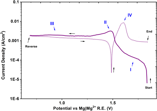
Figure 9. Cathodic polarization of Pt in molten LiCl-KCl-MgCl2 mixture containing 2.5 × 10⁻² M NiCl2 at 350 °C.
Download figure:
Standard image High-resolution imageDealloying in molten chloride salts
As mentioned, in molten fluoride and chloride salts, formation of passivating oxide films (e.g., Cr2O3) is challenging, 2,70,71 and selective dissolution (dealloying) of less-noble (LN) elements (Fe, Cr) 72–74 from Fe–Cr–Ni alloys in molten salt environments is one important challenge for structural material performance in molten salt media. Recall that dealloying is the selective electrolytic dissolution of less-noble (LN) element(s) from a homogenous metallic solid solution, 28 which results in formation of a porous structure rich in more-noble (MN) element 29 above a critical potential. 30,31 Dealloying is highly dependent on the concentration of the MN element. 75,76 In the previous work by authors, 32 it was shown that dealloying with porosity formation occur in molten Cl salts at low homologous temperature (TH = 0.36). Bulk dealloying of Cr and Fe is the dominant form of corrosion of Fe–(Cr)–Ni alloys in a eutectic molten Cl salt mixture at low homologous temperature. Selective dissolution of Fe and Fe+Cr from Fe–Ni and Fe–Cr–Ni model alloys (30–56 at% of Ni), respectively, results in porous layers rich in Ni. Still, the effects of moisture content on dealloying rate and corrosion micro-morphology, and the effect of adding a salt of the more noble alloying element on the dealloying mechanism have not been investigated.
Effect of moisture and surface oxide formation
As mentioned, moisture contamination in molten salts results in more oxidizing conditions. Reduction of H2O and H+ from HCl that is dissociated to H+ occur simultaneously. Estimating the concentration of water using electrochemical methods was performed in the In-situ electrochemical measurement of impurities section. Here results are reported from experiments carried out to reveal the effect of moisture on dealloying of the Fe70Ni30 model alloy at OCP.
Dealloying of the Fe70Ni30 model alloy was carried out in two different conditions of water content in the eutectic molten Cl salt mixture. Both salts were from the same source and purified with the same procedure, as described in the Molten salt preparation section (including the Mg ribbon step). In addition, an excess (3 wt%) amount of Mg powder was added to the second eutectic salt mixture condition to further minimize the moisture content. In the first condition, with higher moisture content (limiting current density for water reduction 1.3 mA cm−2), dealloying is more localized due to formation of local oxide layers in the presence of a large moisture content at the original alloy/molten salt interface at the initial stages of corrosion but bulk dealloying occurs up to depth of 100 μm, as seen in Fig. 10a. In comparison, the sample exposed to the second molten Cl salt mixture, with the added Mg powder (limiting current density for water reduction 0.4 mA cm−2), showed uniform dealloying throughout the surface, and penetration depth was significantly reduced, as seen in the SE micrographs of Fig. 10b. Furthermore, the presence of Mg and O containing precipitates on the dealloyed layer, and ligaments, are observed, as seen in Figs. 10c and 10d, respectively. As shown in the In-situ electrochemical measurement of impurities section, treatment of molten salts with Mg results in reducing the moisture content. Therefore, the further addition of Mg powder to the molten Cl salt mixture reduces the corrosion rate, as expected. Increasing moisture content does aid with formation of surface oxides at higher contents of the LN element, Fe. However, this effect is short-lived; the increased moisture content ultimately promotes higher corrosion rates with longer contact time in the molten Cl salt mixture with high water content.
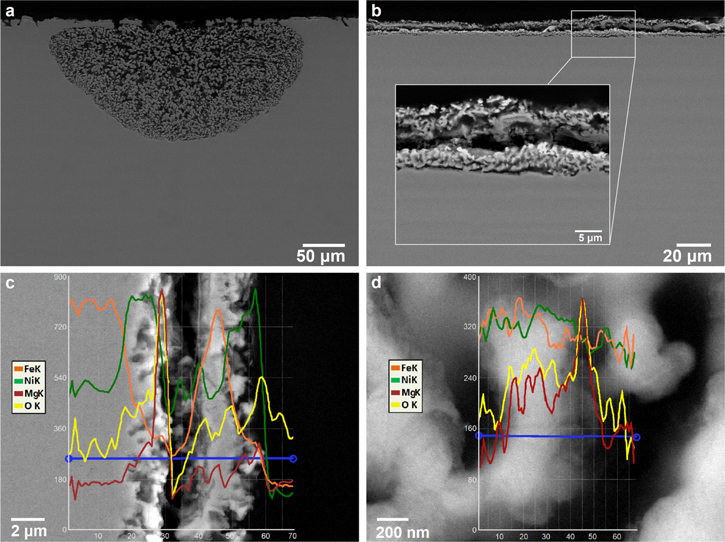
Figure 10. (a) cross-sectional SEM micrograph of the Fe70Ni30 alloy exposed to molten LiCl-KCl-MgCl2 at 350 °C for 72 h at OCP, (limiting current density for water reduction 1.3 mA cm−2). (b) cross-sectional SEM micrograph and EDX analysis at (c) the interface and (d) across a ligament of the Fe70Ni30 alloy, after exposure to molten LiCl-KCl-MgCl2 at 350 °C for 72 h at OCP (limiting current density for water reduction 0.4 mA cm−2).
Download figure:
Standard image High-resolution imageWhile dealloying is favourable at higher Fe and/or Fe+Cr contents, their higher atom fraction leads to formation of a locally protective oxide at the alloy/molten salt interface in the presence of residual moisture in molten salt.
Figure 11 shows EPMA wavelength dispersive spectroscopy (WDS) elemental maps at a selected location of the dealloyed layer formed on the Fe70Ni30 model alloy exposed to molten Cl salts at 350 °C where the limiting current density for water reduction is 3 mA cm−2. WDS maps clearly reveal the presence of an Fe oxide layer at the original alloy's surface. In addition, WDS maps reveal the core–shell structure, described in the previous study, 32 for ligaments with a Ni-rich shell surrounding a core with minor Fe content, throughout the dealloyed layer.

Figure 11. SE micrographs, BSE micrograph and corresponding WDS elemental maps (Fe, Ni, and O) for a dealloyed layer on a Fe70Ni30 alloy after exposure to molten LiCl-KCl-MgCl2 at 350 °C. Colorbar in WDS maps represent counts (arb. unit), and Lv. stands for "level"—a normalized intensity per dwell time per current that is positively correlated with concentrations within each map.
Download figure:
Standard image High-resolution imageTo further investigate surface oxide formation, model Fe–Cr–Ni alloys were prepared and exposed to a similar eutectic molten Cl salt mixture at 350 °C where the limiting current density for water reduction is 3 mA cm−2. Figures 12 and 13 show EPMA-WDS elemental maps at selected locations along the dealloyed layers formed on Fe48Cr22Ni30 and Fe30Cr22Ni48 model alloys, respectively. Results reveal a depletion of Fe and Cr and enrichment of Ni throughout the dealloyed layer, with Cr almost completely depleted in the dealloyed layer due to its lower metal/metal-ion equilibrium potential as shown in Fig. 5. Cr, O, and Mg rich precipitates are observed at the top surface, suggesting that an oxide film has formed. However, the protective ability of this oxide is very limited; dealloying still readily occurs in spite of the surface oxide, but through a pit-like mechanism.
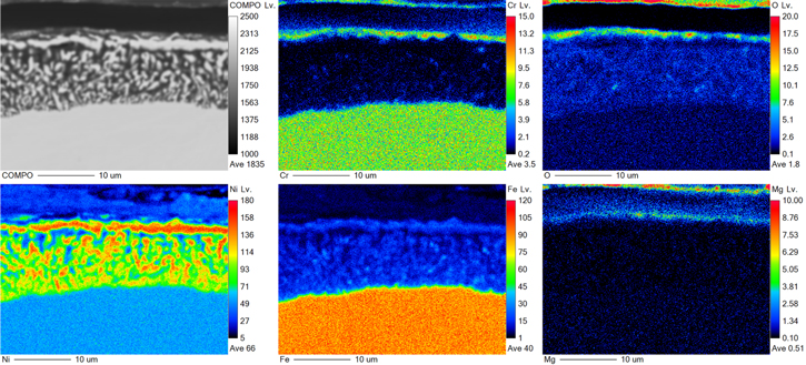
Figure 12. BSE micrograph and corresponding WDS elemental maps (Cr, Fe, Ni, O, and Mg) for a dealloyed layer on Fe48Cr22Ni30 alloy after exposure to molten LiCl-KCl-MgCl2 at 350 °C. Colorbar in WDS maps represent counts (arb. unit), and Lv. stands for "level"—a normalized intensity per dwell time per current that is positively correlated with concentrations within each map.
Download figure:
Standard image High-resolution image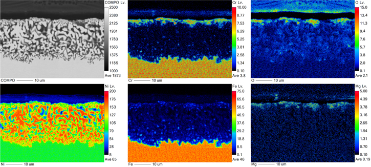
Figure 13. BSE micrograph and corresponding WDS elemental maps (Cr, Fe, Ni, O, and Mg) for a dealloyed layer on Fe30Cr22Ni48 alloy after exposure to molten LiCl-KCl-MgCl2 at 350 °C. Colorbar in WDS maps represent counts (arb. unit), and Lv. stands for "level"—a normalized intensity per dwell time per current that is positively correlated with concentrations within each map.
Download figure:
Standard image High-resolution imageResults are in agreement with other studies 77,78,79 in fluoride and chloride molten salts, which also report that a non-protective oxide layer of some alloying elements (Cr, Fe and even Mo) forms, as well as oxides of salt constituents (Mg, Be, Li). Ni enrichment is also always observed below these oxide clusters; however, prior studies 73,80–84 were performed at higher homologous temperature compared to this work. Thus, the dealloying morphology was planar, and the mechanism was controlled by solid-state mass transport.
The parting limit for dealloying
The parting limit is defined as the minimum at% of the LN element(s) required for dealloying to occur 28,30,85,86 and is associated with geometric features of the underlying crystal lattice. The phenomenon is based on percolation theory whereby a continuous availability of interconnected channels of the LN element (not necessarily of monatomic dimensions) is required for dissolution to proceed. 87 As mentioned, the parting limit is ca. 55–60 at% of LN element(s) in classical systems at ambient temperatures 28 ; even in concentrated caustic solutions at 280 °C, dealloying is greatly diminished when the Ni content exceeds 48 at% in Fe–(Cr)–Ni alloys, 32 showing that an increase in surface diffusivity can lower the parting limit, but only slightly.
The previous study by authors demonstrated that bulk dealloying with porosity formation occurs in a Fe44Ni56 model alloy, but ceases in a Fe38Ni62 alloy exposed to a LiCl-KCl-MgCl2 eutectic mixture at 350 °C at an applied current density of 5 mA cm−2. 32 Higher concentrations of Ni in the alloy inhibited dealloying. Therefore, the usual geometric parting limit for dealloying exists for Ni-based alloys in molten Cl salt mixtures, similar to aqueous solutions, but is decreased by several percent due to high surface diffusivity of Ni atoms, as revealed by the much coarser porosity in the molten salt case.
Having now developed a stable Mg∣Mg2+ reference electrode, the parting limit in the eutectic molten Cl salt mixture can be further investigated. Using model Fe–Ni alloys with similar composition as, 32 the parting limit is now examined and the conclusion strengthened using electrochemical potentiostatic measurements, which are more reliable than the galvanostatic procedure used in the previous study. 32
Dealloying is shown to occur in the Fe38Ni62 alloy in a potentiostatic experiment at 1.593 V vs Mg∣Mg2+ RE (+20 mV vs OCP), as shown by the current density vs time plot in Fig. 14; the resulting current density increases over time which is attributed to selective dissolution of Fe at this anodic potential. The SE micrograph and EDX profile shown in Fig. 15 confirm that a superficial dealloyed layer is formed when +20 mV vs OCP has been applied. This result indicates that presumably dealloying can only occur at a certain rate, and the applied 5 mA cm−2 (which gives a higher true potential) on the Fe38Ni62 in the previous study 32 was too high and led to pitting corrosion instead.

Figure 14. Current density vs time diagram for a Fe38Ni62 model alloy exposed to a molten LiCl-KCl-MgCl2 salt mixture at 350 °C at an applied potential of 1.593 V vs Mg∣Mg2+ RE (+20 mV vs OCP) for 6250 s.
Download figure:
Standard image High-resolution image
Figure 15. Surface SE (a) and BSE (b) micrographs and EDX analysis of a ligament at the surface (c) and interface (d) of the superficially dealloyed Fe38Ni62 model alloy exposed to molten LiCl-KCl-MgCl2 salts at 350 °C at an applied potential of 1.593 V vs Mg∣Mg2+ RE (+20 mV vs OCP) for 6250 s.
Download figure:
Standard image High-resolution imageHowever, unlike alloys with 30–56 at% Ni, dealloying of Fe38Ni62 results in smaller pore size, and as dealloying progresses the ligaments coalesce, and to some extent, the dealloyed layer collapses. BSE imaging shows faceting throughout the dealloyed layer, seen in Fig. 15b. Additionally, the core–shell structure in Fig. 15c shows a minor amount of Fe content at the ligament core, similar to dealloyed layers in alloys with 30–56 at% of Ni. 32 These results do not completely contradict the notion that the parting limit is higher than 38 at% Fe, because there is a clear qualitative change in the dealloying behavior between 44 and 38 at% Fe. In effect, there is a delayed formation of a healing layer of MN element, compared with ambient temperatures.
In a previous study 32 it was shown that a Fe32Ni68 model alloy underwent grain boundary attack with shallow pitting corrosion, but dealloying did not occur. To confirm this parting limit for dealloying electrochemically, a potential of 1.614 V vs Mg∣Mg2+ RE (+20 mV vs OCP) was applied to the Fe32Ni68 alloy in the eutectic molten Cl salt mixture of interest. As shown in Fig. 16, the resulting current density decays after a certain time which corresponds to dissolution of both Fe and Ni, unlike the current density vs time behaviour of Fe38Ni62 at similar applied potential (see Fig. 14). Only surface roughening and grain boundary corrosion occurs, as seen from the SE micrograph in Fig. 17. Thus, these results confirm the conclusion from prior work 32 ; the parting limit for Fe–Ni alloys is near 62 at. % Ni in the molten LiCl-KCl-MgCl2 salt mixture at low homologous temperature (TH = 0.36). Furthermore, this study reveals that dealloying in molten salts is in-line with percolation dissolution theory 33,34 ; similarly to aqueous systems, the operative mass transport mechanism for molten salt dealloying is mediated by the surface diffusion of the MN element, elemental Ni, at the alloy/molten salt interface, giving rise to fairly sharp composition thresholds.
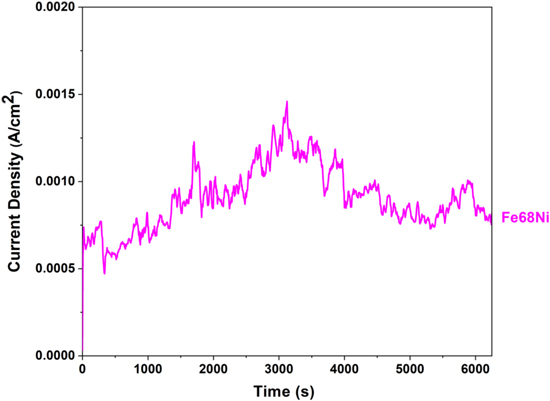
Figure 16. Current density vs time diagram of Fe32Ni68 model alloy exposed to molten LiCl-KCl-MgCl2 salts at 350 °C at an applied potential of 1.614 V vs Mg∣Mg2+ RE (+20 mV vs OCP) for 6250 s.
Download figure:
Standard image High-resolution image
Figure 17. Surface SEM micrographs of Fe32Ni68 model alloy exposed to molten LiCl-KCl-MgCl2 salts at 350 °C at 1.614 V vs Mg∣Mg2+ RE (+20 mV vs OCP) for 6250 s.
Download figure:
Standard image High-resolution imageThe effect of addition of a salt of the more noble alloying element on the parting limit
It is known that a lower threshold parting limit is possible in brass when Cu ions are added to the solution, which are nearly in equilibrium with the elemental Cu in the brass. The noble metal can be exchanged between the electrolyte and the surface whenever it is at or near its equilibrium potential with its aquo-ions. 34 The exchange current density on the surface enhances the mobility of Cu, decreasing the dealloying parting limit for these systems from ∼55 at% to 20 at% of LN element, the fcc site percolation threshold, for Cu–Zn alloys. Newman et al. 39 studied this in solutions containing the Cu I chloro complex, a dissolution product of Cu in chloride solutions. During natural corrosion in a chloride solution not initially containing any dissolved Cu I, copper ions enrich under the corrosion product, and conditions become very close to equilibrium for the Cu. The exchange current increases the mobility of the MN element, Cu. This nanoscale exchange exposes LN element atoms that can dissolve. 38
In this section, the effect of a deliberate addition of a salt of the MN element, NiCl2, to the molten LiCl-KCl-MgCl2 mixture on dealloying and the parting limit is investigated. The addition of Ni ions may shift the parting limit due to equilibration of Ni atoms on the surface with its ions in bulk solution, similar to the case of brass (discussed above) where cuprous ion addition to chloride solution results in lowering the parting limit. 34
To test whether a similar effect would occur with Ni ions in molten Cl salts, 1 wt% NiCl2 was added to the salt mixture, below its solubility limit. A cyclic polarization scan of the Fe32Ni68 alloy in the molten salt mixture without NiCl2, shown in Fig. 18a, has been carried out using the Mg∣Mg2+ RE. A similar scan on the Fe32Ni68 alloy in the mixture containing NiCl2, shown in Fig. 18b, has been carried out using the developed Ni∣Ni2+ RE (see the Reference electrode development section). As seen in these cyclic polarization scans, at OCP the corrosion rate of the Fe32Ni68 model alloy rapidly increased with the addition of 1 wt% NiCl2, as cathodic reactant, to the molten salt mixture; both anodic current density and in particular cathodic current density have increased. A potentiostatic dealloying experiment of Fe32Ni68 alloy in LiCl-KCl-MgCl2 salt mixture containing 1 wt% NiCl2 was carried at 17 mV vs Ni∣Ni2+ RE (+20 mV vs OCP); as seen in the current density vs time diagram, shown in Fig. 19, there are not any current decays, which indicates that no ohmic or diffusional control of Fe dissolution is introduced by the growth of the de-alloyed layers.

Figure 18. Cyclic polarization of the Fe32Ni68 model alloy in molten LiCl-KCl-MgCl2 salts at 350 °C, without NiCl2 using the Mg∣Mg2+ RE (a), and in molten chloride salt containing 1 wt% NiCl2 using the Ni∣Ni2+ RE (b).
Download figure:
Standard image High-resolution image
Figure 19. Current density vs time diagram of the Fe32Ni68 alloy in molten LiCl-KCl-MgCl2 salts at 350 °C; a potentiostatic hold was applied at 17 mV vs Ni∣Ni2+ RE (+20 mV vs OCP) for the mixture containing containing 1 wt% NiCl2, a potentiostatic hold was applied at 19 mV vs Ni∣Ni2+ RE (+20 mV vs OCP) for the mixture containing containing 3 wt% NiCl2.
Download figure:
Standard image High-resolution imageAs can be seen from the SE micrograph and EDX profile in Fig. 20, for the molten salt mixture containing 1 wt% NiCl2, dealloying of Fe from Fe32Ni68 results in an interconnected porous structure rich in Ni. Dealloying is far more apparent than when no Ni ions were added to solution, as was shown in Fig. 17. The initiation of dealloying in the solution with Ni ions added is localized; dealloying starts at the grain boundary and proceeds to the bulk. Fast surface diffusion of Ni atoms occurs in molten chloride salts 32,88,84 and a secondary coarsening process is in effect that grows the ligament size as seen in Fig. 20d. The average ligament size is about 5 μm which is considerably coarser compared with the ligaments formed in dealloying of Fe–Ni model alloys containing 30–56 at% of Ni in a previous study (noting that the conditions were different as dealloying was carried out galvanostatically). 32 Faceting also occurs on ligaments formed on the dealloyed Fe32Ni68, similar to the behaviour observed for Fe38Ni62 (without dissolved Ni), discussed in the parting limit for dealloying section. Faceting is an indication of fast diffusion that creates a more equilibrium type of ligament structure. Reviewing the EDX of the surface in Figs. 20e and 20f for the ligaments, it is clear that nearly all of the Fe has been dissolved from the alloy.
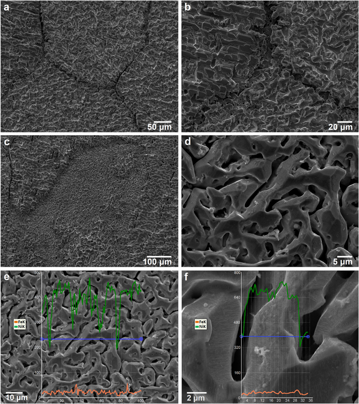
Figure 20. Surface SEM micrographs (a)–(d), and EDX analysis of the surface (e) and across a ligament (f) for the Fe32Ni68 alloy after exposure in molten LiCl-KCl-MgCl2 salts containing 1 wt% NiCl2 at 350 °C, a potentiostatic hold was applied at 17 mV vs Ni∣Ni2+ RE (+20 mV vs OCP) for 1 h.
Download figure:
Standard image High-resolution imageFigure 21 provides further cross-sectional SE imaging and EDX analysis of the Fe32Ni68 alloy exposed to the salt mixture with 1 wt% NiCl2. The dealloyed layer thickness is approximately 30 μm; this is completely different from the relatively superficial dealloying without Ni ion addition. Figure 21b reveals that the amount of Fe sharply decreases at the original alloy/molten salt interface. However, the content of Fe present in ligament cores tends to increase with depth in the dealloyed layer, as expected. Figures 21c and 21d show that the content of Fe in a ligament core near the original alloy/molten salt interface is approximately 2 at%, but for a ligament formed at the dealloyed layer/bulk alloy interface the Fe content is 16 at% for the core. Thus, the classical core–shell ligament structure is retained, but Fe can be continuously removed with increasing time of exposure to the molten salt mixture, similar to the case for the alloys with 30–56 at% Ni (without the addition of Ni ions in the molten salt). 32
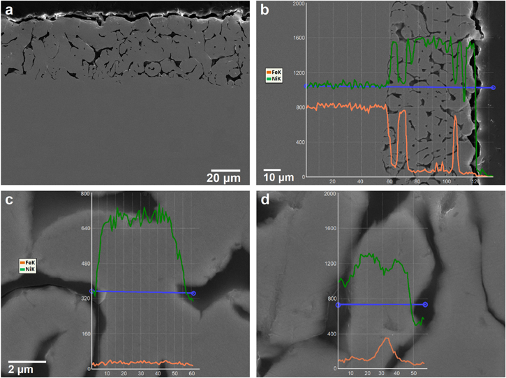
Figure 21. Cross-sectional SEM micrograph (a), and EDX analysis of the interface (b), a ligament near the original alloy interface (c), and a ligament near the dealloying front (d) for the Fe32Ni68 alloy after exposure in molten LiCl-KCl-MgCl2 salts containing 1 wt% NiCl2 at 350 °C, a potentiostatic hold was applied at 17 mV vs Ni∣Ni2+ RE (+20 mV vs OCP) for 1 h.
Download figure:
Standard image High-resolution imageComparing Figs. 17 and 20 shows a significant effect of Ni ion addition to the original molten salt eutectic mixture. Equilibrating the Ni atoms at the alloy surface with the dissolved Ni2+ ions in the molten salt strongly enhances the surface mobility of the Ni atoms, especially after the dealloying front has passed by. Under these conditions, there will be an exchange current on the surface of the alloy, leaving atomic sites on the surface open temporarily to allow the electrolyte access to the underlying LN atoms (Fe) which are subsequently dissolved. This behaviour allows for maintaining electrolytic dissolution of Fe for the model alloy with higher Ni content. Thus, the parting limit is further shifted to higher Ni contents if Ni ions are present in the molten salt. Therefore, the previously reported parting limit for molten Cl salt at low homologous temperature (44 at% of Fe) in the case of Fe44Ni56 32 is decreased to a value below 32 at% Fe, when 1 wt% NiCl2 is present in the eutectic molten salt at a small applied anodic overpotential at the same temperature (and same initial impurity content). The dealloying behaviour for the Fe32Ni68 alloy shown here in molten Cl salts containing NiCl2 is similar to the dealloying of Zn from brass in which the dealloying parting limit is close to the fcc site percolation threshold (20 at%) 34 due to the presence of cuprous complex ions in solution.
Further dealloying experiments on the Fe32Ni68 model alloy were carried out with 3 wt% NiCl2 added initially to the eutectic molten Cl salt mixture to study the effect of increasing the concentration of ions for more noble element. The current density vs time diagram for the Fe32Ni68 model alloy exposed to mixture containing 3 wt% NiCl2 in a potentiostatic experiment at 19 mV vs Ni∣Ni2+ RE (+20 mV vs OCP), shown in Fig. 19, indicates that rapid de-alloying occurred in the mixture containing a higher amount of Ni ions.
As can be seen from the SE micrographs in Fig. 22a, dealloying occurs at grain boundaries and to some extent across the surface of the alloy. When compared with the case of 1 wt% NiCl2, in Fig. 20, the sample exposed to the salt mixture with 3 wt% NiCl2 also underwent corrosion, but the dealloying is more obvious at the surface, and the ligament size is slightly finer. Figures 20e and 20d and Figs. 22c and 22d show that the Fe content in ligament cores is slightly lower in the salt mixture containing 3 wt% NiCl2 compared with the sample exposed with 1 wt% NiCl2.

Figure 22. Surface SEM micrographs (a), (b), and EDX analysis of the surface and across a ligament (c), (d) for the Fe32Ni68 alloy after exposure in molten LiCl-KCl-MgCl2 salts containing 3 wt% NiCl2 at 350 °C, a potentiostatic hold was applied at 19 mV vs Ni∣Ni2+ RE (+20 mV vs OCP) for 2 h.
Download figure:
Standard image High-resolution imageCross-sectional SE micrographs, seen in Fig. 23, on the dealloyed Fe32Ni68 alloy after exposure to the molten Cl salt mixture with 3 wt% NiCl2 reveal an interconnected porous structure. Compared with the sample exposed to 1 wt% NiCl2 (seen in Fig. 21), the pore size in the sample exposed to the salt mixture with 3 wt% NiCl2 is increased; dealloying first occurs at the grain boundaries and progresses significantly through the bulk alloy. EDX analyses in Figs. 23d and 23e show that Ni enrichment persists throughout the dealloyed layer, and the ligament profile reveals the core–shell structure as seen in Fig. 23f, with a Ni-rich shell surrounding a core with a residual amount of Fe, between 2–4 at%, which is less than the amount of Fe detected in ligament cores of the dealloyed layer formed in molten Cl salts containing 1 wt% NiCl2 (see Fig. 21). This indicates that a higher concentration of Ni ions increases the surface diffusivity of elemental Ni atoms or at least the exchange rate of Ni at the surface. Cross-sectional SE micrographs, seen in Figs. 23a and 23c, shows gross grain boundary opening and dissolution and section loss at higher concentrations of NiCl2. These results indicate that the concentration of NiCl2 is influential in promoting rapid dealloying; as dealloying progresses with time, nearly all of the Fe is dissolved from the ligaments. As seen in Fig. 23c, the fraction of the load-bearing ligaments in the porous structure is lowered near the original alloy/molten salt interface and there are not enough strong and stiff inter-connected porous structure; as rapid coarsening hinders smallness of porous structure with time and therefore significantly reduces network connectivity, thus there appear lesser number of ligaments per volume throughout the dealloyed layer. Thus, secondary dealloying and rapid coarsening result in breaking-up of ligaments.

Figure 23. Cross-sectional SEM micrographs (a)–(c), and EDX analysis across the dealloyed layer (d), (e) and across an individual ligament (f) for the Fe32Ni68 alloy after exposure in molten LiCl-KCl-MgCl2 salts containing 3 wt% NiCl2 at 350 °C, a potentiostatic hold was applied at 19 mV vs Ni∣Ni2+ RE (+20 mV vs OCP) for 2 h.
Download figure:
Standard image High-resolution image
These observations are consistent with the dealloying mechanism in which selective dissolution of the LN element, Fe, is sustained by the surface diffusion of the MN element, Ni, at the solid electrolyte interface. The fact that Ni is almost at equilibrium with its ions in the local environment of the electrolyte increases the surface mobility of Ni atoms; this exchange reveals Fe sites that can dissolve, and the dealloying threshold is being lowered. It is shown that addition of an increasing amount of NiCl2 increases the corrosion rate of Fe32Ni68 (and Fe–Ni alloys in general) by promoting exchange of Ni at the surface and easier dissolution of Fe. Importantly, at a low homologous temperature (350 °C, TH = 0.36) the parting limit for selective dissolution of Fe drops to a value less than 32 at%, depending on Ni ion concentration. Thus, we postulate that the dealloying parting limit has two correlations in molten Cl salts, one with temperature and another with the amount of Ni ions in the molten salts. The moisture content is also important, and formation of a surface oxide may slow dealloying (temporarily) or result in pit-like features; however, moisture does not fundamentally change the parting limit at the contaminant level of interest.
This study confirms that dealloying at lower temperatures, 350 °C, broadly obeys the same rules as aqueous dealloying, but with a lower parting limit. There are cases where dissolution of reactive elements from Ni-alloys in molten salts occurs at very high temperatures, below the threshold parting limit that was observed at 350 °C. Selective dissolution of reactive elements from Hastelloy N, Alloy 625, Haynes 230, Alloy 800, and 316 stainless steel in molten halide salts have been reported in the literature 73,80–84,88 and occurred over a wide range of LN elements. The dealloying mechanism changes at very high temperature, and the operative mass transport mechanism becomes more related to bulk lattice diffusion and thus the dealloying parting limit could drop to very low values. Another study by authors presents the dealloying mechanisms in similar eutectic molten Cl salt mixtures at higher temperatures. 89
Conclusions
An electrochemical corrosion study has been carried out in a eutectic molten chloride salt mixture at 350 °C. While this is historically a challenging topic, a magnesium reference electrode was developed and calibrated in this work to examine, electrochemically, the impurity content, the effect of moisture on dealloying, the parting limit of Ni–Fe alloys in molten Cl salts, and the effect of Ni ion addition to molten Cl salt media. The following general conclusions can be drawn from this study:
- 1.Water and oxygen impurities in the eutectic molten Cl salt mixture were removed via step-wise heat treatment under Ar gas to avoid hydrolysis, followed by convecting the medium through a bundle of Mg ribbons to remove the minor H2O and HCl. The residual amount of water was measured in situ using cathodic polarization of Pt. Electrochemical measurements confirmed that the developed purification procedure, with the Mg ribbon, decreased the moisture impurity by approximately 30-fold.
- 2.A dynamic reference electrode is based on the formation of a K/Li or Mg thin layer electrodeposited on a W working electrode by reduction of their ions. The reference potential could be monitored against the redox system of salt constituents. Using the Mg-DREs as a calibration reference, a Mg rod was shown to operate close to a true Mg∣Mg2+ RE, without the need for encasing materials if MgCl2 is part of the mixture. The RE is stable and results are reproducible.
- 3.The presence of minor moisture results in formation of oxides of Cr and Fe (and Mg, Li and O containing precipitates) in alloys with high contents of Fe and/or Fe+Cr, but dealloying proceeds via a pit-like mechanism. Therefore, while minor moisture content allows for short-term passivity, over time those oxides break down and bulk dealloying proceeds at the OCP.
- 4.Superficial dealloying could be detected in a Fe38Ni62 model alloy at low homologous temperature in the eutectic molten Cl salt mixture at some electrochemical conditions (after purification).
- 5.The addition of Ni ions to the molten salt as NiCl2 results in dealloying of Fe in the Fe32Ni68 alloy at low homologous temperature (TH = 0.36). The usual parting limit for dealloying drops to a value less than 32 at% of the LN with addition of ions of the MN alloying element. The severity of dealloying in the Fe32Ni68 alloy increased with increasing NiCl2 content.
Acknowledgments
The authors acknowledge financial support for this work from the Natural Sciences and Engineering Research Council of Canada (NSERC), and the University Network of Excellence in Nuclear Engineering (UNENE). The authors are grateful to Dr Yanan Liu in Department of Earth Science at the University of Toronto for assistance with electron probe microanalyzer.