

Abstract
The rise of wearable technology has gradually shifted modern health monitoring from clinical to personal use. Smart wearables can collect physiological signals and show them directly on a smartphone. In contemporary healthcare scenarios, this big data could aid medical doctors in online health analysis. Most currently available wearables are designed to monitor specific health parameters, while the combination of many devices is practically not convenient and not cost-effective. Therefore, a strong trend is towards the development of multifunctional devices. This demands, however, alternative sources of power other than conventional batteries. The concept of human-body-powered biosensing textiles (HBBTs) addresses this challenge. By harvesting energy produced from the human body such as motion, pressure, vibration, heat, and metabolites and converting them into electricity, HBBTs could potentially work without a battery. Additionally, the textiles themselves provide a suitable substrate for interconnects and biosensors, such that a system based on HBBTs could provide multifunctional health monitoring. This review explains the fundamental theories, the classification, the energy-conversion efficiency assessment, and the possible biomonitoring applications of HBBTs. Furthermore, we discuss the challenges for technology maturity and the perspectives of HBBTs in shaping the future of health monitoring.
Export citation and abstract BibTeX RIS

This is an open access article distributed under the terms of the Creative Commons Attribution 4.0 License (CC BY, http://creativecommons.org/licenses/by/4.0/), which permits unrestricted reuse of the work in any medium, provided the original work is properly cited.
Wearable technology in healthcare has evolved from medical diagnostic devices in the clinic into personalized or remote health monitoring, health data analytics, early detection of diseases and/or disorders, as well as social lifestyle—thanks to the recent advancement of innovative accessories such as smartwatches, smart bracelets/wristbands, smart rings, etc. This evolution is not only driven by the development of the System-on-Chip (SoC) technology but also by the advancement of wearable biosensor technology itself. 1 People can now monitor their heart rate and oxygen saturation during exercising or sleeping. 2,3 Even electrocardiograms (ECG) can be monitored using a smartwatch. 4 Besides, doctors could also monitor seizures or tremors for Parkinson's disease patients remotely. 5,6 Additionally, smart wristbands and smartphone apps can assist diabetic patients in managing their intakes and physical activities in a more controlled manner by providing online scheduling and automatic reminders. 7 As a result, those smart accessories could improve the quality of our life. Furthermore, to realize a large biosensing area at different body sites and considering specific applications such as for sports science, especially for athletes' fitness monitoring, for those having risky professions (firefighters, military, construction workers), as well as for footstep or gait analysis for neurological disorders evaluation or monitoring, all these have led to the emerging study on electronic textiles (e-textiles), which is sometimes also defined as wearable 2.0. 8,9 Textiles are considered the ideal wearable media for the integration of systems. Unlike smart accessories, textiles are a basic need for human beings. Thus, there would be less hesitation for the end-users to wear textiles capable of sensing.
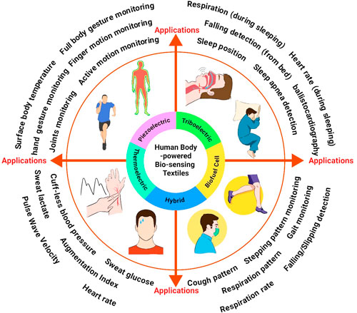
Any biosensing textiles are generally constructed from either one of these essential three textile elements, i.e., fiber, yarn, or fabric, as illustrated in Fig. 1A. Fiber is the fundamental element of e-textiles. Many fibers are interlocked (twisting, twinning, or blending) to form a yarn or a thread. From these yarns or threads, the 2D or 3D fabric-based biosensing textiles can be created by knitting, weaving, braiding, tufting, or felting—noting that most fabric-based biosensing textiles are knitted or woven. 10,11 Thus, the most basic method to realize e-textiles is by engineering a fiber or a yarn, such that it contains the sensing elements and the electrical connections. Alternatively, biosensing textiles can also be realized by engineering the fabric. Unlike fiber or yarn, fabric provides a 2D surface area for material modification. Thus, facile material deposition or fabrication processes might potentially be applied to the fabric, which is sometimes considered as a "new silicon substrate."
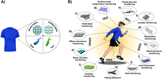
Figure 1. Illustration of (A) the basic elements that construct a textile and (B) the wide range of HBBTs' biomonitoring applications (a-l) along with the corresponding five different energy harvesting strategies from the body, i.e., PENG, TEG, BFC, TENG, and HNG. (a) Adapted with permission from Ref. 109. Copyright 2018 American Chemical Society. (b) Adapted from Ref. 245. Copyright 2019, with permission from Elsevier. (c) Adapted from Ref. 97. Copyright 2018 with permission from Elsevier. (d) Adapted with permission from Ref. 90. Copyright 2018 Royal Society of Chemistry. (e) Adapted from Ref. 67. Copyright 2019, with permission from Elsevier. (f) Adapted with permission from Ref. 246. Copyright 2021 Springer Nature. (g) Reproduced with permission from Ref. 175. Copyright 2020 Science Advances. (h) Reproduced with permission from Ref. 15. Copyright 2018 Wiley-VCH. (i) Adapted from Ref. 169. Copyright 2020 with permission from Elsevier. (j) Reproduced with permission from Ref. 111. Copyright 2020 Springer Nature. (k) Adapted from Ref. 148. Copyright 2018, with permission from Elsevier. (l) Reproduced with permission from Ref. 149. Copyright 2018 Wiley-VCH.
Download figure:
Standard image High-resolution imageMoreover, the unique characteristic of textiles such as clothes is that they could cover a large area of our body, such that more than one biosignal could potentially be measured. For example, the body motions/gestures, 12 the heart rate (HR), 13 the pulse pressure (PP) and/or the blood pressure (BP), 14,15 the electrocardiogram (ECG), 16,17 the electromyography (EMG), 18 the surface body temperature, 19 the respiration, 20 and the biochemicals. 21 Furthermore, the e-textiles can also be integrated into a sensor node for the Internet of Things (IoT) or into a body sensor network (BSN) system by combining them with signal processing circuitry and wireless modules. 22–24 However, there is still a lack of suitable power sources that are convenient to wear, easily integrable into the textile, and able to generate sufficient electrical power for the sensors and/or electrical circuits for any of the applications of e-textiles as mentioned earlier. Thus, it is necessary to develop innovative power source strategies for e-textiles.
Even though it could provide a stable and large amount of power, a conventional battery is not preferred for wearable applications since it is typically rigid and bulky. Its weight is usually the heaviest among all other components. The best way to use it is when the subject/person-of-interest is stationary. Research groups have started to explore self-powered/battery-less systems to address this challenge. The wireless energy harvesting utilizing WiFi, near field communication (NFC), or radio frequency identification (RFID) technology is a straightforward strategy to realize such a system. 25–29 However, this system requires additional power management and communication modules, which increase the system complexity to be implemented on the textile. Ambient light from the Sun and/or indoor lighting can be a promising alternative energy source. 30–32 Nonetheless, the availability of solar energy is usually not stable, and the generated power is insufficient, especially during dynamic body movements or indoor use. This is one of the reasons for the emergence of harvesting energy from our bodies. Actually, in our daily life, the body generates energy in the forms of kinetic, chemical, and thermal energy that can be harvested and converted into useable power for electronic devices. 33–35 Besides, the origin of these energy sources, e.g., body motion or body vibration, 36–39 metabolites contained in sweat, 40,41 and surface body temperature, 42 could also be interpreted as a health indicator. There are various kinds of materials, which can simultaneously sense those stimuli and convert them into electricity. In general, those materials are named energy harvesting materials. They could be sub-categorized based on the stimulus to which they respond, i.e., the piezoelectric nanogenerator (PENG), the triboelectric nanogenerator (TENG), thermoelectric generator (TEG), the biofuel cell (BFC), and the hybrid nanogenerator (HNG). As stated above, textiles provide conformance and coverage of large body areas. Hence, textiles could perfectly be utilized as a "substrate" for wearable devices, including energy harvesting materials and biosensor devices. This further motivates the development of a new class of wearables, i.e., the human-body powered biosensing textiles (HBBTs), as illustrated in Fig. 1B.
The generated output power of HBBTs is typically at μW levels. 43–45 Thanks to the progressive improvement of integrated circuit design, some signal processing circuits and ultra-low-power microcontrollers consume only a microwatt of power nowadays. 46–48 Thus, the generated power from the HBBTs could suffice to power up complex circuits and self-powered autonomous alert systems. Furthermore, being as fibers/yarns or fabrics, HBBTs could also be implemented in large dimensions enabling a large area sensing and mapping our body's health. 49–51 Further details about the elemental classification of HBBTs, how each type of HBBTs works and harvests the energy from the human body, and the practical applications of the HBBTs to monitor our body's health are discussed in the following sections. Moreover, the challenges and future perspectives of the HBBTs are also discussed.
Elemental Classification of HBBTs
Fiber- or yarn-based HBBTs
As previously explained, the biosensing capability of textile is realized by engineering the fiber or yarn. It contains the sensing elements and the metal contact or the electrical connection. The straightforward method synthesizes a fiber or a yarn with specific biosensing properties. Fiber/yarn-based HBBTs can be made from a variety of materials. For example, the elastic thermoplastic polyurethane (TPU) or polyvinylidene fluoride (PVDF) nanofiber membrane could be modified by coating it with carbon nanotubes (CNTs), 52 graphene, 53 CNT/silver nanoparticles (CNT/AgNPs), 54 or poly(3,4-ethylenedioxythiophene) (PEDOT). 55 Carbon-based nanomaterials are the most explored materials, i.e., carbon nanotube (CNT) and graphene. The typical as-prepared graphene fiber shows a porous structure, which provides sites for incorporating other materials to produce a composite graphene fiber. 56 Graphene fibers have an excellent electrical conductivity (∼104 S m−1) but have a relatively low mechanical strength (∼102 MPa). 57,58 Meanwhile, the CNT fibers have higher electrical conductivity (∼104 − 104 S m−1) and much higher mechanical/tensile strength (3 GPa). 59 The tensile strength could be increased to 80 GPa by improving the parallel alignment of the CNTs. 60 However, it is noticeable that CNTs might be harmful since there is a possibility that the CNTs penetrate living cells, especially the short-length CNTs. 61
Owning an as-is fiber/yarn structure and an excellent mechanical and electrical characteristic, many HBBTs are based on CNTs fiber/yarn, especially the TEG and BFC-based HBBTs. In the case of the TEG-based HBBT (TEG-HBBT), the CNT yarn itself can even be used as the contact electrode, eliminating the need for additional metal deposition. 62 Moreover, the yarn structure of the CNTs makes it easy to be integrated into a textile as it can be directly stitched or sewn into fabrics so that a wristband and a watch strap TEG-HBBT could be realized. 63,64 Aside from the excellent mechanical and electrical characteristics, the CNTs can also be easily functionalized via organic functionalization with various organic molecules. In particular, CNTs have shown excellent electrocatalytic performance with redox enzymes because of their narrow diameter size that can approach the active site of the enzymes. 65 Hence, CNT has become the mainly used electrode material to realize BFC-based HBBT (BFC-HBBT). Using a composite of PEDOT/MWCNT nanomembrane yarns, C.H. Kwon and co-workers developed high-power BFC textiles with a maximum power density of 2.18 mW cm−2 at given 60 mmol l−1 glucose. 66 Furthermore, S. Yin and co-workers demonstrated a sewn glucose-fueled textile cloth BFC based on carbon fibers, which generated an output voltage of 1.9 V and was capable to power up an LED. 67
For fiber-based TENG-HBBT, plenty of materials have been developed, which mostly are the core-sheath/coaxial structure of metal coated rubbers/polymers. 68–71 Moreover, since almost any fiber material could be used to construct a TENG-HBBT, various unique applications could be realized using a fiber-based TENG-HBBT. L. Ma and co-workers proposed a flame-retardant TENG-HBBT carpet, made of conductive Ag yarns core and cotton-polyimide yarns sheath, that could trigger an emergency location alert by just tapping on the carpet and a real-time route guidance by light illumination upon foot stepping for evacuation in the case of fire. 72 Besides, by encapsulating an elastomeric composite consisting of silicone rubber and a self-luminescent SrAl2O4:Eu2+ nanoparticles on a stainless-steel thread, L. Li et al. were able to realize an autoluminescent fiber-based TENG-HBBT. 73 The fabricated fiber-based TENG-HBBT had a uniquely inherited property that it could self-emit a visible green light after absorbing visible light for several minutes and simultaneously generate electricity upon taping. This development could lead to a new trend in e-textiles technology, i.e., the self-glowing and power generating e-textiles. Aside from coating technique, recently 3D printing technique has also been used to fabricate a core-sheath fiber-based TENG-HBBT. 74,75
Additionally, the electrospinning technique is also one of the most popular techniques for producing nanofiber materials. The nanofibers produced by this technique are also called nonwoven fabrics. 76,77 Moreover, not only in the fiber-based TENG-HBBT, but in fiber-based PENG-HBBT several groups have also recently developed core-sheath fiber structure to produce microfibers of PENG-HBBT, so that it eases the integration of the microfibers into textiles by using conventional sewing methods, such as weaving, knitting, or stitching. 78,79 Generally, for PENG-HBBT, the core-sheath microfibers are commonly built on a conductive yarn/thread as the core as well as the inner electrode, an electrospun PVDF nanofibers as the sheath as well as the piezoelectric material, and another thin-film metal or conductive yarn/fiber as the outer electrode. The piezoelectric PVDF nanofibers can be directly electrospun or manually twinned on the surface of the conductive yarn/thread, while the outer electrode layer or fibers could be deposited by vacuum evaporation or sewing methods, respectively. 80–82
Fabric-based HBBTs
As previously explained, from multiple yarns or threads, 2D or 3D fabric can be formed by knitting, weaving, braiding, tufting, or felting process. In general, for fabric-based HBBTs, the fabrics are typically used as the sensing element themselves (using surface modification or materials engineering) or only as a substrate. Commonly, the fabrics are made of natural materials, such as cotton, 83 silk, 84 wool, 85 and linen, 86 rather than synthetic ones. Cotton and silk fabrics are the widely used textile material to realize the fabric-based HBBTs. However, when the stretchable application is considered, the elastic fabrics based on nylon/spandex or polyester/spandex are used instead of the natural fabrics. 87 Furthermore, as fabric provides a much larger substrate area, facile fabrication processes and more complex system integration could be realized.
Using a facile screen-printing method, various types of HBBTs could be made. As demonstrated by Joseph Wang's group, a stretchable and large area BFC-HBBT on elastic nylon-spandex textile could be realized via screen-printing technique. With optimizing the materials and implementing a serpentine pattern, the BFC-HBBT could even endure a 100% cyclic strain without showing any performance degradation. 88,89 With the screen-printing technique, the ink materials can also be printed in a particular printing pattern on the fabrics. M. Jung et al. reported a screen-printed 5 × 5 array of TEG-HBBT, which could map the temperature distribution upon contact with an object having a temperature difference. 90
Furthermore, as fabric is basically made of interlaced fibers or yarns, different types of HBBTs could be realized by weaving two different functional fibers or yarns materials. The fabric-based TENG-HBBT is one type of HBBT, which is commonly realized by that kind of weaving method. 91–95 J. Chen and co-workers demonstrated a fabric-based TENG-HBBT integrated with a supercapacitor, which all were made by a traditional shuttle-flying weaving craft method. 96 The woven TENG-HBBT worked in a freestanding TENG (f-TENG) mode. Thus, by harvesting the energy from the arm movement during running, the sewn (under the arm of a sweater) f-TENG, connected with four-series of sewn supercapacitors, was able to sustainably power an electronic watch. Moreover, in the effort of increasing the output power density, the fabric-based TENG-HBBT can also be made into a 3D weaving structure as reported by K. Dong et al. 95 Here, they stacked the polydimethylsiloxane (PDMS)-coated 3-ply-twisted stainless steel/polyester fiber yarns on top of each others with the stainless steel/polyester fiber yarns were placed in between to serve as the electrode. As the warp-weaver or the Z-direction binder, they used nonconductive cotton yarns. As the result, the output power density could be increased a lot, reaching the peak of 263.36 mW m−2 -at 132 MΩ of load resistance.
For fabric-based PENG-HBBT, most of the devices are constructed in a sandwich/stacking structure, which a piezoelectric materials is sandwiched in between two conductive fabric electrodes. 97–101 Similar with the fiber-based PENG-HBBT, the piezoelectric materials of the fabric-based PENG-HBBT are also commonly made by electrospinning technique. Thus, in general the basic structure of the piezoelectric materials of the PENG-HBBT is nanofibers. More specifically, the electrospun PVDF, its copolymers, and its composites are the widely used piezoelectric materials in PENG-HBBT. 102,103 B. Mahanty and co-workers utilized this technique to realize a PENG-HBBT based on PVDF/MWCNT electrospun nanofibers. 104 The device could reach a peak power density of 79.5 mW m−3 and was able to harvest biomechanical energies from the wrist bending and arm movement. Aside of PVDF, zinc oxide (ZnO) nanorod arrays have commonly developed to realize PENG-HBBT. A facile material preparation via sol-gel hydrothermal method has been generally used to prepare the ZnO nanorod arrays. 102 In hydrothermal process, the sample is firstly dipped/submerged in a precursor solution and sequentially annealed. Thus, by adjusting the solution volume and sample size, it is possible to realize a large film area of PENG-HBBT using this hydrothermal-based ZnO nanorod arrays as previously proposed by Z. Zhang et al. 98 In their work, the PENG-HBBT was realized by sandwiching ZnO nanorod arrays in between two sheets of silver (Ag)-coated nylon fabrics. The ZnO nanorod arrays were grown on the surface of Ag-coated nylon fabric via hydrothermal method. By making a larger size of PENG-HBBT (5 × 5 cm2), it could power up several LEDs by foot stepping. In overall, this elemental classification of HBBTs along with the commonly used materials, the fabrication methods, as well as the advantageous and the disadvantageous of each approach are summarized in Table I.
Table I. Elemental classifications of HBBTs and the advantageous and disadvantageous of each approach along with the fabrication and the integration methods.
| Elemental classification | HBBT type | Common materials | Fabrication methods of HBBT | Integration to textiles | Advantageous | Disadvantageous |
|---|---|---|---|---|---|---|
| Fiber-based | PENG | PVDF, PVDF block copolymers, PVDF composite, ZnO nanowires | electrospinning and twinning/braiding, melt spinning, thermal drawing, coating | Knitting, stitching weaving | More freedom to tune the material properties | Relatively complicated fabrication process |
| Allow a complex or arbitrary knitting pattern design and improve the aesthetics | Twisting process may cause abrasion between fibers | |||||
| Seamless integration with any kind of textile materials | Weak interfacial bonding between functional materials and the textile fibers, lead to cracking/delamination | |||||
| TENG | polymer materials or polymeric/textile yarns/threads, conductive yarns/threads | Coating, twisting/twinning, 3D printing | ||||
| TEG | carbon materials (CNT yarn/thread), PEDOT:PSS, PEI, inorganic bismuth telluride-based alloys | thermal drawing, aerogel spinning, coating, electrospinning | Limited number of active areas | |||
| BFC | Electrode: Carbon-based yarn/thread/fiber | |||||
| Enzyme: Glucose oxidase, bilirubin oxidase, lactate oxidase | Coating, enzyme immobilization | |||||
| Fabric-based | PENG | PVDF, PVDF block copolymers, PVDF composite, nanostructured ZnO, BaTiO3 nanowires | hydrothermal, electrospinning, 2D/3D weaving | sandwiching/stacking, knitting, stitching | Direct integration with the textile is possible | Short circuit problem if the film is damaged |
| Easy for large-area fabrication | ||||||
| higher output power is expected | For TENG-HBBT, surface engineering is necessary to improve the device output performance | |||||
| Inherited some extrinsic stretchability from the weaving pattern of the fabric | ||||||
| TENG | Polymer materials, metals, textile materials | 2D/3D weaving, stacking | Knitting, stitching | |||
| TEG | Carbon materials (CNT, graphene), PEDOT:PSS, inorganic bismuth telluride-based alloys | screen-printing, coating, drop casting, enzyme immobilization | direct integration | |||
| BFC | Electrode: Carbon materials, Ag/AgCl | |||||
| Enzyme: Glucose oxidase, bilirubin oxidase, lactate oxidase | screen-printing | direct integration |
HBBTs Classification Based on the Power Generation Mechanisms
Piezoelectric nanogenerator-based HBBT (PENG-HBBT)
Mechanical energy is utilized as the most common source of energy in wearables. It is readily available by the movement of body parts. It offers an ample amount of power compared to other energy sources such as thermal or biofuel in principle. PENG is one type of nanogenerator, which converts mechanical energy into electricity. Therefore, high output power can be expected from PENG-HBBT. The basic principle of piezoelectricity or electricity generation of PENG is that when PENGs experience a strain, shear, and/or stress, a piezoelectric potential will be produced, as depicted in Fig. 2a. In detail, the piezoelectric material is typically sandwiched in between electrodes. After the polarization process, opposite charges will appear within the piezoelectric materials (Fig. 2ai). When an external force is applied, the volume of the piezoelectric material will deform, and a negative strain is produced. Accordingly, the charge centers will re-align, and electric dipoles will be formed. As a result, a piezoelectric potential is generated between the electrodes. Current flow can be observed if an external load is connected to the electrodes (Fig. 2aii). When the external force is further increased until the piezoelectric material reaches its maximum pressed state, the piezoelectric material experiences the highest polarization density, which results in no current flow between the electrodes (Fig. 2aiii). Upon releasing the external force, the electrons flow back and return to the initial state (Fig. 2aiv). At this state, a reversed current can be observed.
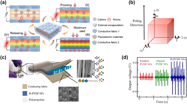
Figure 2. (a) Basic energy harvesting principle of the PENG-HBBT. Reproduced with permission from Ref. 49. Copyright 2020 Wiley-VCH. (b) Direction index for a poled piezoelectric material in rectangular crystallographic system. Adapted with permission from Ref. 108. Copyright 2020 Royal Society of Chemistry. (c) All-fiber-based wearable PENG-HBBT, composed of Pt-PVDF NFs (piezoelectric) and conducting fabrics (electrodes). (d) Energy harvesting performance comparison of the PENG-HBBT using Pt-PVDF NFs and using PVDF NFs. Adapted from Ref. 97. Copyright 2018 with permission from Elsevier.
Download figure:
Standard image High-resolution imageIt should be noted that the piezoelectric potential is typically an AC signal with a varying frequency. Therefore, a rectifier circuit is usually required to produce a DC signal output. Moreover, there are plenty of available piezoelectric materials to produce piezoelectricity, generally classified as a piezoelectric crystal, piezoelectric ceramics, piezoelectric polymers, and piezoelectric composites. 105 Only the piezoelectric crystal is not commonly used for textile applications.
Generally, the piezoelectric effect of any piezoelectric materials can be expressed by the piezoelectric coupling (Eqs. 1–2): 106


where S is the strain, sE is the elastic compliance in a constant electric field, T is the stress, d is the direct or converse piezoelectric effect, E is the electric field, D is the electric displacement, and εT is the dielectric permittivity at constant stress. Meanwhile, the electrical energy output of the PENGs is affected by at least three factors: the magnitude of the applied external mechanical energy, the energy conversion efficiency of the piezoelectric materials, and the stored electrical energy. 107 The figure of merit (FOM) is then defined to assess the energy conversion efficiency of the piezoelectric materials. Due to different variations of piezoelectricity generation modes, the FOM of a PENG is grouped into five constants, as shown in Table II. 108
Table II. Figure of merit (FOM) of the piezoelectric materials.
| Piezoelectric constant | Description |
|---|---|
| Piezoelectric strain (d) | The strain magnitude of a piezoelectric material, which is induced by an external electric field |
| Piezoelectric voltage (g) | A constant, which is related to the induced electric field and the applied external stress |
| Electromechanical coupling factor (k) | Piezoelectric activity during deforming/vibrating |
| Mechanical quality factor (Qm) | Quantify the amount of mechanical losses |
| Acoustic Impedance (z) | A measure of a resistance for an ultrasound when it travels penetrating through a piezoelectric material |
In general, to realize a biosensing textile based on a piezoelectric nanogenerator (BT-PENG), the most common device structure is the sandwich structure. The piezoelectric material is placed between two conducting fabrics that serve as the electrodes. 97,98,109–111 For this sandwich structure and when the piezoelectric material is deposited along with the weft or warp yarns, the output voltage in mode d31 could be expressed as in Eq. 3:

where V31 is the output voltage in mode d31, σxx is the applied stress, g31 is the voltage coefficient, and t is the thickness of the piezoelectric material. The subscript indexes are a reduced-order tensor notation, which indicates the direction of the electrical and mechanical parameters. In general, the direction indexes of piezoelectric material are illustrated in a rectangular crystallographic system, as depicted in Fig. 2b. The notation 4, 5, and 6 represent the shear constants.
To improve the FOM of the piezoelectric material of a PENG-HBBT, S.K. Ghosh et al. incorporated the noble metal, platinum nanoparticles (Pt-NPs), into 1D poly(vinylidene fluoride) nanofibers (PVDF NFs) arrays. 97 Copper-nickel polyester conductive fabrics were used as the top and bottom electrodes, as shown in Fig. 2c. The Pt-PVDF NFs dramatically improved its electric field-induced strain amplitude, which increased by 200%. Consequently, the electrostriction coefficient also increased, which improved the piezoelectric strain constant (d33) by 100%. This led to the much-improved electrical output of the Pt-PVDF NFs compared to the neat PVDF NFs, as shown in Fig. 2d. Furthermore, the Pt-PVDF NFs also had a lower dielectric constant than the neat PVDF NFs. Since the piezoelectric voltage constant is inversely proportional to the dielectric constant, the Pt-PVDF NFs exhibited a higher piezoelectric voltage constant (g3j). As a result, by repeated hand-punching, the Pt-PVDF NFs demonstrated a high output power density of 22 μW cm−2 with a corresponding open-circuit voltage (VOC) of ∼30 V and short-circuit current (ISC) of ∼6 mA at the load resistance of 1 MΩ. The Pt-PVDF NFs were able to instantly power up 100 lEDs and a digital calculator via a 1 μF capacitor. Using a similar concept, K. Maity and co-workers proposed sugar-incorporated electrospun PVDF nanofiber webs to realize a high power density piezoorganic nanogenerator-based biosensing textile (PONG-HBBT). 109 In detail, sugar suppressed the nucleation of the α-phase but favored the formation of the β-phase. Meanwhile, the PVDF matrix served as an encapsulation for the sugar from ambient moisture and oxygen. Thus, this synergistic effect led to a significant improvement of the PONG dielectric constant by almost 100%, enhancement of the FOM by 46%, and robust stability under the variation of ambient relative humidity (20%–60%). As the result of those piezoelectricity improvements, the PONG-HBBT could achieve a maximum power density as high as 33 mW m−2 at 15 MΩ of external load along with a VOC of 100 V and ISC of 6.2 μA. With such an amount of power density, several LEDs (blue and green) could be lit up by just a finger touch. Furthermore, connecting the PONG-HBBT with a full-wave bridge rectifier circuit and a capacitor could power up an LCD by repeated finger pressing.
Triboelectric nanogenerator-based HBBT (TENG-HBBT)
Triboelectricity is considered as a low-cost but high conversion efficiency electricity generation. In principle, it is based on the triboelectric or electrostatic induction effect, which occurs when two dissimilar objects with different tendencies to gain or lose charges are in contact. A TENG's working mechanism can generally be described by considering the TENG, which is configured in a vertical contact-separation mode, as depicted in Fig. 3a. Initially, no potential difference between the electrodes. Then, when two dissimilar dielectric fabrics contact each other, charge at the opposite polarities are generated on each dielectric fabric surface (Fig. 3ai). However, these generated charges coincide almost at the same plane, thus no current flow. When those fabrics are separated gradually, opposite charges are induced on the fabric electrodes because of the electrostatic induction effect. Thus a current can be observed at the external circuitry (Fig. 3aii). When the fabrics are entirely separated, the charges reach equilibrium, which means no current flow between the fabric electrodes (Fig. 3aiii). By the nature of dielectric, the accumulated charges stay for a sufficiently long time. Hence, when the two fabrics are approaching each other, the current will flow back again between the electrodes in a reverse flow direction (Fig. 3aiv).
Figure 3. (a) Basic energy harvesting principle of the TENG-HBBT. (b) Four different modes of the TENG-HBBT. Reproduced with permission from Ref. 49. Copyright 2020 Wiley-VCH. (c) Performance enhanced TENG-HBBT using oblique microrod arrays of PDMS. (d) Energy harvesting performance comparison of the TENG-HBBT using only spandex fabric, a flat surface, a vertical rod array, and oblique microrod array. Adapted with permission from Ref. 116. Copyright 2019 American Chemical Society.
Download figure:
Standard image High-resolution imageBesides the vertical contact-separation (CS) mode, there are three other different working modes of TENG, i.e., lateral-sliding (LS), single-electrode (SE), and freestanding triboelectric-layer mode (FS), 49 as illustrated in Fig. 3b. Each of these modes has a unique electric field model. Thus, various generic formulas have been proposed to estimate the output voltage and power of those different TENG working modes. R.D.I.G. Dharmasena et al. proposed a unified theoretical model for the output voltage, current, and power of the three different working modes of a TENG, i.e., VCS, SE, and FS, 112 which is expressed in Eqs. 4–5:


A denotes the contact area of TENG layers, I(t) is the output current at time t, σU is the free charge density, P(t) is the output power at time t, and R is the external load (the impedance is assumed as a resistor only). The maximum power density produced by a TENG can reach up to 500 W m−2 with a total conversion efficiency of 85%. This means that a TENG could eventually power up a Bluetooth device to enable a self-powered, active, wireless biosensing system, as recently demonstrated by the Wei Gao group. 113
Furthermore, the common standard to quantify the performance of a TENG is defined as the figure of merit (FOM). Y. Zi et al. proposed two general FOMs for TENG materials, i.e., the structural FOM (FOMS) and the performance FOM (FOMP), 36 which are defined in Eqs. 6–7:


where ε0 is the permittivity of the vacuum, σ is the surface charge density, Em is the maximized energy output per cycle, A is the triboelectrification area, and xmax is the maximum displacement between triboelectric materials.
Furthermore, there have been numerous reports on TENG-based wearable self-powered biosensors since their discovery in 2012 by the Z.L. Wang group. Within two years after their first report of TENG, a report on TENG-HBBT was published by the group. In this first-generation TENG-HBBT, the power output was still low, ∼1 m W m−2. However, this achievement marked the success of proving the natural compatibility of triboelectric materials on fabric or textile since most triboelectric materials are polymer- or organic-based. For example, nylon, cotton, and silk tend to become positively charged, while polytetrafluoroethylene (PTFE), PVDF, PDMS, and silicone rubber are the negative triboelectric materials—all these materials are commonly used to construct fabrics or textiles. 114
Z. Tian et al. demonstrated a high power output of a TENG-HBBT, reaching 8920 mW m−2. 115 The TENG-HBBT used Ni-coated polyester and silicone rubber in a warp and weft configuration. The endpoints of each warp and weft were connected to form the inner electrode. The warp and weft were inter-weaved to form a single-layer triboelectric textile (STET). To obtain the maximum power output of STET, they made a double-layer-stacked triboelectric textile (DTET), which was a sandwich of two identical layers of STET. With this structure, the peak ISC increased to 140 μA, and the peak VOC increased to 540 V, with a corresponding peak power density of 8920 mW m−2 at 10 MΩ of load resistance. With this high energy conversion, they demonstrated the capability of the DTET to utilize body motions as the source of energy to power portable electronic devices, e.g., electronic timer, electronic calculator, and digital clock. Another high power output TENG-HBBT was reported by L. Zhang et al. 116 By designing a nanowires-array nylon fabric (NWF) and oblique microrod arrays of PDMS (OMA-PDMS) shown in Fig. 3c, as the triboelectric pair, the oblique microrod arrays of TENG-HBBT (OMA TENG-HBBT) were able to produce a high-power density output as high as 2117 mW m−2. As shown in Fig. 3d, these oblique arrays also had a better triboelectric performance than the vertical arrays, in which the ISC and the VOC of the oblique arrays were higher by 157% and 48%, respectively. As the OMA TENG-HBBT was sewn on the clothes, it monitored elbow joint movements.
Thermoelectric generator-based HBBT (TEG-HBBT)
A single TEG consists of n-type and p-type semiconductor materials, electrically connected in series and thermally connected in parallel. In principle, when a temperature gradient is applied to TEG, the electrons from the n-type material and holes from the p-type material diffuse from the hot side to the cold side. As a result, the current can flow to the external circuitry. This phenomenon is also called the Seebeck effect. Since the electricity generation of a single TEG is very low, TEGs are typically constructed from many thermoelectric (TE) couples, as illustrated in Fig. 4a. Generally, the output power delivered by a TEG is defined in Eq. 8: 117

where P is the output power, Vout is the output voltage, RL is the external load, and RTEG is the internal resistance of the TEG. The output power will be maximum when the load resistance equals to the internal resistance. The output voltage can be increased by connecting more thermocouples. However, the internal resistance will proportionally increase as well. Thus, there is a trade-off in designing the TEGs. In general, the energy conversion efficiency of the TEGs is described by their figure of merit (FOM), denoted as ZT, which highly depends on the temperature operation. It means that the highest conversion efficiency of a TEG can only be obtained at a particular range of temperature, as expressed in Eq. 9.

where ZT is the figure of merit, T is the temperature, α is the Seebeck coefficient, ρ is the electrical resistivity, and λ is the thermal conductivity. A higher ZT means a higher conversion efficiency of the TEG.
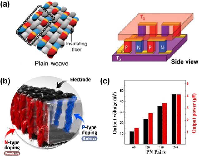
Figure 4. (d) the plain weave structure of TEG-HBBT along with (b) the side view of the TEG-HBBT structure, showing the thermocouples array connection. Reproduced with permission from Ref. 119. Copyright 2016 Wiley-VCH. (c) CNT-coated yarn-based TEG-HBBT doped with PEI (n-type) and FeCl3 (p-types). (d) Energy harvesting performance output of the TEG-HBBT at different number of PN pairs. Adapted with permission from Ref. 62. Copyright 2017 American Chemical Society.
Download figure:
Standard image High-resolution imageWith the advancement of materials and fabrication technology, high ZT values of TEGs can also be achieved at low-temperature operation (300–400 K). 117 Moreover, unlike the TENGs, the TEGs generate DC voltage and current, and thus there is no need for additional circuitry to harness the electrical energy output of the TEGs. Furthermore, being able to utilize the energy from a small temperature difference between body and ambient temperature, the TEGs have recently emerged as one of the promising energy source modules for body-powered biosensing textiles. The typical maximum output power generated by the TEG-based HBBT system (TEG-HBBT) is in the nW scale. However, with novel materials and fabrication engineering methods, the maximum output power could be enhanced up to tens of μW.
In general, the TE materials used in TEG-HBBT can be categorized into two major types, i.e., inorganic 118,119 and organic TE materials, including the thermo-conductive polymers 42,120 and the carbon-based materials. 121–123 Typically, the inorganic TE materials have higher conversion efficiency than the organic ones. However, their deposition process is rather complex, and most of them require a piece of vacuum equipment and/or high-temperature processes. Meanwhile, organic TE materials are preferred because of their low-cost and low-temperature fabrication processes and higher mechanical flexibility. A high TEG-HBBT output power generation was reported by T. Zhang et al. using inorganic TE materials. 124 Using a thermal drawing process, they fabricated TE fibers made from Bi0.5Sb1.5Te3 for the p-type and Bi2Se3 for the n-type. Despite the typical brittleness of inorganic materials, these fibers could endure a mechanical bending at relatively small bending radii depending on the diameter of the fibers. With a diameter of less than 50 μm, the fibers could endure a bending radius of less than 1 cm. The fibers could produce a high output power of 1.65 μW with an output voltage of 97 mV and the corresponding output power density of 2.34 mW cm−2 at ΔT = 60 K, which was almost similar to a 2D film of TE materials deposited by a screen printing or painting method. 125 Furthermore, the authors also demonstrated that the TE fibers could be used as a power generator, and as a wearable cooling fabric. In another report from J. Choi et al., a high output power TEG-HBBT was demonstrated by using a combination of inorganic and organic TE materials via a doping strategy, in which carbon nanotube yarn (CNTY) was doped with polyethyleneimine and FeCl3 for the n- and p-types, respectively, 62 as shown in Fig. 4b. Owing to a high specific electrical conductivity (103 S cm2 g−1), the CNTY also worked as the electrode of the BT-TEG system while omitting the need for a metal electrode. The CNTY was wound around a 4 × 10 × 80 mm3 polydimethylsiloxane (PDMS) supporting unit to form 60 pairs of p- and n-types thermocouples. One major achievement of this work was the high output power at a small temperature difference, which is demanded wearable application. At ΔT of only 5 K, their 60-pairs CNTY delivered output voltage of ∼13 mV and an output power of 1.5 μW. As shown in Fig. 4c, increasing the number of pairs into 240-pairs could significantly improve the output voltage and power to 47 mV and 4.2 μW, respectively.
Biofuel cell-based HBBT (BFC-HBBT)
In principle, BFC is a fuel cell that produces electricity based on a biocatalysis process, which is typically enzyme-based. Furthermore, there are two types of BFC based on the electron transfer, i.e., the direct and mediated electron transfer. The BFC system is commonly a direct BFC type for wearable applications, which means the system does not need an additional inorganic catalyst to produce electricity. Instead, the biocatalyst itself is involved in the redox reaction. A BFC system's most common and simple configuration uses glucose as the fuel with glucose oxidase (GOx) or glucose dehydrogenase (GDH) enzyme immobilized on the anode electrode to oxidize the glucose fuel and generate electrons simultaneously. These electrons will flow through the external circuitry and reach the cathode electrode. Further, bilirubin oxidase (BOx) or (BOD) is immobilized on the cathode electrode to reduce the oxygen from ambient into the water utilizing the protons and electrons (produced at the anode). As a result, as long as the glucose fuel is present, a continuous current flow can be observed. 34 Therefore, BFC can be used both as an energy harvesting system and a self-powered sensing system, as illustrated in Fig. 5a.

Figure 5. (a) Basic energy harvesting and self-powered sensing principle of a BFC system using glucose fuel. Reproduced with permission from Ref. 34. Copyright 2019 Wiley-VCH. (b) High power BFC-HBBT on textile cloth using a multilayer of GDH/A-CNT/PolyMG/A-CNT/carbon fiber (bioanode) and PTFE-CNT/BOD/A-CNT/PTFE-CNT/carbon fiber (biocathode). (c) Energy harvesting performance output of the BFC-HBBT at different number of BFC cells connected in series. Adapted from Ref. 67. Copyright 2019, with permission from Elsevier.
Download figure:
Standard image High-resolution imageOnce any biological component is involved in the system, the universal characterization of the BFC performance or the figure of merit becomes more complex. There are various factors to be considered, i.e., the specific surface area of the electrodes, the mass quantity of the fuel and the enzyme dimension, coverage, reactivity on the electrode surface, and the stability of the redox reactions over time, which each of these factors might vary between BFCs. 126 Therefore, the performance of BFCs is generally determined by the measurement of its VOC, peak oxidation/reduction current, and power density output. Theoretically, the VOC of a BFC can be calculated using the Nernst equation. 127 However, the measured VOC is typically lower than the theoretical calculation. This is due to at least three factors: overall system resistance, mass transport limitation of the reactant, and the specific kinetics at the electrode/electrolyte interface. 128
Nevertheless, BFC still becomes an emergent research topic to realize self-powered biosensing devices since the utilized biofuels are mostly the same bioanalytes that a biosensor must detect. The biosensing properties of a BFC, including the BFC-HBBTs, heavily rely on the enzyme receptor, and thus the current BFC-HBBTs are still based on glucose 67,89,129 or lactate fuels. 130,131 It is worth mentioning that by utilizing a lithography patterning method and a 3D CNT-based bioanode and biocathode array, A.J. Bandodkar and co-workers were able to realize a high-power-output wearable BFC as high as 1 mW by scavenging the lactate from the human sweat and simultaneously power-on a LED or a BLE radio. 132 The first wearable BFC system to power a BLE radio is described in the literature. In search of BFC-HBBT with a high power density output, C.H. Kwon and co-workers proposed a porous metallic (AuNPs) cotton fiber-based BFC (MCF-BFC), which was fabricated using a layer-by-layer (LbL) assembly. 133 In detail, for the biocathode electrode, the tris-(2-aminoethyl)amine (TREN) layer was covalently assembled onto the tetraoctylammonium bromide-stabilized Au NPs (TOA-AuNPs) layer and coated into the cotton fibers. For the bioanode electrode, the GOx was electrostatically assembled onto TOA-AuNPs/TREN multilayer and coated on the cotton fibers. As a result, using a 120-bilayer MCF cathode and 30-bilayer GOx/20-bilayer MCF anode, a maximum power density output of 3.7 mW cm−2 in 300 mmol/l glucose was achieved. Similarly, using a fiber-based BT-BFC, S. Yin and co-workers developed an enzyme/carbon-based fiber, for both the bioanode and the biocathode, along with ionic isolation to realize glucose-powered BFC-HBBT fibers on the textile cloth. 67 The bioanode fiber was a multi-layer fiber consisting of GDH/acid treated-CNT/polymethylene green/acid treated-CNT/carbon fiber (GDH/A-CNT/PolyMG/A-CNT/carbon fiber), while the biocathode fiber was also a multi-layer fiber-based, which comprised of PTFE-CNT/BOD/A-CNT/PTFE-CNT/carbon fiber, as shown in Fig. 5b. Both bioanode and biocathode were combined to build a BFC, which yielded a maximum power density of 216 μW cm−2 at 0.36 V in 200 mM glucose and 10 mM NAD+. Furthermore, by using an ionic isolation technique, they could realize a series connection of 4-cell BFC-HBBT fibers to increase the fibers' VOC and maximum power to 1.9 V and 0.38 mW, respectively, as shown in Fig. 5c. As a result, an LED lit up upon dropping a solution containing 200 mM glucose and 10 mM NAD+. Another remarkable progress on the development of BFC-HBBT was reported by J. Lv and co-workers, 131 who demonstrated a stretchable screen-printed BFC-HBBT integrated with a supercapacitor (SC). Engineering inks with high plasticity realized the stretchability, i.e., Ag-SIS (stretchable wiring ink), CNT-PU (stretchable electrode ink), and MnO2-CNT/CNT/PEDOT:PSS (stretchable SC ink). With a serpentine-shaped electrode pattern, both SC and BFC-HBBT exhibited a mechanical resiliency under bending, twisting, or stretching. The maximum area power density of the printed SC and BFC-HBBT was 4000 mW m−2 and 2520 mW m−2, respectively. Furthermore, the wearable BFC-HBBT was realized by printing three-series SCs and five-series BFCs, connected in parallel, on an armband. Upon a volunteer exercising and perspiring for 37 min, the SC was charged up to 0.4 V, maintaining stability for at least 15 min.
Hybrid nanogenerator-based HBBT (HNG-HBBT)
All the previously discussed energy-harvesting strategies produce different power density outputs. For example, the TENG-HBBT could achieve a power density output as high as a W/m2, while the TEG-HBBT is typically below hundreds of mW m−2. For future HBBTs applications, the smart textiles should collect as many biosignals as possible and generate enough energy for the data transmission and/or for the alerting system simultaneously. Therefore, the concept of HNG might become a key technology. Due to its high electrical output, TENG is a widely used concept for any nanogenerator combination in HNGs. In general, the TENG-based wearable HNGs can be categorized into two groups: AC-AC TENG-HNGs and AC-DC TENG-HNGs. 134 For AC-AC TENG-HNGs, the nanogenerators could combine TENG-PENG, 135–137 TENG-electromagnetic generator (TENG-EMG), 138–140 or TENG-PENG-pyroelectric nanogenerator (TENG-PENG-PyNG). 141–143 In contrast, for AC-DC TENG-HNGs, the combination could be TENG-solar cell (TENG-SC) 144,145 or TENG-TEG. 146,147
For applications in biosensing textiles, the studies on HNG are still in an early stage. Particularly for the application in HBBT, almost all of them are based on TENG-PENG. The primary mechanism of biosensing textiles based on TENG-PENG HNG (TPH-HBBT) was well elaborated by Y. Guo and co-workers. 148 In their work, the TPH-HBBT consisted of silk fibroin and electrospun-PVDF fibers sandwiched in between two conducting fabrics, as shown in Fig. 6b. The PVDF fibers, besides being a triboelectric pair with the silk fibroin, also enhanced the overall charge generation and transfer due to additional piezoelectric charges, which they produced upon applying an external force. Hence, the working principle of the BT-TPH, as illustrated in Fig. 6a, could be briefly explained as follows: In their original state, the system is electrically neutral. In the contact state, net positive charges at the silk fibroin surface and net negative charges at the PVDF fibers surface are formed due to the triboelectric effect. A built-in piezoelectric potential is developed in the deformation state as the PVDF fibers experience mechanical stress. Consequently, the electrons flow from the top to the bottom electrode. The electrons flow back as the built-in piezoelectric potential decreases in the recovery state. In the separation state, electrons flow back from the bottom to the top electrode as the contact triboelectrification diminishes.
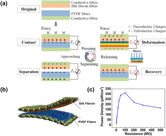
Figure 6. (a) Basic working mechanism of the TENG-PENG based HNG-HBBT. Adapted from Ref. 148. Copyright 2018, with permission from Elsevier. (b) All-fiber TPH-HBBT consisted of silk fibroin fibers (triboelectric) and PVDF fibers (triboelectric/piezoelectric) sandwiched in between conductive fabrics. (c) Energy harvesting performance output of the BFC-HBBT by varying the load resistance. Adapted from Ref. 148. Copyright 2018, with permission from Elsevier.
Download figure:
Standard image High-resolution imageFurthermore, they also found that the polarization direction of the PVDF crucially determines the electrospinning voltage direction. The TPH-HBBT will work synergistically by enlarging its electrical outputs when it works in the "accordant state," i.e., the triboelectric and piezoelectric currents are in the same direction. The TPH-HBBT exhibited a very high power density output as high as 3.1 W m−2 at 100 MΩ, as shown in Fig. 6c, with a VOC (max) of 500 V and ISC(max) of 12 μA. Moreover, they also developed an automatic falling detection system by connecting the TPH-HBBT with a microcantilever. Upon giving a high impact to the TPH-HBBT (simulating the falling scenario), the microcantilever was pulled downwards, such that the signal processing system was triggered to send a SOS message to remote devices. Instead of using 2 electrodes, J. Song and co-workers developed a high power density output TPH-HBBT using a 3-electrode configuration (TPH3E). 149 The TPH3E comprised a cascaded PENG and TENG units, where the piezoelectric and triboelectric material was made from electrospun PVDF/CNT/BaTiO3 composite films and a micropatterned-rough surface of a PDMS/CNT/graphene composite film, respectively. Three conducting fabrics at the top, bottom, and between the PENG and TENG completed the TPH3E structure. The device exhibited a power density output of 2.22 W m−2 at 20 MΩ with a VOC (max) of 161.66 V. By integrating this TPH3E into gloves, shoes, trousers, coats, it monitored various biomotions such as hand clapping, walking (footsteps), and patting. Furthermore, we also provide a performance comparison of all energy harvesting strategies in Table III. The comparison items include the active materials, the electrical outputs, the physical/biosignal monitoring, and the power generation capability.
Table III. Performance comparison of body-powered biosensing textiles with different energy harvesting strategies.
| Energy harvesting Strategy | Elemental classification | Active materials | Electrical outputs | Physical/biosignal monitoring | Power supply capability | References |
|---|---|---|---|---|---|---|
| PENG | Fiber-based | Pt-PVDF NFs | 6 mA | Muscle activities (speech, cough, swallowing), pulse pressure waves (PPW), heart rate | 100 lEDs, digital calculator(via 1 μF capacitor) | 97 |
| 30 V | ||||||
| 22 μW cm−2 (1 MΩ load) | ||||||
| Sugar-encapsulated PVDF nanofiber webs (SGNFW) | 100 V | Tactile touch, body vibration | LEDs, LCD screen (via 1 μF capacitor) | 109 | ||
| 3.3 μW cm−2 | ||||||
| (15 MΩ load) | ||||||
| Microstructured Pdop-BaTiO3@ P(VDF-TrFE) NF | 1.05 uA | body movement (squatting, walking, running), elbow movement, finger motions | 110 | |||
| 5.24 V | ||||||
| 0.88 μW cm−2 | ||||||
| (5 MΩ load) | ||||||
| PVDF/BT fiber | 4 V | full body movement (walking, running), finger motions | Capacitor charging | 247 | ||
| 87 μW cm−3 | ||||||
| PVDF/Fe-ZnO fiber | 12 V | tactile touch, elbow and shoulder joints movement | 245 | |||
| 87 μW cm−3 | ||||||
| (1 MΩ load) | ||||||
| TENG | Fiber-based | CNT-PEI fibers and PTFE | 12.6 μA | Tactile touch, foot steps | 89 lEDs, pedometer, watch, calculator, timer | 248 |
| 119 V | ||||||
| 0.32 μW cm−2 | ||||||
| (5 MΩ load) | ||||||
| Fabric-based | Ni-polyester and silicon rubber | 140 μA | Joints movement (elbow, knee), walking, running | 100 lEDs, digital timer, calculator, digital clock | 115 | |
| 540 V | ||||||
| 892 μW cm−2 | ||||||
| (10 MΩ load) | ||||||
| Nylon fabric and oblique PDMS microrod arrays | 51.84 μA | Elbow joint movement | 48 lEDs | 116 | ||
| 1014.2 V | ||||||
| 211.7 μW cm−2 | ||||||
| (6 MΩ load) | ||||||
| (cotton/spandex/wool) fabric and PTFE | 80 μA | arm movement and walking | LED, controlling music player (start/stop and volume level) | 249 | ||
| 300 V | ||||||
| 600 μW cm−2 | ||||||
| (1 MΩ load) | ||||||
| F-TENG (top): parylene-Ni polyester fabric r | 15 μA | tactile touch, elbow and shoulder movement | 54 lEDs, digital calculator (via 33 μF capacitor) | 250 | ||
| 120 V | ||||||
| 50 μW cm−2 | ||||||
| CS-TENG (bottom): Ni-polyester parylene-Ni on polyeste | (10 MΩ load) | |||||
| TEG | Fiber-based | Bi2Se3 microfiber (n-type) Bi0.5Sb1.5Te3 microfiber (p-type) | 97 mV | body surface temperature, temperature control (cooling fabric) | 124 | |
| 0.23 μW cm−2 | ||||||
| (ΔT = 60 K) | ||||||
| PEI/CNT yarn (n-type) FeCl3/CNT yarn (p-type) | 47 mV | body surface temperature | LED | 62 | ||
| 4.2 μW | ||||||
| (ΔT = 5 K) | ||||||
| PEI/CNT yarn (n-type) | ∼402 μA | body surface temperature | digital thermometer, pedometer, UV detector (via a supercapacitor) | 122 | ||
| ∼4 mV | ||||||
| PEDOT:PSS/CNT yarn (p-type) | 5.15 μW cm−2 | |||||
| (ΔT = 47.5 K) | ||||||
| oleamine/CNT fiber (n-type) PEDOT:PSS/CNT fiber (p-type) | 700 μA | body surface temperature | 121 | |||
| ∼26 mV | ||||||
| 7 μW cm−2 | ||||||
| (ΔT = 44 K) | ||||||
| Fabric-based | Sb2Te3 (n-type) | ∼10 mV | body surface temperature | 118 | ||
| Bi2Te3 (p-type) | ∼1 nW cm−2 | |||||
| BFC | Fiber-based | MCF with GOx (bioanode) | ∼0.9 V | Glucose concentration | 133 | |
| MCF (biocathode) | 3700 μW cm−2 | |||||
| (300 mM glucose) | ||||||
| MWCNT/PolyMG carbon fibers with GDH (bioanode) MWCNT carbon fibers with BOx (biocathode) | 0.51 V | Glucose concentration | LED | 67 | ||
| 216 μW cm−2 | ||||||
| (200 mM glucose) | ||||||
| Fabric-based | MgOC-CC with LOx/1-methoxy PMS (bioanode) MgOC-CC-PTFE with BOx/ABTS (biocathode) | ∼0.8 V | Lactate concentration | 130 | ||
| 4300 μW cm−2 | ||||||
| (300 mM lactate) | ||||||
| NQ/CNT with LOx (bioanode) Ag2O/CNT (biocathode) | 0.49 V 252 μW cm−2 | Lactate concentration | 3 lEDs | 131 | ||
| (15 mM lactate) | ||||||
| CNT/NQ with LOx or GOx (bioanode) Ag2O/Ag (biocathode) | 0.44 V | Glucose or lactate concentration | 6 lEDs | 89 | ||
| 160 μW cm−2 | ||||||
| (50 mM glucose) | ||||||
| 250 μW cm−2 | ||||||
| (20 mM lactate) | ||||||
| HNG | Fiber-based | Silk fibroin fibers PVDF fibers | 12 μA | Elbow bending angles, falling detection | 2 lCDs (without capacitor) | 148 |
| 500 V | ||||||
| 310 μW cm−2 | ||||||
| (100 MΩ load) | ||||||
| Fabric-based | PVDF/CNT/BaTiO3 composite film (piezoelectric) PDMS/CNT/graphene composite film (triboelectric) | 161.66 V | Hand clapping, walking (footsteps) | 150 lEDs | 149 | |
| 222 μW cm−2 | ||||||
| (20 MΩ load) | ||||||
| PTFE-silicon rubber (triboelectric) PZT (piezoelectric) | 17 μA 600 V | walking | 120 lEDs calculator, digital thermometer, watch (all via a capacitor) | 251 | ||
| 111 μW cm−2 | ||||||
| (20 MΩ load) |
Biomonitoring Applications of the HBBTs
Active motion monitoring
Most of the active motion monitoring HBBTs are based on the TENG or PENG principles and, in general, can be classified into several groups of applications, including joint motion, 45,150–152 finger motions or hand gestures, 153–157 as well as gait monitoring/foot motions (walking, running, standing, and jumping). 154,158–161 Human gait monitoring is one of the most-studied topics for clinical purposes since it could reflect the pathology of various neurological, muscular, or skeletal disorders and could also be used for physical rehabilitation monitoring. 162,163 Numerous works have been proposed to realize TENG-HBBT or PENG-HBBT based gait monitoring textiles, and most of the proposed works are related to TENG-HBBT or PENG-HBBT based socks/insole. 110,111,164–167
X. Guan and co-workers proposed a nanocomposite PENG-HBBT insole for gait monitoring. 110 They developed a piezoelectric material made of polydopamine modified barium titanate (Pdop-BT) nanoparticles decorated on the surface of P(VDF-TrFE) fibers [Pdop-BT@P(VDF-TrFE) nanocomposite]. The nanocomposite PENG-HBBT was realized by sandwiching the Pdop-BT@P(VDF-TrFE) nanocomposite between Cu-Ni conductive fabrics. The nanocomposite exhibited 4.4 times higher output voltage compared to pristine P(VDF-TrFE) along with an applied force up to 700 N. This nanocomposite PENG-HBBT was then integrated into an insole to perform gait monitoring, including normal walking, running, and squatting up or down. On the contrary, by utilizing the triboelectric system, Z. Zhang and co-workers proposed washable TENG-HBBT socks for real-time gait monitoring. 111 The washable TENG-HBBT socks were made of nitrile thin films and the frustum-shape silicon rubber films as the triboelectric materials, conductive textiles as the charge collection layers, and the non-conductive textile layers at the top and bottom surface for device encapsulation. The frustum structure allowed for larger triboelectrification contact areas. A high-pressure sensitivity of 1.2 V/kPa (at 10–70 kPa pressure range) and an extensive pressure sensing range up to 244 kPa were achieved. These frustum-shape TENG-HBBT socks were then utilized to monitor various gait patterns, including normal walking and abnormal gait (loss of stride/LOS and freezing of gait/FOG), associated with the onset of Parkinson's disease. In addition to gait monitoring, joint monitoring could also provide important health information, knowing that arthritis—a musculoskeletal disorder - has become one of the significant health issues in the world for ageing people. 168 To Address the need for joint tracking, L. Liu and co-workers proposed a nanowrinkled TENG-HBBT for joint monitoring, i.e., knee bending angle monitoring. 169 The nanowrinkle structure was based on a nanowrinkled-PDMS/PVDF composite film (NW-PPCF) and was made into TENG-HBBT by weaving the warp yarn of the sandwich structure of NW-PPCF/Ag fabric/NW-PPCF and the weft yarn made of Ag fabric, as shown in Fig. 7a. The nanowrinkle structure allowed a high electrical output (Voc of 255 V and Isc of 22 μA at 50 MΩ of external load) and a robust cyclic pressure impact up to 2200 cycles. As a result, the nanowrinkled TENG-HBBT was able to monitor the knee movement angle from 15° to 70°, as shown in Fig. 7b.
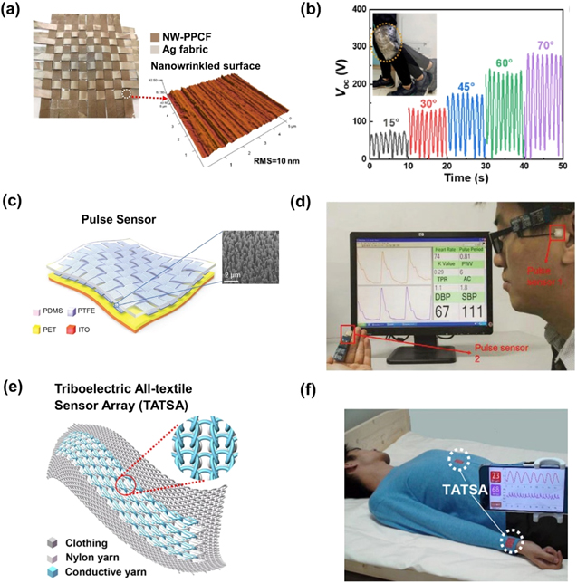
Figure 7. Biomonitoring applications of the HBBTs. (a) A woven TENG-HBBT based on a nanowrinkled-PDMS/PVDF composite film for (b) knee bending angle monitoring. Adapted from Ref. 169. Copyright 2020 with permission from Elsevier. (c) Flexible WCSPS TENG-HBBT made of woven PTFE-nanowires and a planar PET film for body PP sensing along with for (d) a continuous cuff-less BP monitoring. Reproduced with permission from Ref. 15. Copyright 2018 Wiley-VCH. (e) Knitted TENG-HBBT based on conductive terylene and nylon yarns for f) respiration and body PP signals monitoring. Reproduced with permission from Ref. 175. Copyright 2020 Science Advances.
Download figure:
Standard image High-resolution imageBody pulse wave sensing (BPW)
Among many biosensing applications of HBBTs, PW sensing is a widely used biosensing principle that provides an abundance of health information, where a particular set of PW data can be utilized to realize different biosensing applications. In general, the primary biosensing application of the PW sensing is for cardiovascular health monitoring, for example, the heart rate (HR) monitoring. 68,170 Several works have been proposed to extend the PW to the PP signal sensing. 43,171–173 The PP signal contains a lot more information than only HR. First of all, the augmentation index (AI), which is an age-dependent vascular aging parameter, correlates well to the premature coronary artery disease, 174 and is calculated from the ratio between the first and the second systolic peak of the PP signal. Secondly, by simultaneously recording PP signals at two different body sites, a pulse wave velocity (PWV) can be calculated, 175 which can be used to assess the aortic arterial stiffness. 176 Thirdly, it provides blood pressure (BP) estimation. Noting that the high BP or hypertension could be lethal or induce serious complications, such as heart failure, coronary artery disease or stroke, it becomes critical to realize a device or system that could continuously and comfortably monitor BP. 177,178
K. Meng and co-workers proposed a flexible weaving constructed self-powered pressure sensor (WCSPS) for cardiovascular health monitoring, including the cuff-less blood pressure (BP) monitoring. 15 The WCSPS was based on TENG-HBBT, which comprised PET and interlaced woven PTFE as the triboelectric pair and a thin-film ITO as the back electrode. Besides, vertical nanowires were also formed on the back surface of the PTFE to increase the triboelectrification contact area, as shown in Fig. 7c. Hence, with the structure of this material, the WCSPS exhibited a sensitivity of 45.7 mV Pa−1 at below 0.71 kPa region with a minimum detectable pressure of 2.5 Pa, which was considered small enough that it could detect a human hair with the weight of only 5 mg. With these excellent pressure-sensing characteristics, the WCSPS detected the pulse pressure (PP) at various body sites, including at the wrist, ankle, ear, and even at the fingertips. Furthermore, by measuring the pulse transit time (PTT) between the PP peak from the fingertip and ear, they realized a cuff-less BP monitoring based on the Moens-Korteweg equation principle. 179 In addition, by integrating an embedded wireless system and a mobile app, the cardiovascular health parameters could be displayed in the smartphone in real-time, as shown in Fig. 7d. They also measured the artery compliance (AC), peripheral resistance (PR), and BP of 100 participants with the known cardiovascular health condition. The results showed that the total peripheral resistance (TPR) and the AC values well complied with the known patient's cardiovascular health condition. A high TPR and a low AC correlated to hypertension and vice versa.
Moreover, a flower-shaped superstructure textile-based sensor (FSTS) system for continuous on-body biomonitoring with wearing comfort and art design was proposed by K. Meng et al. 180 The FSTS could capture body PP signal based on the TENG principle using a two-layer textile configuration, i.e., a silver-coated polyester fabric as the base and a 3-ply-twisted polyester-metal hybrid fiber as the flower-shape superstructure. They both played a dual role, i.e., the triboelectric couple layer and the electrode. The FSTS exhibited a sensitivity of 3.88 V kPa−1 at a pressure range of 0.1–4.3 kPa. Moreover, the FSTS also demonstrated a stable output performance even under ambient chemical disturbance, i.e., the humidity variation condition and the corrosion caused by the sweat. For PP sensing applications, the FSTS was sewn on the clothes/textiles and was used to evaluate the AI value of an older woman (75-year-old) and a young woman (22-year-old) in a 12 h continuous recording manner. The result showed that the young woman had a lower AI value than the older woman, which correlated with the more elastic vascular properties of the younger woman.
Respiration monitoring
The respiration rate (RR) parameter is vital in respiration monitoring applications because it can reflect how well the human body controls the homeostatic body. 181 Besides, RR is also sensitive towards changes in pathological body conditions, such as infection, respiratory tract diseases, mental condition, and fatigue. 182 Thus, monitoring of the RR has an essential role in recognizing early signs of clinical deterioration, which might lead to severe illnesses, or in measuring athletes' training intensity. The self-powered systems to realize a real-time tracking of the RR is mainly based on TENG. 183–188 In general, there are two methods of using TENG to monitor the RR: Sensing the subtle body motion from the chest and abdominal cavity movement 183,185 and sensing the laminar airflow blown from the nose or mouth during breathing. 189–191 The second method might provide more comfort to wear since it can be installed on a facemask. Furthermore, by implementing the TENG-HBBT concept, more physiological signals could be probed. For example, besides detecting each inhalation and exhalation from the breathing cycle, the heartbeat signal and possibly the sleep monitoring could also be monitored. 175,187,192,193
Zhao and co-workers proposed a woven TENG-HBBT, which consisted of Cu-PET warp yarns and PI-Cu-PET weft yarns. 193 These were integrated into a chest strap to measure the RR and the respiratory depth. The woven TENG-HBBT could sense a real-time respiratory pattern for four breathing states. i.e., the deep breathing (tidal volume was 2946 ml), the shallow breathing (tidal volume was 976 ml), the rapid breathing (RR was 75 breaths min−1), and the slow breathing (RR was 26 breaths min−1). Additionally, the woven TENG-HBBT was also durable even after 20 times of washing.
Similarly, Fan and co-workers reported a TENG-HBBT sensor array using conductive one-ply terylene yarns twisted around stainless steel and nylon yarns, 175 as shown in Fig. 7e. All yarns were knitted in a white elastic chest strap to measure the respiratory signal. Triboelectrification and electrostatic induction were generated by the contact-separation dynamics between the nylon and the conductive yarns. The TENG-HBBT sensor array exhibited a pressure sensitivity of 7.84 mV Pa−1 at below 4 kPa pressure region, a response time of 20 ms, a mechanical resiliency of more than 100,000 pressure load cycles, and washing durability of more than 40 times. Furthermore, a wireless mobile health monitoring system (WMHMS) was also developed to wirelessly send two physiological data (respiratory and heartbeat signals), as shown in Fig. 7f. In the other work, He and co-workers proposed a face mask TENG-HBBT for breath monitoring. 189 In detail, it was based on a hierarchical nanostructure of 2D cellulose microfibers (CMFs), cellulose nanofibers (CNFs), and an Ag nanofiber membrane. Fluorinated ethylene propylene (FEP) film was laminated at the bottom side and was used as a counter tribo-material to the CMFs/CNFs. The face mask TENG-HBBT was used to monitor the breathing rate during normal (15 breath min−1) and after running (45 breath min−1).
Sleep monitoring
Sleep quality has been associated with several high-risk diseases, especially cardiovascular diseases. 194–196 The current established method to evaluate sleep quality is using polysomnography (PSG). 197,198 However, this method uses several electrodes and sensors attached to the body, which causing discomfort during sleeping. Thus, for this particular issue, besides the commercial wearable devices such as the smart bracelet, 199,200 HBBTs are also a highly desirable option since it allows seamless body movement and bio-signals detection during sleeping by the use of the commonly worn textile. The widely used HBBTs for sleep monitoring are based on the TENG-HBBT principle. 175,180,187,192,201 In general, there are three methods in monitoring sleep using BT-TENG, i.e., sleep position monitoring, sleep apnea diagnosis, and the combination of the preceding two methods.
Lin and co-workers proposed a washable and large-area TENG-HBBT based smart bedsheet for sleep position monitoring. 201 Ag-coated conductive textile fibers were laminated on each sheet and aligned in a perpendicular row-column array, which was periodically separated by wavy-shaped PET films to form a triboelectric system in a two-layer sandwich bedsheet, as shown in Fig. 8a. This wavy-shaped structure could achieve high sensitivity of 0.77 V Pa−1 at an applied pressure below 6 kPa and a less than 80 ms response time. As a result, they could continuously monitor the full-body position during sleeping overnight and lit up an alarm when the sleep position was at the edge of the bed (falling prevention), as shown in Fig. 8b. Additionally, the washability of the smart bedsheet was also demonstrated by showcasing the negligible change of resistance and output voltage after washing them in tap water. With a similar concept, a multi-modal bio-signal measurement system using a washable TENG-HBBT bedsheet for sleep position monitoring and sleep apnea diagnosis was recently reported by Z. Zhou and co-workers. 187 The washable TENG-HBBT bedsheet was made of a serpentine weaving array of sheath-core structure fibers, comprised a hollow silicone fiber as the outer sheath and a polyester yarn twisted on the stainless-steel rod as the inner core. The triboelectric charges were exchanged between the silicon fiber and the twisted polyester yarn when an external pressure was applied to the fibers. The fibers exhibited a pressure sensitivity of 10.79 mV Pa−1 at pressure range of 0–2 kPa and a stable voltage output under an applied pressure frequency variation (0–40 Hz). By aligning the fiber array within the back chest area of the patient, the TENG-HBBT bedsheet was able to continuously monitor the sleep position and physiological signals (respiration and heartbeat) simultaneously. The TENG-HBBT bedsheet detected obstructive sleep apnea-hypopnea syndrome (OSAHS) from an actual patient with a further signal processing algorithm. Furthermore, silicone as the outer sheath rendered the fibers water repellent. Additionally, the robust electrical output of the fibers from washing and human sweat or ambient humidity was showcased washing the fibers in the laundering machine and by soaking the fibers in artificial perspiration.

Figure 8. (d) Large-area TENG-HBBT bedsheet made of wavy PET and Ag-coated textiles for (b) sleep position monitoring and falling down (from the bed) detection. Reproduced with permission from Ref. 201. Copyright 2018 Wiley-VCH.
Download figure:
Standard image High-resolution imageSurface body temperature sensing
Within all the various physiological signals, the body temperature is indeed an important parameter, where an abnormal level could reflect or indicate fatal health problems, such as hypothermia, 202 exertional heat stroke (EHS), 203,204 type 2 diabetes mellitus, 205 sudden infant death (SID), 206 bacterial infection, 207 the current worldwide health concern, i.e., the virus infection, 208 or other metabolic disorders. 209 For EHS, SID, and metabolic disorders, there is a need for long-term and/or during sleeping body temperature monitoring. In this case, HBBTs are the most suitable option since they eliminate the need for a battery that may need to be replaced periodically and provide comfort to wear. Additionally, the TEG-HBBT could also act as a cooling fabric, 124,210 providing first aid for hyperthermia.
V. Shalini and co-workers proposed a nanostructured inorganic-based TEG-HBBT that could detect human surface body temperature variations while generating electrical power simultaneously. 211 The nanostructured TEG-HBBT was made of drop-casted Bi2Te3 nanowires on carbon fabric (BCCF) as the p-type TE and Ni-Cu fabric (BCNCF) n-type TE. In contrast, the Bi2Te3 nanowires were synthesized using a facile one-step hydrothermal method. Drop casting these Bi2Te3 nanowires on the fabrics generated a potential barrier (ΔE) for the electrons to flow with the electrical field gradient in BCNCF, which was higher than the one in BCCF. As a result, the Seebeck coefficient of BCNCF (16 μV K−1) was higher than that of BCCF (−3 μV K−1). For measuring the body temperature, the wearable TEG-HBBT was constructed from BCNCF and BCCF segments, which were cut into several strips and connected in series, then attached to an uncoated fabric. By placing the TEG-HBBT on the arm of 12 different persons, each having a different body temperature, the wearable TEG-HBBT was able to measure and distinguish the body temperature variations (303–312 K). Moreover, to show that the facile synthesis of TE thin films could be compatible for large-scale fabrication, M. Jung and co-workers proposed a facile stencil-printing technique to fabricate a large-area TEG-HBBT. 90 The TEG-HBBT was made of PEDOT:PSS (n-type) and AgNPs/graphene (p-type) printed on the elastic weft-knitted polyester/cotton textile. Using an elastic textile, the stencil-printed TEG-HBBT also showed a stretchable characteristic by enduring an 800-cycle of stretch with 20% strain with a voltage output drop of only 7%. Furthermore, the large-area TEG-HBBT was demonstrated by fabricating a 5 × 5 TEG array on the elastic textile, as shown in Fig. 9a. The large-area TEG-HBBT was able to map the temperature distribution and change in real-time upon a finger touch, as shown in Fig. 9b.

Figure 9. (a) Large-area printed TEG-HBBT made of PEDOT:PSS and AgNPs/graphene inks for (b) body surface temperature detection and tactile touch sensing. Adapted with permission from Ref. 90. Copyright 2018 Royal Society of Chemistry. (c) Stretchable BFC-HBBT socks made of serpentine-shape electrodes and elastic inks for (d) sweat lactate or glucose detection, measured in real-time during cycling exercise. Reproduced from Ref. 89. Copyright 2016 with permission from the Royal Society of Chemistry.
Download figure:
Standard image High-resolution image
Metabolites sensing
Metabolite sensing is defined as a method to monitor or evaluate the body health condition by detecting the number of metabolic reaction products such as lactate, glucose, and uric acid, 212 which are contained in the body fluids, i.e., sweat, 213,214 urine, 215,216 tears, 217 or saliva. 218,219 For instance, continuous glucose level monitoring from the body fluids using wearable devices could help diabetic patients obtain a more accurate treatment. Severe side effects of diabetes, such as blindness, cardiovascular diseases, or kidney damage, could be prevented. 220–222 It must be noted that placing the wearable metabolite biosensor in the correct sensing site, especially for sensing the metabolites contained in sweat, is crucial to avoid a false correlation with the actual body metabolism. 223 In addition, a blood sampling must be conducted at least once a week to re-calibrate the data for long-term sweat monitoring. 224 The biosensors are based on the BFC-HBBT principle in order to realize textile-based metabolite sensing systems. Furthermore, since the current BFC-HBBTs are enzyme-based, the metabolite sensing capability of the BFC-HBBTs strongly depends on the variant of the enzymes, which are currently either GOx/GDH (for glucose detection) or LOx (for lactate detection).
A highly stretchable BFC-HBBT for monitoring sweat metabolites was first demonstrated by I. Jeerapan and co-workers by formulating the plasticity of the inks and implementing a serpentine design of the electrodes. 89 In detail, the base bioanode electrode was made of CNT mixed with PU, while the base biocathode electrode and the interconnects were made of Ag/AgCl mixed with Ecoflex. The formulated inks and the serpentine patterns were printed on the stretchable textile (nylon-spandex) using the screen-printing method. A stretchable BFC-HBBT was realized by anodizing the Ag/AgCl to form an AgO2 layer as the biocathode and depositing NQ-LOx as the lactate detection or NQ-GOx the glucose detection bioanode, as shown in Fig. 9c. The stretchable BFC-HBBT exhibited a sensitivity of 3.14 μW cm−2mM−1 at 0–50 mM for glucose and 66.5 μA cm−2mM−1 at 0–20 mM for lactate. Furthermore, by exhibiting a maximum power density of 250 μW cm−2 from the lactate fuel, enduring a 100% strain for up to 150 cycles, and being integrated with a signal processing and Bluetooth module along with a smartphone app, the stretchable BFC-HBBT (placed on the socks) was able to monitor the lactate concentration of a person during cycling exercise and able to display the corresponding lactate concentration in the smartphone app in real-time, shown in Fig. 9d. Moreover, using a fiber-based BFC-HBBT, S. Yin and co-workers developed a high-power bracelet out of BFC-HBBT fibers that could power a digital wristwatch from the human lactate fuel. 225 The fibers comprised a multi-layer of LOx/osmium-based mediator/SWCNT/carbon fiber as the bioanode and a multi-layer of BOx/CNT/PTFE-SWCNT/CNT fiber as the biocathode. The BFC-HBBT fibers exhibited a lactate oxidation current density of 8.8 mA cm−2 in the presence of 20 mM lactate and oxygen reduction current density of −8.7 mA cm−2 in air. The bracelet BFC-HBBT fibers were realized by tying a series of six biocathode and bioanode fibers together with six equally spaced ionic gel-coated storage textiles in a round shape. When 20 mM (3 ml) lactate sweat, which was approximately equal to the human sweat secreted at light exercises condition, was dropped into a single cell, it generated a spontaneous power of 37 μW. The output power increased to 74 μW when the sweat volume was increased to 10 ml. Overall, all biosensing applications of the HBBTs published to date are provided in Table IV.
Table IV. Biosensing performance comparison from different types of HBBT.
| HBBT Type | Power Source | Materials | Biosignal monitoring | Sensing range/Sensitivity | Washability | References |
|---|---|---|---|---|---|---|
| PENG | Footsteps, joint movement, finger motion | Pdop-BaTiO3@ P(VDF-TrFE) NF (piezoelectric) Cu-Ni polyester fabric (electrode) | Gait (walking, running), elbow movement, finger motions | Sensing range: up to ∼1120 kPa | — | 110 |
| Joints movement | P(VDF-TrFE) fibers (piezoelectric) Cu-wire and Au/Cr thin film (electrode) | Joints movement (elbow, knee, hand) | Sensitivity: 60.82 mV N−1 (at 0.5–14 N) | Water rinsing | 81 | |
| Finger motion | PVDF-ZnO nanorod (piezoelectric) rGO@PET fabric (electrode) | Finger motions | Sensitivity: 620 mV kPa−1 (at 0–2.25 kPa) Sensing range: from 8.71 Pa | Washable PET fabric | 157 | |
| TENG | Footsteps | Nitrile film and frustum-shape silicon rubber (triboelectric) | Gait (normal walking, loss of stride, freezing of gait, and falling down) | Sensitivity: 1200 mV kPa−1 (at 10–70 kPa) | 6 times immersion | 111 |
| Cu-polyester textiles (electrode) | Sensing range: 10–300 kPa | |||||
| Joints movement (knee, elbow) | NW-PPCF/Ag fabric/NW-PPCF | Gait, knee bending angle (15°−70°) | Sensing range:from ∼9.6 kPa | — | 169 | |
| Body pulse wave | Nanowire-woven PTFE and PET (triboelectric)ITO (electrode) | PP signal, PWV, BP, AC, PR | Sensitivity:45.7 mV Pa−1 (at < 0.71 kPa) | — | 15 | |
| 10.6 mV Pa−1 (at > 0.71 kPa) | ||||||
| Body pulse wave | Ag coated-fabrics and twisted polyester yarn (triboelectric)Metal rod (electrode) | PP signal, HR, AI | Sensitivity: 3.88 V kPa−1 (at 0.1–4.3 kPa) | — | 180 | |
| Chest movement (breathing) | Cu-PET (warp) PI-Cu-PET (weft) | Respiration rate, respiration depth/tidal volume | — | 20 washing times (laundering machine) | 193 | |
| Oral air flow (breathing) | CMFs/CNFs and FEP (triboelectric) Ag (electrode) | Respiration rate | Sensing range: 0.5–5 Hz (Repeated 3 mm displacement) | — | 189 | |
| Chest movement (breathing), Body pulse wave | Terylene yarn-stainless steel, nylon yarn (triboelectric/electrode) | Respiration rate, PP signal, AI, PWV, HR | Sensitivity: 7.84 mV Pa−1 (at < 4 kPa) | > 40 washing times (laundering machine) | 175 | |
| 0.31 mV Pa−1 (at > 4 kPa) | ||||||
| Full body movement | Wavy PET films, Ag-coated fabrics (triboelectric/electrode) | Sleep position monitoring | Sensing range: up to ∼14 kPa | tap water rinsing | 111 | |
| Sensitivity: 770 mV Pa−1 | ||||||
| Full body and back chest movement | Silicone fibers, polyester yarn (triboelectric) Stainless-steel rod (electrode) | Sleep position and OSAHS monitoring | Sensing range: up to ∼15 kPa | 8 washing times (laundering machine) | 169 | |
| Sensitivity: 10.79 mV Pa−1 | ||||||
| TEG | Body heat | Bi2Te3/carbon fabric (p-type) | Surface body temperature | Sensitivity: −2 to −3 μμV K−1 (p-type) | — | 211 |
| Bi2Te3/Ni-Cu fabric (n-type) | 15–16 μV K−1 (n-type) both at RT | |||||
| Body heat | PEDOT:PSS (p-type) AgNPs/grapheme (n-type) | Surface body temperature | Sensitivity: 10 μV K−1 at 373 K | — | 90 | |
| Body heat | PEDOT-Cl (p-type) Carbon fiber (n-type) | Surface body temperature | 16 μV K−1 at ΔT ∼ 4 K | Laundering in warm water | 64 | |
| BFC | Sweat glucose/lactate | CNT-PU/NQ-LOx or CNT-PU/NQ-GOx (bioanode) Ag/AgCl-Ecoflex/AgO2 (biocathode) | Lactate or glucose concentration | Sensitivity: 3.14 μW cm−2mM−1 (glucose) | — | 89 |
| 6.71 μW cm−2mM−1 (lactate) | ||||||
| Sensing range: 0–50 mM (glucose) | ||||||
| 0–20 mM (lactate) | ||||||
| Sweat glucose | GOx/Carbon fabric (bioanode) PB/Carbon fabric (biocathode) | Glucose concentration | Sensitivity:∼3.36 μW cm−2mM−1 | |||
| at 0.1–1000 mM glucose | 252 | |||||
| Sweat lactate | LOx/Osmium /SWCNT/carbon fiber (bioanode) BOx/CNT/PTFE-SWCNT/CNT fiber (biocathode) | Lactate concentration | Sensitivity: 2.08 μW cm−2mM−1 | — | 225 | |
| at 5–20 mM lactate |
Challenges and Future Perspectives
Many publications in the field demonstrate that biosensing textiles could be constructed as self-powered systems harnessing the power generated from our bodies, while simultaneously detecting and transmitting important biosignals. Moreover, depending on the application and the system design, the sources of energy produced by our body are at the same time the bio-target to be detected or monitored by the biosensing textiles. This means that an HBBT could provide both power generation and biosignal sensing, which could pave the way for the next generation of wearables/smart textiles. However, the research on HBBTs is currently still in its initial development stage. Therefore, some aspects could be explored and improved further to reach the maturity of this technology. Meanwhile, those aspects could also lead to the new opportunities or future directives of HBBTs, which in detail could be elaborated through optimizing the following elements:
Power storage
Printed batteries are decent candidates to as a power storage—alternative to the rigid and bulky conventional batteries—for e-textiles. Using the printing technology, the battery could be made ultrathin, flexible, lightweight, and low-cost with high areal capacity. Moreover, series of printed batteries can supply high DC-voltage/current for embedded electronics. The printing ink can also be selected according to the textile materials' roughness, flexibility, chemical compatibility, and thermal characteristics. For the materials, the lithium-ion 226,227 and zinc 228,229 –manganese dioxide batteries are the commonly used printed battery materials in this case.
The advantageous of Lithium-ion batteries (LIBs) are rechargeable, have a high energy density, and a longer discharge lifetime. But, they have limited capacity and a high mass per unit volume of electrode materials. Additionally, these batteries are extremely air and water sensitive. 230,231 Therefore, exposure to each of these environmental conditions is harmful to the safety and performance of batteries and eventually for the e-textiles themselves. Further, it also contains combustible liquid electrolytes, and the textile-based lithium batteries should not contain metallic current collectors and liquid electrolytes to be suitable for powering smart wearable and textile electronics.
On the other hand, Manganese oxide (MnO2)-based batteries are environmentally safe, inexpensive, unsolvable, and lightweight, and hence best suited for use in water-activated batteries. In addition, they are well-known for their long discharge cycle life, long storage time, and leakage-proof design. 232,233 Furthermore, supercapacitors have been utilized to store energy for textile-based electronics. Batteries are suitable for high-energy applications, but supercapacitors are best suited for high-power applications. They have high power density, high energy density, long cycle life, fast charge and discharge, instantaneous high current discharge, low cost, easy maintenance, and no pollution to the environment. Thus, with the further improvement of these printed batteries, the fully self-sustaining HBBT could be realized in the near future.
Wireless communication system integration
It has been demonstrated that HBBTs could generate a considerable amount of electrical power that can be utilized to power up small electronic devices. HBBTs could also be integrated with a capacitor to deliver more current output and to generate long-lasting electrical power. Then, the next challenge is to integrate HBBTs with a wireless communication system, realizing self-powered textiles for personalized remote health monitoring. Since the power generated by the HBBTs is very dynamic and highly depends on the person's condition/physical activities, it is required to design an efficient and robust power management system in the clothes. To reliably provide electrical power to the system and transmit the biosensing information of interest, one could combine several HBBTs by using one type of HBBT to generate the electrical power and another type of HBBT to sense the bio-signals. Another strategy is to implement a hybrid body-RF energy harvesting strategy. In this strategy, the electrical power could be fully harvested from an RFID/NFC signal, while the HBBT could be focused on generating self-powered bio-signal information. However, on top of all these topics, another main issue is implementing the system integration on the textiles, realizing a truly microgrids system. 234
Biocompatibility
Biocompatibility is a must property for any biomedical device. For biosensing textiles, the main concern is the compatibility of the devices with sweat. The biosensing textiles must not produce any leakage current when exposed to sweat since leakage current is dangerous and therefore must be avoided. Moreover, sweat may also induce skin irritation if the biosensing textiles do not facilitate sufficient skin breathing. Thus, the breathability of biosensing textiles becomes mandatory for practical use. Furthermore, the materials' toxicity and carcinogenicity must be taken into consideration. Especially the TEG-HBBT, it commonly uses CNTs as the base thermoelectric material. CNTs can enter the body through the respiratory system (inhalation and pharyngeal aspiration), digestive system (ingestion), dermal and ocular absorption (contact with skin and eyes), or by injection (blood circulation). 235 Acute and chronic inflammation, oxidative stress, granuloma formation, fibrosis, lung tumors, mesothelioma, and genotoxic effects in the lungs may be caused by airway exposure to CNTs and associated contaminants or catalytic materials that arise during production. 236 Activation of redox-sensitive transcription factors by dermal exposure to CNTs may lead to oxidative stress, free radical formation, and inflammation. 237 A variety of CNTs can enter living organisms via various routes and quickly enter the bloodstream, where they can cause a wide range of systemic toxicity. 238 Intranasal exposure of graphene oxide (GO) into the lungs might result in size-dependent lung damage. However, it was discovered that GO nanoparticles were harmless. 239
Long-term stability
Long-term stability is another crucial criterion for any biomedical device. Any HBBTs will be exposed at least with repeated mechanical strain/stress, compression forces, scratches, and sweat in a practical use case. Moreover, HBBTs may also expose to other external conditions, such as water drop/splash, humidity, and ambient temperature elevation. The effect of all these non-ideal conditions on the HBBTs performance must be thoroughly studied to gain the maturity of the technology. Several HBBTs show washing compatibility by enduring the soaking into a solution containing a detergent.
Moreover, since TENG-HBBTs can practically be constructed from any textile material, they possess excellent mechanical flexibility. However, those capabilities might not be the case for the other types of HBBT, especially for the TEG-HBBTs based on inorganic materials. Thus, innovative fabrication methods must be explored to enhance the mechanical flexibility of any type of biosensing textile. BFC-HBBT, in particular, commonly uses organic materials as part of its sensing element. Organic materials become unstable if exposed to temperature elevation, chemical solvents, light, and humidity. Hence, innovative encapsulation technology and materials engineering are crucial to realize long-term stable HBBTs. 240
Antibacterial system
Besides using conventional washing, integrating the textile with antibacterial systems could also help provide hygiene to the HBBTs. To realize such systems, the surface of fabrics/fibers is commonly functionalized with antibacterial agents, mainly inorganic compounds, such as nanostructured metals (Ag, Cu, and Te) or metal oxides (TiO2, ZnO, and CuO). 241,242 There might be a compatibility issue when incorporating/multilayering those compounds into/with the active materials in HBBTs. However, the electrically-stimulated antibacterial (ESA) system offers a flexible integration mechanism, which by the integration with HBBTs could pave the way for the realization of self-powered antibacterial systems. 243,244 The HBBT and the ESA system integration could be crucial, especially for BFC-HBBT since the HPPS for BFC-HBBT is obtained from sweat.
Integrated artificial intelligence for telemedicine
It has been extensively elaborated that the HBBTs can collect various biosignals in an active motion state or even during sleeping. Besides, since the power of an HBBTs system is self-sustained, they are capable of continuously monitoring the biosignals in a long-term duration, 24 h or more, by integrating a power management module in the system. This means that the dynamics of the biosignals data could be obtained. Depth analysis of one's health condition could be extracted by implementing a data classification using artificial intelligence. This could be useful, for example, for monitoring and analyzing one's gait patterns for neurological disorders assessment, for sleep quality and sleep apnea detection, for athlete's fitness endurance, and remote patient monitoring. It is also very beneficial for monitoring the patient's health condition during the pandemic (such as the Covid-19) and for the implementation of modern telemedicine, where the recorded data along with the classification results could be sent online, such that the medical doctors could assess the appropriate treatment/medication or suggest immediate actions in a faster and more accurate fashion.
Conclusions
In summary, the HBBTs pave the way for a new technology direction towards the next generation of self-powered wearable sensors/systems utilizing the human body as the source of energy and textiles as the base platform. The body energy that the HBBTs could harvest includes motion, pressure, body temperature, and sweat metabolites. It has been demonstrated that the power generated by HBBTs is considerably high and capable of supplying power to some electronic devices, such as a calculator, a digital clock, a digital thermometer, and an LCD. They can also even be used for controlling the sound level of a music device by harnessing the available power produced from our bodies. Moreover, the use of textile provides a wear comfort and an integration easiness with our daily clothes. Engineered biosensing fibers/yarns can be easily made/integrated into textiles by common industrial techniques, such as weaving, knitting, or braiding. A facile stencil- or screen-printing method can also be implemented on the textiles to fabricate HBBTs. Furthermore, using textiles, the implementation of self-powered multi-physiological signal monitoring systems on a single platform during active physical motion or even during sleeping becomes possible. For example, sleep monitoring can be extended to detecting of sleep apnea and the monitoring of the heart rate, respiratory signals, ballistocardiogram, and even the sleep position. Besides, the unique characteristic of HBBTs is that the physiological activities to be monitored are the source of electrical power themselves. Hence, together with the further development of the power management modules on textiles and antimicrobial and washability features, the HBBTs would promisingly create a new trend of self-sustained and body-powered wearables in the future.
Acknowledgments
The authors acknowledge financial grants provided by The Ministry of Education, Culture, Research, and Technology of The Republic of Indonesia under the grant scheme of Penelitian Dasar Unggulan Perguruan Tinggi (PDUPT) with the grant ID: 2/AMD/E1/KP.PTNBH/2020. Funding from the German side came from the KMU-innovative project 'Einzelpunkt-Sensorsystem für die nicht-invasive, dynamische Messung der Herzfunktion' of the Federal Ministry of Education and Research (BMBF) Germany (SINDynamik - FKZ: 13GW0180B). S.H. led the manuscript preparation, i.e., led the conceptualization, preparation, organization, and writing of the manuscript. M.E.H. shared the equal contribution, i.e., conceptualized, prepared, rewrote, and evaluated the manuscript, A.S.S., J.J., L.N.R., R.R.A., and L.U. wrote several parts of the manuscript. G.R. designed and polished the Figures. S.I. supervised, directed, and evaluated the manuscript content. I.A. and B.Y. supervised and evaluated the manuscript in overall.