

Abstract
Accurately quantifying applied potential is important to ensuring the comparability, accuracy, and precision of electrochemical studies. Reference electrodes (REs) enable knowledge/determination of the applied potential at electrodes in electrochemical systems. Ultimately, the choice of RE will depend on the particular requirements of a given electrochemical system, however, we note it is imperative to ensure the accuracy of the RE potential and its proper translation to a standardized scale. In this work, we highlight that while there are many commercially available REs, these must be experimentally calibrated to a reliable and practical standard potential scale, for instance the reversible hydrogen electrode (RHE) scale for aqueous systems. With representative data, we provide streamlined instructions on how to calibrate any RE to the RHE scale. We also provide guidance to mitigate and/or avoid possible electrolyte contamination issues arising from REs. Moreover, we offer a step-by-step guide on how to build a practical RHE RE, which may be a suitable and desirable option in certain applications. Our work emphasizes the need for the continuous adoption of standardized reference potential scales and demonstrates the versatility of the RHE scale, particularly in aqueous electrochemistry.
Export citation and abstract BibTeX RIS

This is an open access article distributed under the terms of the Creative Commons Attribution Non-Commercial No Derivatives 4.0 License (CC BY-NC-ND, http://creativecommons.org/licenses/by-nc-nd/4.0/), which permits non-commercial reuse, distribution, and reproduction in any medium, provided the original work is not changed in any way and is properly cited. For permission for commercial reuse, please email: permissions@ioppublishing.org.
The Need for a Reliable, Accurate, and Translatable Potential Scale
Electrochemical processes play important roles in a wide range of applications. For instance, electrochemistry has applications in stationary and mobile energy storage & conversion, 1–3 value-added chemical transformations, 4 resource recovery from waste streams, 5 chemical/biomolecular sensing, 6–8 etc. 9 Outside of applications such as batteries, which generally employ non-aqueous environments, 10,11 a substantial part of electrochemical processes are aqueous-based (e.g. most fuel cells/electrolyzers, bioelectrochemical processes, etc.). Key to understanding electrochemical processes is a proper measurement/knowledge of applied voltages (potentials) at the participating electrodes, i.e. the working electrode (WE) and counter electrode (CE) as opposed to only the potential difference (cell voltage) between the WE and CE.
In practice, the full/real cell voltage ( ) can be measured with a multimeter between the WE and CE. The theoretical standard cell voltage (
 ) can be calculated from thermodynamic data or from half-reaction standard reduction tables.
12
This calculated voltage would, however, be unable to disentangle contributions from kinetics and mass transport at the CE and/or WE. Therefore, a reference electrode (RE) is required to determine the potential being applied individually at the cathode and anode and needed to ultimately compare electrode potentials across electrochemical systems.
) can be calculated from thermodynamic data or from half-reaction standard reduction tables.
12
This calculated voltage would, however, be unable to disentangle contributions from kinetics and mass transport at the CE and/or WE. Therefore, a reference electrode (RE) is required to determine the potential being applied individually at the cathode and anode and needed to ultimately compare electrode potentials across electrochemical systems.
An RE establishes a known potential in an electrochemical system or cell that does not significantly change when the cathode and anode are polarized (as a function of  ).
12
The standard absolute potential reference scale is the standard hydrogen electrode (SHE) scale, also referred to as the normal hydrogen electrode (NHE) scale, which is defined as the potential of platinum (Pt) in an ideal solution (H2 at 1 atm and H3O+ chemical activity of 1) at any temperature.
12,13
The absolute SHE potential is estimated to be 4.44
).
12
The standard absolute potential reference scale is the standard hydrogen electrode (SHE) scale, also referred to as the normal hydrogen electrode (NHE) scale, which is defined as the potential of platinum (Pt) in an ideal solution (H2 at 1 atm and H3O+ chemical activity of 1) at any temperature.
12,13
The absolute SHE potential is estimated to be 4.44  0.02 V (vs electrons at rest in a vacuum) at 298.15 K,
14
and the SHE scale is set by defining this value as 0.0000 V vs SHE.
12
Notably, in ultra-pure 1 M strong acid electrolyte under 1 atm of H2, the experimental measurement deviates slightly from the ideal/theoretical SHE or NHE value as the chemical activity of hydronium is near but not exactly 1.
12,13
0.02 V (vs electrons at rest in a vacuum) at 298.15 K,
14
and the SHE scale is set by defining this value as 0.0000 V vs SHE.
12
Notably, in ultra-pure 1 M strong acid electrolyte under 1 atm of H2, the experimental measurement deviates slightly from the ideal/theoretical SHE or NHE value as the chemical activity of hydronium is near but not exactly 1.
12,13
The requirement of solution ideality makes SHE REs difficult to make and impractical to use across different electrolytes. Therefore, it is common practice to instead use other REs in electrochemical studies. Such commercial alternative REs are traditionally made based on a reduction-oxidation (redox) couple such as Ag/AgCl, Ag/Ag2SO4, Hg/HgO, Hg/Hg2SO4, Hg2Cl2/Hg,Cl–, etc. 12,13 In theory, given sufficient system information, once the cathode or anode electrode potential is measured relative to any RE, it can be converted to other reference scales according to the Nernst equation. 12 In practice however, there are a number of challenges. REs can vary across manufacturers, deviate after prolonged use, and can be a possible source of contamination. For example, our measurements of new and used Ag/AgCl (sat'ed KCl and leakless) REs from the same manufacturer show variations by tens of millivolts from each other in the same electrolyte batch. We have measured even greater differences across manufactures (up to ∼0.1 V, which is greater than 1 Nernstian pH–potential unit, 12 namely ∼0.059 mV). In addition, even if stable during a particular set of measurements, we have observed the potential of some REs to drift (up to ∼ 0.1 V) over time while sitting idle in storage. An RE that is drifting too fast or has drifted substantially away from manufacturer limits should no longer be used, and should be repaired, recycled, or properly wasted.
The best way to accurately and systematically compare potentials recorded vs a particular RE is to calibrate the RE to a reliable and reproducible standard reference scale such as the SHE, or more practically, the reversible hydrogen electrode (RHE), where 0.000 V vs RHE is defined as the potential of Pt in H2-saturated electrolyte at the pH of measurement. 13,15 While reporting potentials vs the RHE scale is common practice in aqueous electrochemistry, sometimes it is unclear if the RE was experimentally calibrated to the RHE scale (as shown in the next section) or if potential vs the RE was simply scaled to the RHE scale using Nernst equation 12 and the theoretical RE redox couple's standard reduction potential. As noted above, REs, even if employing the same redox couple and thus theoretical standard reduction potential, do not always have the same real/measured or manufacturer-specified reduction/reference potential. Therefore, whether employing non-standard or commercial REs, the proper, rigorous practice is to experimentally calibrate to an RHE in the individual electrolyte batch to be used, and to periodically re-calibrate to check for drift. After experimental calibration, measured potentials against the given RE can then be accurately reported vs the RHE scale which in most cases greatly facilitates understanding of the data and allows for ready cross-comparison to other studies.
Calibrating Reference Electrodes to the RHE Scale
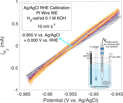
The inset in Fig. 1 illustrates a simple electrochemical setup to calibrate any RE to the RHE scale. In short, in H2-sat'ed electrolyte, a clean flame-annealed (e.g. with a butane torch) Pt wire/mesh WE is cycled by voltammetry vs the RE of interest to find the potential-point at zero measured current for the hydrogen oxidation and evolution reactions (HOR/HER). The RHE calibration can nominally be done in the following steps: (1) Clean Pt and cell, (2) setup 3-electrode cell with the WE (the RHE, namely Pt with H2-saturated electrolyte and active H2 sparging, which in this case is not the RE), the RE to be calibrated, and the CE (carbon or Pt CEs are common; the main CE requirement is that it does not lead to significant contamination of the Pt WE) as shown by the inset in Fig. 1, and (3) optimize cycling of the WE to find the steady state potential–point of zero current.
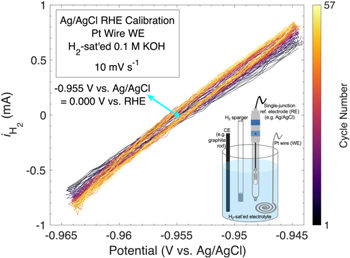
Figure 1. RHE scale calibration of an accumet (epoxy body) sat'ed Ag/AgCl reference electrode (RE) in a batch of 0.1 M KOH showing the measured current under H2-saturation/sparging as a function of potential vs the Ag/AgCl RE under evaluation/calibration. For this particular RE and electrolyte batch, the average potential at zero current, corresponding to 0.000 V vs RHE is ∼–0.955 V vs Ag/AgCl. The electrolyte 16,17 was made from Sigma Aldrich semiconductor grade KOH pellets and 18.2 MΩ cm Millipore water (see RE RHE calibration examples in 0.1 M strong acid in Supplementary Fig. S1). The potential has been 100% corrected for the uncompensated electrolyte resistance (18.1832 Ω) after measurement. The inset at the bottom right illustrates the general electrochemical cell setup to calibrate any RE to the RHE scale. For graphical/visual purposes a single-junction Ag/AgCl RE and a graphite rod counter electrode (CE) are used in the schematic (inset). Although we used a (clean flame-annealed) Pt wire (stored in 30 wt% aqueous nitric acid) as the working electrode (WE), a clean and flame-annealed Pt electrode with large surface area such as a foil or mesh would work just as well. While we employed a graphite rod (grade A) CE, other common CEs are wires, foils, and meshes of metals that are relatively stable at oxygen evolution reaction conditions in the given electrolyte and for which their possible minor corrosion during operation does not have a major impact on the WE performance (contamination due to corrosion of the CE can be mitigated by placing it inside a tube with a porous frit to isolate it from the solution in the main chamber, as shown in Supplementary Fig. S4). 18 Inset not drawn to scale.
Download figure:
Standard image High-resolution imageNotably, it is useful to have a preliminary idea of where the potential-point at zero current would approximately be, i.e. by looking up the tabulated RE's redox couple standard reduction potential scaled for pH via Nernst equation,
12
to avoid large potential range cycling as this could cause some electrochemical Pt dissolution.
12,19,20
If substantial oxidation and dissolution of the Pt WE does occur,
12,19,20
the cell should be vigorously washed and then rinsed with the working electrolyte (overnight aqua regia
21,16
cleaning for glassware can remove major Pt contamination). As shown in Fig. 1 (and Supplementary Fig. S1 (available online at stacks.iop.org/JES/169/066505/mmedia)), once the potential region containing the zero-current point is found (or if it was well guessed/estimated initially), the cyclic voltammetry potential range should be narrowed down to within approximately  0.1 V from this point with a scan rate of
  10 mV s–1. Subsequently, the average potential (vs the RE being calibrated) of zero current from the anodic and cathodic sweeps corresponds to the 0.000 V vs RHE point for the RE of interest in the tested electrolyte batch (Fig. 1). In general, a narrower CV range about the zero current point and a slower scan rate will improve the resolution of the RHE calibration value. The exact number of cycles depends on how long it takes to reach a steady state average potential-point of zero measured current. The slope of the data shown in Fig. 1 initially changes slightly until a steady state is reached; if the slope and/or average zero-current potential-point does not stabilize, this could indicate that the electrolyte is not fully H2-saturated and/or that the Pt wire is contaminated. Once calibrated, before continuing with measurements, the cell (including the RE and CE) ought to be at least vigorously rinsed with working electrolyte three times to mitigate any possible
19,20,22,23
trace Pt contamination (alternatively, one could have a designated, periodically cleaned, cell to perform RHE calibrations; electrodes should always be cleaned).
21,16
The RHE scale is particularly versatile because an RHE can be employed in any electrolyte regardless of pH. Moreover, if the electrolyte pH is known, the RHE can be related to the SHE scale by Nernst equation:
12,13,15
ESHE = ERHE + 0.059 · pH. Accordingly, the RHE calibration measurement of an RE can be used as a pseudo relative pH meter across electrolyte batches. Notably, comparing to the SHE scale can be useful when investigating electrochemical performance as a function of absolute potential (ESHE)-dependent variables such as electrode electric field, which for example owing to its ESHE dependency varies as a function of pH.
24,25
10 mV s–1. Subsequently, the average potential (vs the RE being calibrated) of zero current from the anodic and cathodic sweeps corresponds to the 0.000 V vs RHE point for the RE of interest in the tested electrolyte batch (Fig. 1). In general, a narrower CV range about the zero current point and a slower scan rate will improve the resolution of the RHE calibration value. The exact number of cycles depends on how long it takes to reach a steady state average potential-point of zero measured current. The slope of the data shown in Fig. 1 initially changes slightly until a steady state is reached; if the slope and/or average zero-current potential-point does not stabilize, this could indicate that the electrolyte is not fully H2-saturated and/or that the Pt wire is contaminated. Once calibrated, before continuing with measurements, the cell (including the RE and CE) ought to be at least vigorously rinsed with working electrolyte three times to mitigate any possible
19,20,22,23
trace Pt contamination (alternatively, one could have a designated, periodically cleaned, cell to perform RHE calibrations; electrodes should always be cleaned).
21,16
The RHE scale is particularly versatile because an RHE can be employed in any electrolyte regardless of pH. Moreover, if the electrolyte pH is known, the RHE can be related to the SHE scale by Nernst equation:
12,13,15
ESHE = ERHE + 0.059 · pH. Accordingly, the RHE calibration measurement of an RE can be used as a pseudo relative pH meter across electrolyte batches. Notably, comparing to the SHE scale can be useful when investigating electrochemical performance as a function of absolute potential (ESHE)-dependent variables such as electrode electric field, which for example owing to its ESHE dependency varies as a function of pH.
24,25
The fact that the RHE scale serves as a platform to compare electrode potentials across diverse aqueous electrochemical systems has resulted in its large adoption as the standard reference scale to compare and analyze electrochemical work; it is worth noting that non-aqueous electrochemistry presents different challenges and developing optimal non-aqueous 10,11 REs is an active area of research and discussion. Experimentally calibrating to the RHE scale addresses the problem of accurate, precise, and transparent reporting of potential, but it is also important to consider possible contamination effects of some REs that may impact the performance of electrochemical systems.
Contamination Considerations When Choosing a Reference Electrode
Among the factors influencing RE choice, 13 it is especially important to consider possible contamination of the or from the RE. Electrolyte impurities can poison or modify the electrode material(s), and consequently, the measured electrochemistry. Therefore, it is imperative to consider if the RE can be a source of contamination affecting electrode and/or cell performance. Contamination of the RE refers to when the RE body/parts and/or filling solution get contaminated during an experiment with a contaminant that can affect the performance of an ongoing or separate experiment. Contamination from the RE refers to degradation of the RE body/parts and/or filling solution leakage resulting in contaminants that can affect the electrochemical performance of the WE.
The RE itself could be a source of contamination even if it is clean and free of external impurities.
18,26–30
For instance, it is known that trace contamination of, for instance, Cl–,  Ag, and Hg could measurably affect the apparent electrocatalytic performance of materials.
18,26,27,30,31
As an example of
Ag, and Hg could measurably affect the apparent electrocatalytic performance of materials.
18,26,27,30,31
As an example of  (S-based anions are known to poison Pt-based catalysts)
27,32–36
contamination from a Hg/Hg2SO4 RE, Supplementary Fig. S2 illustrates how ORR performance of a Pt-based electrocatalyst decreases after an Hg/Hg2SO4 RE has substantially contaminated the working electrolyte (in this case after sitting in electrolyte for ∼2 h).
27
Moreover, we have also experienced Hg contamination from a Hg/HgO RE (commonly used in alkaline electrolyte due to its non-glass body), where after seemingly several months of stable and clean performance, the RE unexpectedly started substantially leaking Hg during measurement resulting in Hg plating at the WE (as measured by X-ray photoelectron spectroscopy, see representative measurement in Supplementary Fig. S3) and hindering apparent/measured electrocatalytic performance, ultimately delaying our work. It is important to be aware that the RE filling solution can leak (see manufacturer specifications for rate) and that this could affect electrochemical performance if the system is sensitive to the resulting impurities.
18,30
(S-based anions are known to poison Pt-based catalysts)
27,32–36
contamination from a Hg/Hg2SO4 RE, Supplementary Fig. S2 illustrates how ORR performance of a Pt-based electrocatalyst decreases after an Hg/Hg2SO4 RE has substantially contaminated the working electrolyte (in this case after sitting in electrolyte for ∼2 h).
27
Moreover, we have also experienced Hg contamination from a Hg/HgO RE (commonly used in alkaline electrolyte due to its non-glass body), where after seemingly several months of stable and clean performance, the RE unexpectedly started substantially leaking Hg during measurement resulting in Hg plating at the WE (as measured by X-ray photoelectron spectroscopy, see representative measurement in Supplementary Fig. S3) and hindering apparent/measured electrocatalytic performance, ultimately delaying our work. It is important to be aware that the RE filling solution can leak (see manufacturer specifications for rate) and that this could affect electrochemical performance if the system is sensitive to the resulting impurities.
18,30
In terms of contamination/leaking and general reliability, we have found leakless 37–39 (e.g. from eDAQ or Innovative Instruments) and single (or double) junction (e.g. accumet, glass or epoxy body) 16,17,21,40–43 Ag/AgCl REs to yield acceptable results in most instances (e.g. when trace K+ and Cl– are not of concern; notably these REs can be used with or procured with Na2SO4 filling solution to mitigate Cl– contamination from the more conventional KCl filling solution). Moreover, leaked trace Ag+ has been reported to electroplate onto electrocatalysts under CO2 electroreduction conditions, affecting performance; however, this issue can be mitigated by using an additional electrode/electrolyte junction (as described below, Supplementary Fig. S4). 30 Furthermore alkaline-resistant polymer body Ag/AgCl (or Ag/Ag2SO4) REs can be used in cases where conventional glass-body REs should not be used (i.e. alkaline 26 oxygen evolution reaction (OER) with Fe-, from glass corrosion, sensitive WEs). Ultimately, it is crucial that contaminants arising from the RE are at levels compatible with the electrochemical system of interest.
Chemical contamination from single-junction REs, or by the counter electrode for that matter, can be partly mitigated by using additional electrolyte/electrode junctions as illustrated in Supplementary Fig. S4.
30
Commercial multi-junction Ag/AgCl REs are available. In general, junctions can be added/assembled in house by placing the electrode of interest in a series of isolating tubes with porous frits (see Supplementary Figs. S4, S5 for an example). However, these end up being physically bulkier and thus unsuitable for applications requiring thin REs, and increasing the number of RE junctions could result in increased uncompensated electrolyte resistance (Ru), which could lead to increased noise in measured electrochemical data.
13
While REs can be relatively bulky, low-profile and thin REs are also available. For example, pre-made so-called leakless Ag/AgCl REs with, for example,  2 mm outer diameter, are useful in small cells/reactors.
24,44–50
Issues related to high Ru can be mitigated by placing the RE as close as possible to the WE; if the cell and electrode dimensions allow it, a Luggin capillary
13
RE (Supplementary Fig. S4) can be incorporated to attain a near or practically negligible Ru.
13
2 mm outer diameter, are useful in small cells/reactors.
24,44–50
Issues related to high Ru can be mitigated by placing the RE as close as possible to the WE; if the cell and electrode dimensions allow it, a Luggin capillary
13
RE (Supplementary Fig. S4) can be incorporated to attain a near or practically negligible Ru.
13
Furthermore, commercial REs are often not suitable for applications requiring harsh cleaning protocols (i.e. piranha and/or aqua regia) of glassware and components in contact with electrolyte needed to avoid organic and/or metal contamination, which can be an issue of concern in certain electrochemical systems. 18,36 For example, this is indeed the case for oxygen reduction reaction (ORR) studies of Pt-based electrocatalysts in acidic media, which are sensitive to trace organic, metal, and ionic contamination. 18,36 For such systems, a single-junction modular RHE can be built and used directly as the RE. 18,36
Building a Practical RHE
An in-house built RHE can be an attractive RE for many applications. Such RE would be reliable/stable, modular and made with electrode-casing components chosen according to the chemical resistance required for a particular electrochemical system and/or needed cleaning protocols. Moreover, an RHE can help avoid, for instance, Cl–, Hg,  or other RE-related contamination that maybe be problematic, sometimes arising unexpectedly, with other REs as discussed above (and shown in Supplementary Figs. S2, S3).
18,27,36
Herein, we provide a step-by-step guide on how to build a simple and reliable RHE. A practical general-use (i.e. in 3-electrode heart-shaped-like cells) RHE can be built by placing (1) a clean flame-annealed high surface area solid Pt electrode (e.g. coiled wire or mesh) and (2) a gas dispersion tube (to sparge H2), respectively, into (3) a tube terminated with a porous frit.
36
This practical RHE assembly is sketched in Fig. 2 (pictures of a representative RHE assembly as sketched here are provided in Supplementary Fig. S5). It is important for component (1), the solid Pt electrode, to have a large surface area in contact with clean H2-sat'ed electrolyte to ensure a stable H2/H+ equilibrium. Component (2) is to actively flow/sparge H2 gas and should ideally be placed over the coiled/meshed Pt electrode region, high enough to avoid significant bubble coverage on the Pt electrode that may result in measurement noise or potential instability/drift. Finally, component (3) serves as a single-junction that isolates components (1), (2), and H2 gas from the rest of the electrochemical cell, while letting electrolyte in by hydrostatic pressure. Notably the minimum cell electrolyte fill-level needed to utilize the RHE assembly presented here is that which at least covers the frit of the H2-sparger. When employing a relatively high electrolyte volume in a cell where the RE can be introduced at an angle, enough to substantially fill component (3), the Pt wire could also be placed adjacent to the H2-sparger but slightly above its frit, with the coiled part of the wire in a region away from the H2 bubbles (see schematic in Supplementary Fig. S6).
or other RE-related contamination that maybe be problematic, sometimes arising unexpectedly, with other REs as discussed above (and shown in Supplementary Figs. S2, S3).
18,27,36
Herein, we provide a step-by-step guide on how to build a simple and reliable RHE. A practical general-use (i.e. in 3-electrode heart-shaped-like cells) RHE can be built by placing (1) a clean flame-annealed high surface area solid Pt electrode (e.g. coiled wire or mesh) and (2) a gas dispersion tube (to sparge H2), respectively, into (3) a tube terminated with a porous frit.
36
This practical RHE assembly is sketched in Fig. 2 (pictures of a representative RHE assembly as sketched here are provided in Supplementary Fig. S5). It is important for component (1), the solid Pt electrode, to have a large surface area in contact with clean H2-sat'ed electrolyte to ensure a stable H2/H+ equilibrium. Component (2) is to actively flow/sparge H2 gas and should ideally be placed over the coiled/meshed Pt electrode region, high enough to avoid significant bubble coverage on the Pt electrode that may result in measurement noise or potential instability/drift. Finally, component (3) serves as a single-junction that isolates components (1), (2), and H2 gas from the rest of the electrochemical cell, while letting electrolyte in by hydrostatic pressure. Notably the minimum cell electrolyte fill-level needed to utilize the RHE assembly presented here is that which at least covers the frit of the H2-sparger. When employing a relatively high electrolyte volume in a cell where the RE can be introduced at an angle, enough to substantially fill component (3), the Pt wire could also be placed adjacent to the H2-sparger but slightly above its frit, with the coiled part of the wire in a region away from the H2 bubbles (see schematic in Supplementary Fig. S6).
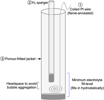
Figure 2. Illustration/schematic of practical single-junction modular RHE assembly. Pictures of a representative RHE assembly as sketched here are provided in Supplementary Fig. S5. This simple assembly can be optimized/customized in many ways to increase robustness such as the assembly shown in Supplementary Fig. S7.
Download figure:
Standard image High-resolution imageBy continuously sparging H2, the electrolyte in component (3) is kept H2-saturated regardless of the gas being sparged in the main electrochemical cell. The practical RHE design presented here, and similar or further optimized adaptations, have been employed successfully before and demonstrated as a reliable and robust RE.
17,27,36,51–53
Many others have also reported directly employing an RHE (example representative reports cited here)
18,54–61
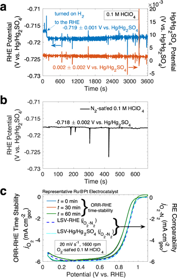
although the exact assembly employed is not always discussed. Figure 3a (left y-axis, blue) shows a  mV potential stability of a representative single-junction RHE over 1 hr (see picture of RHE assembly in Supplementary Fig. S7). As seen in Fig. 3a, the noise in the RHE RE potential time-stability (left y-axis, blue) is comparable to that of a commercial Hg/HgSO4 RE (right y-axis, orange). Moreover, Fig. 3b demonstrates the single-junction RHE potential can be stable within
  mV while bubbling gases such as N2 in the main cell chamber.
27
Oxygen and hydrogen electrocatalysis, while employing an RHE, have also been reported to be stable and reproducible despite O2 and H2 bubbling in the main cell chamber respectively.
27,36,51
While only an indirect measure of RE potential stability, it is notable that the ORR for a representative stable Ru@Pt
27,51
electrocatalyst in Fig. 3c (O2 CVs, left y-axis) shows little performance differences over the course of 1 h despite sparging O2 in the main chamber. Moreover, the performance of the representative characteristic redox profiles (in N2-sat'ed electrolyte, Supplementary Fig. S8) and the ORR activity profiles (O2–N2 LSVs, right y-axis, Fig. 3c) for a representative Pt-based catalyst employing an RHE compared to employing a Hg/HgSO4 RE with fresh (minimally
mV while bubbling gases such as N2 in the main cell chamber.
27
Oxygen and hydrogen electrocatalysis, while employing an RHE, have also been reported to be stable and reproducible despite O2 and H2 bubbling in the main cell chamber respectively.
27,36,51
While only an indirect measure of RE potential stability, it is notable that the ORR for a representative stable Ru@Pt
27,51
electrocatalyst in Fig. 3c (O2 CVs, left y-axis) shows little performance differences over the course of 1 h despite sparging O2 in the main chamber. Moreover, the performance of the representative characteristic redox profiles (in N2-sat'ed electrolyte, Supplementary Fig. S8) and the ORR activity profiles (O2–N2 LSVs, right y-axis, Fig. 3c) for a representative Pt-based catalyst employing an RHE compared to employing a Hg/HgSO4 RE with fresh (minimally  contaninted) electrolyte demonstrate very similar behavior regardless of the RE of choice.
27,51
However, as alluded to above, when using the Hg/HgSO4 RE (sat'ed K2SO4 filling solution),
27
the ORR performance of a representative stable Pt-based catalyst degrades after the RE has sat in the cell for some time (i.e. ∼ 2 h), resulting in stale
contaninted) electrolyte demonstrate very similar behavior regardless of the RE of choice.
27,51
However, as alluded to above, when using the Hg/HgSO4 RE (sat'ed K2SO4 filling solution),
27
the ORR performance of a representative stable Pt-based catalyst degrades after the RE has sat in the cell for some time (i.e. ∼ 2 h), resulting in stale  -contaminated electrolyte that ultimately poisons
32–35
the electrocatalyst (Supplementary Fig. S2).
18
The RHE stability (Fig. 3) regardless of the gas being sparged in the main cell chamber indicates that any trace dissolved gases, with similar order of magnitude or lower solubility (see solubility of common gases in Supplementary Table S1) compared to N2 and O2, that could theoretically diffuse into the electrolyte in the RHE electrode chamber/jacket (component (3)), despite active H2-sparging, do not significantly affect the concentration, and more specifically the chemical activity of hydrogen, resulting in a stable RHE RE potential.
12,13,15,27
Importantly, since RHEs require the use of H2 gas, which at certain concentrations can be flammable, it is important to handle H2 gas carefully,
15
as well as to pre-sparge all electrolyte with an inert gas such as N2 or Ar to remove dissolve O2 from the RHE electrolyte chamber as Pt could thermally catalyze the combustion of H2 and trace O2 in solution.
-contaminated electrolyte that ultimately poisons
32–35
the electrocatalyst (Supplementary Fig. S2).
18
The RHE stability (Fig. 3) regardless of the gas being sparged in the main cell chamber indicates that any trace dissolved gases, with similar order of magnitude or lower solubility (see solubility of common gases in Supplementary Table S1) compared to N2 and O2, that could theoretically diffuse into the electrolyte in the RHE electrode chamber/jacket (component (3)), despite active H2-sparging, do not significantly affect the concentration, and more specifically the chemical activity of hydrogen, resulting in a stable RHE RE potential.
12,13,15,27
Importantly, since RHEs require the use of H2 gas, which at certain concentrations can be flammable, it is important to handle H2 gas carefully,
15
as well as to pre-sparge all electrolyte with an inert gas such as N2 or Ar to remove dissolve O2 from the RHE electrolyte chamber as Pt could thermally catalyze the combustion of H2 and trace O2 in solution.
Figure 3. Representative RHE RE stability. (a) Stability of a practical RHE RE potential (left y-axis, blue) in 0.1 M HClO4 electrolyte 27 (H2 flow/sparging into the RHE assembly was turned on at about t = 200 s) compared to that of a Hg/Hg2SO4 RE (right y-axis, orange); RHE and Hg/Hg2SO4 RHE time-stability reported vs a separate clean Hg/Hg2SO4 RE. (b) Stability of a practical RHE RE potential in N2-sat'ed 0.1 M HClO4 electrolyte (active N2 sparging). (c) Stability of ORR cyclic voltammetry (CV) measurements for a Ru@Pt 27,51 electrocatalyst using a practical RHE RE (left y-axis) and separate characteristic representative ORR linear sweep voltammograms (LSVs; right y-axis) for a Ru@Pt 27,51 electrocatalyst using a practical RHE RE compared to using a Hg/Hg2SO4 RE with fresh/new electrolyte. The LSVs in (c) have been subtracted by their corresponding N2 LSVs (non-ORR current density). Pictures of the exact practical RHE RE assembly used for these measurements is shown in Supplementary Fig. S7. The potential was automatically 85% software-corrected for the uncompensated electrolyte resistance (∼20 Ω) during measurement. 27
Download figure:
Standard image High-resolution image
We have demonstrated the RHE RE assembly potential stability in acid (Fig. 3). While a comprehensive potential stability study of the RHE RE assembly in different kinds of electrolyte (various pH's and ionic species) is needed, it is worth noting that we have found 17,53 reproducible and consistent WE electrochemical ORR performance of, for example, Ag-based electrocatalyst thin films when using the RHE assembly in Fig. 2 in 0.1 M KOH (semiconductor grade pellets) on the timescale of rotating ring disk electrode (RRDE) benchmarking experiments (30–45 min). However, we have previously observed inconsistent behavior/performance in more-glass-corrosive 1 M KOH, which highlights the importance of verifying the reproducibility and consistency of results using any type of RE.
While Pt at 0 V vs RHE is electrochemically stable and therefore Pt contamination of electrolyte owing to dissolution and diffusion into the main chamber is not expected,
22,23
inductively coupled plasma mass spectrometry (ICP-MS) could be employed to quantify trace impurities in electrolyte.
19,20
For a properly-prepared RHE, trace Pt diffusion into the main cell chamber is likely negligible for short-term experiments, and lower than for bare Pt electrodes used directly in the main cell chamber such as commonly used Pt-ring RRDEs and Pt CEs. For instance, with ICP-MS, our measurements indicate near-negligible Pt dissolution and/or electrolyte contamination (within instrument resolution,  ) after ∼30 min of cyclic voltammetry (1–0 V vs RHE) of Ag-based WEs (graphite rod CE) in 0.1 M KOH while employing the RHE assembly in Fig. 2 (Supplementary Fig. S5) as the RE. Moreover, washing the cell and components that contact electrolyte with soapy Millipore water and rinsing three times with the working electrolyte was sufficient to keep any possible Pt contamination at or below trace levels within instrument resolution,
  (10 to 100 ppt). For an in-house built RHE RE assembly (i.e. that in Fig. 2, Supplementary Figs. S5–S7) it is crucial to avoid and mitigate major contamination of the Pt wire/electrode during electrochemical testing as that can lead to RE potential drift. This is an important limitation of RHEs, as this requires that the rest of the electrochemical cell components, specifically the working and counter electrodes, do not corrode, on the timescale of measurement, in a manner that would passivate the Pt wire/electrode. A systematic study of how component corrosion at different pH's affects RHE stability over time would be highly valuable to the field.
The components/parts to build a single-junction RHE (Fig. 2) are available through various commercial vendors such as Pine Research Instruments Inc., ACE Glass, Sigma Aldrich, among many others. Notably, it is much easier to procure glassware that fits standard electrochemical cell ports (i.e. 14/20 port), however, the RHE designs described in this work can be scaled down/up with custom-made glassware or plasticware if the desired part sizes are not readily available commercially. Furthermore, it is reasonable to note that further modifications to the RHE RE system described in this work, such as the addition of a Luggin capillary 13 to decrease the distance between the WE and RE and thus the Ru, would be reasonable and straightforward to implement. Moreover, there are some commercial RHEs available. For instance, gaskatel 62 (among others) distributes RHEs with a different design than presented in this work, including a thin 1.6 mm diameter capillary version without a liquid-liquid junction.
For more fundamental details and technical/engineering intricacies of how to build REs in general we point the reader to the Handbook of Electrochemistry (Ch. 4). 13 Notably, in this work, we provide instructions on how to build a versatile, robust, reusable, modular, and practical RHE that self-fills once introduced into the electrolyte of interest and that is amenable to harsh cleaning protocols. Moreover, we provide schematics and pictures representative of the described RHE assemblies.
Conclusions
Ultimately the choice of RE depends on the researcher's electrochemical system/cell, and factors such as electrolyte uncompensated resistance, cell size, chemical contamination/cleanliness requirements, among others should be considered when choosing an RE. Regardless of RE choice, we emphasize that using the RHE scale generally enables optimal comparability of electrochemical studies and provide streamlined instructions on how to experimentally calibrate any RE to the RHE scale. Moreover, we highlight that an in-house-built RHE RE, in addition to enabling direct measurement vs a standard potential scale, can be a particularly good alternative to commercial REs in cases such as to avoid contamination (i.e. Cl–,  Hg, etc.,) from conventional REs and to have the flexibility to apply harsh cleaning protocols to the RE components. We provide a step-by-step guide on how to build a practical RHE suitable for a broad range of electrochemical systems and show that a well-built RHE can be stable in a range of conditions. We instruct how to accurately measure and report potential vs the RHE regardless of the choice of RE, crucial for proper analysis and understanding of electrochemical processes, ultimately facilitating the advancement of knowledge and technology development for a wide range of emerging applications. We anticipate that this work will benefit a broad range of scientists and engineers with interests in electrochemical studies and applications, particularly given the importance that electrochemistry plays in many emerging technologies, e.g. for energy and sustainability, drawing broader participation in the field.
Acknowledgments
J. A. Z. Z. gratefully acknowledges support of the Gates Millennium Graduate Fellowship/Scholarship. This work was supported by the U.S. Department of Energy, Office of Science, Office of Basic Energy Sciences, Chemical Sciences, Geosciences, and Biosciences Division, Catalysis Science Program to the SUNCAT Center for Interface Science and Catalysis. Some of the RHE RE calibrations were supported by the Toyota Research Institute. A.J. was supported by the Department of Defense (DoD) through the National Defense Science & Engineering Graduate Fellowship (NDSEG) Program. G.A.K. gratefully acknowledges support from the National Science Foundation Graduate Research Fellowship under Grant No. 1650114. We thank Samuel M. Dull, Dr. Adam Nielander, and Prof. Jakob Kibsgaard for valuable discussions.