

Abstract
The failure of the quick rechargeability of SiO-based lithium-ion batteries is examined based on different SOC ranges pre-cycling. In detail, the effect of the SiO electrode during normal C-rate applied cycling on the subsequent quick charge is analyzed. The degradation of the SiO electrode is greatly influenced by the design of cycling SOC range of the SiO/NCM811 cell, and severe mechanical and solid electrolyte interphase degradation of the SiO electrode occurred with highly utilized SiO electrodes, resulting in Li plating on the SiO surface under quick charge conditions due to the low open-circuit voltage of SiO electrode and high charge transfer resistance, which is derived from the Li-trap at SiO and subsequent SEI development and electrode crack. The degraded SiO electrode is vulnerable to Li plating at high C-rate applications; hence, the pre-cycling condition of the SiO electrode influences the quick rechargeability of the SiO/NCM811 cell. Consequently, proper manipulation of the cycling range of SiO-based cells should be conducted to enhance the durability of SiO-based quick rechargeable cells.
Export citation and abstract BibTeX RIS
While the lithium-ion batteries (LIB) are widely applied as the electrification of the automobiles, 1–3 the facile re-fueling of loaded battery system should be improved for the further replacement of internal combustion engines. 4,5 A previous report has suggested that the quick chargeability of battery systems for electric vehicles should exceed 5.0 C, 6,7 hence, a drastic improvement in the Li storage kinetics of battery systems should be realized. 8–10 The most crucial design strategy for improving the quick-charge performance of LIBs is to switch the negative electrode 11–14 from the conventional graphitic carbon to a Si-based system because Si active material stores Li-ions with a specific energy that is approximately ten times higher than that of a graphite electrode, 15–17 thus, a thin negative electrode application is possible at identical specific energy cell designs, 18 which is desirable for Li diffusion into the electrode at high C-rate applications. 19,20 Moreover, the lithiation potential of Si-based negative electrodes is higher than that of graphite electrodes. 21,22 Therefore, the possible Li-plating on graphite surfaces at high C-rate applications can be mitigated by Si-based negative electrode applications. However, Si-based negative electrodes suffer mechanical degradation 23,24 of the electrode structure and the formation of an SEI film on the Si surface, 25,26 which leads to Li trapping at the Si-based active material. 27,28
This study is motivated by the fact that the specified degradation mechanism of Si-based negative electrodes can affect the quick charge performance of Si-comprised cells after normal cycling. The lithiation/de-lithiation degrees of Si-based negative electrodes during low C-rate cycles have a significant impact on the deterioration of Si-based negative electrodes, 26,29 and this cycle history can impair the rapid chargeability of Si-based battery systems at low C-rate cycles. The influence of the degree of degradation of Si-based negative electrodes on quick charge performance, on the other hand, has not been well studied. Two distinct designs for discharge-end state-of-charges (SOCs) were chosen to manage the volumetric expansion of Si-based electrodes to examine the influence of pre-cycling history on the quick chargeability of Si-based full cells. After several cycles at low C-rates with the two SOCs, a 6-min quick charge protocol was applied to evaluate the cycle performance. 22 The degradation mechanism of quick charge cycling for differently degraded SiO-based negative electrodes comprising full cells is discussed, and a mitigation strategy is suggested.
Experimental
Electrode preparation
The positive electrode was prepared by applying lithium nickel manganese cobalt oxide (LiNi0.8Co0.1Mn0.1O2, NCM811, EcoPro BM) as the active material, carbon black (Super P, Timcal) as the conductive agent, and poly(vinylidenefluoride) as the binder (KF-1100, Kureha) with a 95:2.5:2.5 wt.% ratio. The mixed powder was dispersed in N-methyl-2-pyrrolidone (NMP, Sigma Aldrich), and the slurry was coated on 15 μm thick Al foil. The coated electrode was pre-dried at 80 °C for 5 h and placed in a vacuum for 12 h at 120 °C. The negative electrode was prepared using a mixture of SiO (DMSO, Daejoo Electronic Materials) and flake graphite (SFG6, Timcal) with poly(acrylic acid)/poly(vinyl alcohol) (PAA, Sigma-Aldrich, Mw = 250,000/PVA, Sigma Aldrich, Mw = 19,000–23,000, 9:1 ratio) binder in DI water with a 7:2:1 wt.% ratio. The slurry was coated on 20 μm thick Cu foil and dried at 80 °C for 12 h under vacuum. After vacuum drying, the negative electrode was heated in a vacuum oven at 150 °C for 1 h to cross-link the PVA and PAA binders. 30
Evaluation of laminated pouch cell
A pouch-type cell was assembled by stacking the positive electrode/polyethylene (PE, NH616, Asahi Kasei) separator/negative electrode. The designed negative-to-positive electrode capacity ratio (NP ratio) of the cell was 1.04 based on a charge (de-lithiation) areal capacity of approximately 2.08 mA h cm−2 for the negative electrode. After injecting 1.0 M LiPF6 in EC/EMC (3:7 = v/v) electrolyte (Dongwha electrolyte), the cell was thermally sealed and aged for 24 h at room temperature. The cell was conducted with a 0.1 C CC charge for 3 h, and the pre-charged cell was stored at room- and high-temperature for 1 d to stabilize the surface film deposited on the electrode. After the stabilization period, galvanostatic charge-discharge pre-cycling (TOYO, Japan) was performed with 0.33 C CC-CV charge (0.05 C current cut-off) and 0.33 C discharge. After pre-cycling, the normal C-rate cycling was conducted with 0.5 C CC-CV charge (0.05 C current cut-off) and 0.5 C discharge with an SOC range of 0–100 (4.2–2.5 V) or 20–100 (4.2–3.15 V). During the cycle, the open-circuit voltages (OCV) at the discharge end were recorded after 10 min of the discharge-end rest period. Protocol-based quick charge cycling was designed to charge 60% of the designed cell capacity within 6 min. 22
Post-mortem electrode analysis
To investigate the chemical composition, electrode structure and the OCV values of the negative electrode after quick and normal charge cycles, X-ray photoelectron spectroscopy (XPS, Scientific K-ALPHA, Thermo Fisher) and scanning electron microscopy (SEM, JEOL JSM-IT200) analyses were conducted in a dry room. The cycled electrodes were dismantled in an Ar-filled glove box, and the electrodes were washed with ethyl methyl carbonate (EMC, Dongwha electrolyte) to remove residual salt and solvent and dried under vacuum for 12 h.
Electrochemical impedance spectroscopy
A negative electrode symmetric cell was fabricated to measure the resistance of the SiO electrode after quick charge cycling. To stabilize the OCVs of the cycled SiO electrode, a CC-CV discharge step of 2.5 V was applied to fully de-lithiate the SiO electrode. The SiO/Li/Li three electrode cell was assembled with beaker-type cells, and fresh 1.0 M LiPF6 in EC/EMC (3:7 = v/v) was injected. Potentiodynamic electrochemical impedance spectroscopy (EIS) measurements were conducted in a frequency range of 10.0 mHz to 3.0 MHz at 5.0 mV.
Results and Discussion
Two distinct SOC ranges were selected to differentiate the degree of degradation of the SiO electrode. A previous study demonstrated that the discharge voltage of SiO-based negative electrodes greatly influences the mechanical degradation of SiO electrodes in the Li/SiO cell, 31 hence, the depth of discharge (DOD) of the cell was controlled. (Fig. 1a) Whereas the SOC 0–100 cycle with a cell voltage range of 2.5 to 4.2 V demonstrates a sharp decrease in the discharge voltage because of drastic de-lithiation of the SiO electrode, the SOC 20–100 cycle demonstrates a gradual decrease and increase in the cell voltage during discharge and charge, which is a result of the limited manipulation of the negative electrode capacity.

Figure 1. (a) Cell voltage vs. accumulated capacity profile and (b) cycle performance with 0.5 C for SiO/NCM811 cell with two different SOC swing ranges, (c) the quick charge-protocol for 6-min charging, and (d) SOC 20–80 range 6-min quick charge cycle performance obtained from three differently pre-cycled SiO/NCM811 cells.
Download figure:
Standard image High-resolution imageFigure 1b shows the 0.5 C CC-CV charge and 0.5 C discharge cycle results obtained from the SiO/NCM811 cell with two different SOC ranges. The cycleability of the identically designed cell with narrow and wide SOC swing ranges was very different. The capacity retention from the SOC 0–100 range is approximately 76%, while the retention from the SOC 20–100 range is 87%; hence, the degradation degree of the SiO electrode is predicted to be severe with an SOC 0–100 swing range. These two differently degraded SiO/NCM811 cells were exposed to the 6-min quick charge condition, as shown in Fig. 1c. The stepwise 20.0 C to 2.5 C currents was applied to low SOC to high SOC with a set charging time to satisfy the 6-min charge in the range of SOC 20–80, and the discharge current was 0.5 C CC. The resulting quick charge performances from the intact, 100th 0.5 C SOC 20–100, and SOC 0–100 cycled SiO/NCM811 cells are shown in Fig. 1d. The charged capacity from the high C-rate application decreases with SiO/NCM cell degradation, and so the order of discharge capacity is intact, SOC 20–100 cycled, and SOC 0–100 cycled cells. While gradual capacity fading was observed in the intact cell following quick charge protocol application, pre-cycling accelerated the deterioration of SiO/NCM811 cells even though the SiO negative electrode was less utilized. Moreover, the acute degradation of the SiO/NCM811 cell after a quick charge cycle was demonstrated for SOC 0–100 cycling. The severe failure of discharge capacity retention after the 80th cycle was observed for the 100th SOC 0–100 cycled SiO/NCM811 cell, whereas the intact cell and SOC 20–100 cycled cell exhibited enhanced cycleability.
To verify the origin of the extreme capacity decay during the quick charge cycle after the 100th SOC 0–100 0.5 C cycle of the SiO/NCM811 cell, post-mortem electrode surface morphology and chemical composition analysis were conducted using SEM and XPS on samples processed under dry room conditions (Fig. 2). The quick-charged intact cell demonstrates a clean negative electrode morphology, and the Li 1 s XPS spectrum indicates that the typical SEI components (LiF and Li2CO3 32,33 ) are grown on the SiO active material surface (Fig. 2a). Whereas intact cells demonstrate clean surface morphology and SEI-based chemical components, the quick charge cycled electrode after 0.5 C pre-cycling demonstrates mossy and dendritic deposits on the SiO surface. Moreover, the growth of Li dendrites (white arrow) on the SiO electrode after quick charge cycling was higher for the SOC 0–100 range cycled electrode (Fig. 2c) than it was for the SOC 20–100 cycled electrode (Fig. 2b). The development of the SEI film on the SiO electrode is also directly correlated with the amount of Li deposition 34 on the SiO surface during high current application; hence, the LiF, Li2CO3, and Li2O 35,36 components increased for the highly utilized SiO electrode during pre-cycling. Consequently, the acute degradation of the SOC 0–100 pre-cycled SiO/NCM811 cell during the quick charge application resulted from the Li dendrite growth on the SiO electrode surface. Because the Li dendrite growth on the SiO electrode surface is highly relevant to the capacity retention after normal C-rate cycling of the SiO/NCM811 cell, the state of the SiO electrodes was further investigated based on thermodynamic and kinetic aspects.
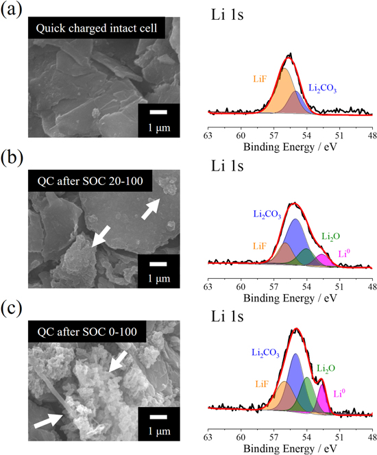
Figure 2. ex-situ SEM and Li 1 s XPS spectra obtained from 200th quick charged SiO electrode with (a) intact cell, 200th quick charged after 0.5 C 100th cycled at (b) SOC 20–100 and (c) SOC 0–100 ranges.
Download figure:
Standard image High-resolution imageBecause Li metal deposition during quick charge application on the SiO electrode can occur when the electrode is exposed to voltages less than 0.0 V (vs Li/Li+), the possibility of Li deposition during high C-rate application increases with a shift of the negative electrode voltage to the low-potential region; hence, the OCVs of negative electrodes after normal cycling were recorded and analyzed using the galvanostatic intermittent titration technique (GITT) (Fig. 3). While the discharge-end OCVs of the SiO/NCM811 cell gradually increased with SOC 20–100 cycling (below 0.1 V after 100th cycle), the severe growth of the discharge-end OCV was observed from the SOC 0–100 cells, i.e., approximately 0.5 V after the 100th cycle (Fig. 3a). Because the increase in discharge-end OCVs during the cycle at the SiO/NCM811 cell indicates the irreversibility of the cell, the number of trapped Li ions in the degraded SiO electrode is predicted to be higher for the SOC 0–100 cycled cell than it is for the SOC 20–100 cycled cell. The voltage mapping of the SiO negative electrode after the 100th SOC 20–100 and SOC 0–100 cycle is performed to visualize the Li-trapping degree after cycling. (Fig. 3b) The OCV values are recorded after fully discharge of the SiO/NCM811 cell after 2.5 V CC-CV discharge step. The contour plot shows that the SOC 20–100 cycled electrode is highly de-lithiated, as seen by negative electrode voltages higher than 0.6 V (vs. Li/Li+). The voltage distribution of the SOC 0–100 cycled negative electrode, on the other hand, is less than 0.5 V (vs. Li/Li+), indicating a higher degree of Li-trap at the SOC 0–100 cycled SiO/NCM811 cell. To evaluate the degree of trapped Li ions at the SiO electrode after the 0.5 C 100th cycle with two differently designed SOC range cycles, the GITT test was performed. Because the GITT plot can be used as an indicator of the Li-ion trapping degree using the recorded voltage, 27,37 a Li/SiO cell was also assembled to measure the OCVs with a dismantled electrode from the various cycling conditions after discharge of the SiO/NCM811 cells. The OCV of the SiO electrode obtained after the formation of the SiO/NCM811 cell was 1.08 V (vs. Li/Li+); thus, the amount of Li ions trapped at the SiO electrode is negligible at the initial state. However, the OCV values from the SOC 0–100 and SOC 20–100 cycled SiO electrode were 0.71 V and 0.36 V (vs. Li/Li+), respectively. The obtained OCV values indicate that more than triple the amount of Li ions was trapped at the SOC 0–100 cycled SiO electrode compared with the SOC 20–100 cycled SiO electrode (Fig. 3b), which leads to decreased negative electrode voltages after cycling. Therefore, the trapped Li ions increase the possibility of Li deposition at high C-rate applications as a result of the shift of the voltage of the SiO electrode toward the low-voltage region by Li trapping at the SiO electrode.
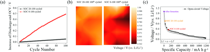
Figure 3. (a) Cycle number vs. increase in discharge-end OCV during 0.5 C cycle of SiO/NCM811 cell with two different SOC ranges (b) contour plot of OCV values of SiO negative electrode after 100th cycle at two different SOC ranges and (c) GITT plots recorded from 0.1 C CC 10-min and 20-min rest periods applied to Li/SiO cell. Inset: OCV values obtained from the Li/SiO cell. The electrodes were collected after formation and for the 0.5 C 100th cycled SOC 20–100 and SOC 0–100 SiO/NCM811 cells.
Download figure:
Standard image High-resolution imageAs the Li-ion trap into the SiO electrode is known to originate from the pulverization of the SiO electrode 38,39 and the formation of electrically disconnected particles, 40,41 the resistance of the SiO electrode increases with the trapping degree of Li ions. To compare the electrode resistance failure of the SiO electrode, the Li/Li/SiO three electrode cells after the 100th cycle with SOC 0 and SOC 20 to 100 range were evaluated (Fig. 4a). Before dismantling the cell, the CC-CV discharge step was applied to the SiO/NCM811 cell to unify the electrochemical state of the SiO electrode. The Nyquist plots of the Li/Li/SiO three electrode cell indicate that the resistance of the SiO electrode from the SOC 0–100 cycled cell is higher than that of the SOC 20–100 cycled cell. Moreover, the resistance value obtained from the frequency range of the charge transfer reaction (c.a. 300 Hz) 42 of the SiO electrode is higher in the SOC 0–100 cycled cell; hence, the voltage of the SOC 0–100 cycled SiO electrode during the quick charge step can be readily decreased to below than 0.0 V (vs. Li/Li+). The analyzed resistance values from the cycled two electrodes are also compared (Fig. 4b). For the 100th SOC 20–100 and SOC, the RSEI values are 151 and 228 Ω mg, respectively, and the RCT values are 322 and 847 Ω mg, indicating a degradation in interlocking resistance with a wide range SOC cycled electrode. While wide-ranged SOC cycling does not significantly increase interphase resistance, SOC 0–100 cycling massively increases charge transfer resistance of the SiO electrode. Because the failure in charge transfer resistance is critically impacted by the network failure of the electrode, 43 a structural analysis of the cycled electrode was performed.

Figure 4. (a); Nyquist plots recorded from Li/Li/SiO three electrode cell and (b) fitted RSEI and RCT values with SiO electrode from SOC 0–100 and SOC 20–100 100th cycled SiO/NCM811 cell.
Download figure:
Standard image High-resolution imageTo investigate the electrode and interphase degradation of the SiO electrode, ex situ SEM and XPS analyses were conducted. The SEM images of the degraded SiO electrode (Fig. 5a) show that a severe crack of the electrode developed at the top of the electrode, as seen in the cross-sectional view of the SOC 0–100, 100th cycled SiO electrode, whereas the SOC 20–100 cycled electrode maintained its initial electrode structure after the 100th cycle. The C 1 s XPS spectrum (Fig. 5b) indicates that intense signals of C-O/O-C = O, 44,45 and Li2CO3 33,46 are observed from the SOC 0–100 cycled SiO electrode, which is evidence of the severe thickness of the SEI film deposited on the SiO surface. Meanwhile, the SOC 20–100 cycled SiO electrode demonstrates suppressed Li trapping in the SiO electrode because of the low volumetric change of the SiO electrode occurring as a result of the limited utilization of SiO; hence, the growth of the SEI component on the SiO electrode surface subsequently decreased. Consequently, the SOC 0–100 cycled SiO electrode is vulnerable to Li deposition during a quick charge cycle because the electrode potential is located in the low-voltage region from the high degree of Li-trapping in the SiO electrode, and the increased resistance of the electrode results from the pulverization of the SiO electrode and the thick SEI film deposited on the SiO surface. In short, the degradation mode of the SiO electrode can affect the failure of the quick charge cycle.
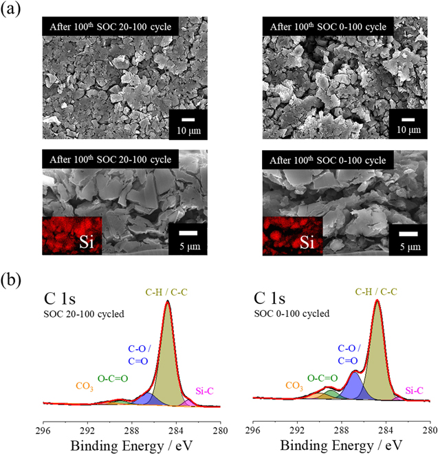
Figure 5. post-mortem (a) SEM image and (b) top-most C 1 s XPS spectrum of cycled SiO electrode obtained from 100th cycled SOC 0–100 and SOC 20–100 100th cycled SiO/NCM811 cells, respectively.
Download figure:
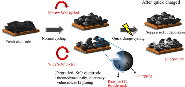
Standard image High-resolution imageThe summarized effect of the pre-cycle history of the SiO electrode during quick charge application is shown in Fig. 6. The degree of utilization of the SiO electrode greatly influences the SiO electrode voltage and the resistance of the electrode after normal cycling. The low voltage shift of the SiO electrode and higher resistance of the negative electrode at normal cycling have a significant impact on the formation of Li dendrites during subsequent quick charge protocol application, resulting in hastened cell deterioration. The degradation of the SiO electrode is minimized at low SiO-utilizing cycle condition, resulting in better quick charge performance. The failure of SEI film deposited on the SiO electrode and the degradation of electrode structure are inhibited at narrow SOC normal cycling, suppressing Li deposition on the SiO electrode at followed high C-rate applications. As a result, the failure of SiO/NCM cell failure during quick charge cycling is limited. Meanwhile, the high current application after a high degree of SiO utilization shows significant deterioration of capacity retention during the quick charge cycle, which is caused by increased electrode resistance and decreased SiO electrode voltage. The accelerated degradation from the severely developed Li dendrites during quick charge cycling resulted in the kinetically and thermodynamically vulnerable negative electrode state that is obtained from the high SOC range normal cycle history. Accordingly, proper control of the SiO electrode is crucial for maintaining the initial performance of quick-rechargeable LIBs because the damage to the SiO electrode during normal cycling significantly influences the cycle performance at high current applications.
Figure 6. Schematic diagram of accelerated failure of SiO electrode during quick charge condition according to the pre-cycle history.
Download figure:
Standard image High-resolution image
Conclusions
The failure of SiO-based LIBs designed for quick rechargeable batteries was investigated based on different SOC ranges pre-cycling. Specifically, the effect of the degradation of the SiO electrode during normal C-rate applied cycling on the subsequent quick charge was analyzed. The major mechanisms are summarized as follows.
- (i)The degradation of the SiO electrode is greatly influenced by the design of the cycling SOC range of the SiO/NCM811 cell, and the degradation of the discharge capacity retention of the SiO/NCM811 cell is directly correlated with the degree of utilization of the SiO electrode.
- (ii)The mechanical and interphase degradation of the SiO electrode changes the OCV and the resistance of the electrode after cycling. The voltage of the SiO electrode shifts negatively after high utilization of the SiO electrode because of the Li-trap and the pulverization of SiO, and the electrically disconnected SiO particle generation in the negative electrode after cycling increases the resistance of the electrode, which leads to Li plating on the SiO surface under quick charge conditions.
- (iii)The high utilization of the SiO electrode diminishes the quick rechargeability of the SiO/NCM811 full cell; hence, the utilization degree of the SiO-based cell should be well controlled to enhance the durability of the cell.
Acknowledgments
This work was supported by the Ministry of Trade, Industry & Energy/Korea Evaluation Institute of Industrial Technology (MOTIE/KEIT) (No. 20011905, 20014638, 20016056).