

Abstract
Lithium-ion-based all solid-state batteries (ASSBs) with inorganic solid-state electrolytes have attracted much attention due to their high energy density, excellent mechanical-electrochemical stability, and lower manufacturing cost. Also, from an environmental perspective ASSBs guarantee a cleaner alternative to fossil-fuel-based applications. Relatively lower Li-ion conductivity of most inorganic solid-state electrolytes and higher electrode-electrolyte interfacial resistance are the most challenging aspects of inorganic solid-state electrolytes. Here, to support researcher's understanding of the inorganic solid-state electrolytes, we have summarized the background and recent advancements in the fundamental understanding of the heart of ASSBs i.e. the inorganic solid electrolytes, by addressing the domains of their structure, Li-ion transport mechanism and the current processing routes. Also, strategies to enhance the performance and stability of ASSBs, the optimization of electrode-electrolyte interfacial resistance are discussed.
Export citation and abstract BibTeX RIS
With the help of the Sony and Asahi Kasei group, Yoshio Nishi introduced the first Lithium-ion battery in 1990. 1 Since commercialization, Li-ion batteries have achieved great marketplace due to their advantages such as 1- high energy density 2- high operating voltage & 3- long life cycle. Nowadays Li-ion batteries are being used in portable electronics (such as mobile & laptops), electric vehicles, hybrid electric vehicles & standing energy storage systems, etc. 2,3
However, the use of thermally unstable & flammable organic electrolytes makes conventional Li-ion batteries less safe i.e. fire accidents and explosions are reported due to the formation of dendrites of Lithium. Also, low power density, insufficient lifetime, electrolyte leakage, and higher cost are the other drawbacks of conventional Lithium-ion batteries. On the other hand, Lithium-ion batteries with non-flammable solid-state inorganic electrolytes have following advantages over conventional Li-ion batteries-
- ASSBs show high energy and power density.
- ASSBs are highly safe due to the mechanical preventing of solid-state electrolytes from leaking and burning.
- ASSBs have better electrochemical stability and show wider electrochemical window (>6 V vs Li/Li+).
- Solid-state electrolytes have excellent mechanical strength thereby ensuring the long-term durability of ASSBs.
- ASSBs have fewer requirements of packaging and state-of-charge monitoring circuits and therefore are easier to design.
- In ASSBs the solid-state electrolytes work as separators at the same time it also works as electrolytes.
- Lesser side reactions are reported in ASSBs between solid electrolyte and electrodes. 2–6
Considering the above advantages, ASSBs has become one of the very fast-growing research domains in energy storage applications. However, the development of ASSBs is limited by two major factors. The first one is low ionic conductivity and the second one is high interfacial resistance between active electrodes and solid-state electrolytes. It is expected that ASSBs might be used widely in electric and hybrid electric vehicles, as well as in electronic devices due to their high energy/power density and safety. Therefore, recent advancement and intensive research are underway on inorganic materials which will be suitable for the development of solid-state electrolytes in ASSBs. 5,7
The working principles of conventional Li-ion batteries and ASSBs are similar (Fig. 1). During discharging, Li-ions de-intercalate from anode to the cathode via electrolyte and electrolyte-electrode interfaces. Meanwhile, as shown in Fig. 1, the electrons follow the external path to reach to cathode from the anode. Whereas in charging, the Lithium ions and electrons flow reversely.

Figure 1. Schematic diagram for Charging & Discharging of ASSBs. The electrode-electrolyte interface layer created due to reaction between electrode-electrolyte materials is shown in red. The intercalated lithium ions within electrodes are shown as blue spheres.
Download figure:
Standard image High-resolution imageIn conventional Li-ion batteries, separators are intentionally introduced in electrolytes to hinder direct transportation of electrons from anode to cathode and vice versa. It prevents short circuits in the battery. However, in ASSBs the solid-state electrolyte itself works as a separator. An ideal solid-state electrolyte should have the following properties-
- The performance of ASSBs depends on the movement of Li-ions within the electrolyte; thus at room temperature, the solid-state electrolytes are supposed to have the minimum ionic conductivity of 10−4 S cm−1 and about zero electronic conductivity.
- Solid-state electrolytes should exhibit a higher electrochemical stability. 2
- The solid-state electrolytes should have good mechanical properties.
- For smooth ionic conduction, the solid-state electrolytes used in ASSBs should have a sufficient quantity of mobile Li-ions. Therefore, to allow the ions to move, the solid electrolytes should have sufficient vacancies in their crystal lattice facilitating the hopping of ions.
- The overall activation energy of solid-state electrolyte must be low. 8
As shown in Fig. 2, ASSBs utilizes mainly three types of solid-state electrolytes namely; solid polymer electrolytes [SPEs], organic-inorganic hybrid composite electrolytes and inorganic solid-state electrolytes [ISEs]. Among all, oxides and sulfide-based solid-state electrolytes are the two categories of ISEs. Solid oxide electrolytes are resistant to ambient air, water and high temperature and therefore, are considered as the most promising solid-state electrolytes whereas sulfide-based solid electrolytes show the highest ionic conductivity challenging to that of organic electrolytes. 3,9 Despite the highest ionic conductivity, these are far away from the practical application as sulfides easily react with ambient air and water.

Figure 2. Shows a schematic representation of All Solid State Li ion Batteris (ASSBs). The Solid state electrolytes (SSE) are the important factor of ASSBs. As depicted, SSEs used in ASSBs have been classified in three groups. On the basis of excess material used in the synthesis of Inorganic solid state electrolyte, it has been classified in two group i.e. Oxides and Sulfides. As shown in figure, they are classified on the basis of their structures, ionic conductivities, synthesis methods and compounds/elements used in preparation of respective SSEs.
Download figure:
Standard image High-resolution imageHere, in this article, we will be focusing on the recent advancement and progress of oxide and sulfide-based solid-state electrolytes. Moreover, the key challenges and future possibilities for the development of inorganic solid-state electrolytes will also be discussed in detail.
Inorganic Solid-State Electrolytes (ISEs)
The inorganic solid-state electrolytes can be categorized into two groups: oxide and sulfide solid-state electrolytes. The oxide solid-state electrolytes have good thermal and electrochemical stability but low ionic conductivity and low mechanical strength, which hinder their application in an energy storage system.
Lithium Sulfide (Li2S) and the sulfides of Silicon (SiS2), Phosphorous (P2S5), and Germanium (GeS2), etc are in the primary composition of sulfide type solid-state electrolytes. Lesser electronegativity and larger size of S2− in sulfide solid-state electrolytes tend to bound S2− loosely with lithium ions. It makes the transportation of lithium-ion facile inside the electrolyte and therefore these show higher lithium-ion conductivity than oxide solid-state electrolytes at room temperature. 6
Oxide solid-state electrolyte:
NASICON type solid-state electrolyte
The three-dimensional framework structure of NASICON [NAtrium Super Ionic CONductor] was proposed by Hong and Goodenough et al. 10,11 High ionic conductivity and excellent structural stability are the key fascinating properties of NASICONs. Na1+x Zr2P3−x Six O12 [0 ≤ x ≤ 3] was the first NASICON type solid-state electrolyte. The 3D framework of AMM'P3O12 or AMM'[PO4]3 NASICON structure is shown in Fig. 3, where "A" is Li and Na, M is Ti, Ge, Sn, Hf, or Zr & M' is Cr, Al, Ga, Sc, Y, In, or La. In the framework of NASICON, the phosphorus can be partially replaced from S, Si, or As. 12–14 The 3D NASICON structure is made by the robust connection of MO6 octahedra and [S, Si, As, P]O4 tetrahedra by sharing the corner oxygen. Over every two octahedral, three tetrahedral are present in this 3D framework structure 15 Fig. 3 shows the Li-ion occupies two different sites: in 6-fold coordination octahedrally symmetric site M, and/or 8-fold coordinated site M', located between two columns of M'O6 octahedra. The lithium-ion migrates via hopping between these two M and M' interstitial positions through the bottlenecks. The size of the bottleneck depends on the type of skeleton ions and carrier density at both interstitial positions. Consequently, the structure and ionic conduction of NASICON compounds depend on the lattice parameters of the cell, whose values can be varied by selecting chemicals of different compositions. It has been seen that the materials with long lattice parameters show higher ionic conductivity. Also, the cell of the long lattice parameter increases the size of the bottleneck thereby increasing the lithium-ion conduction. 14,16–18 Choosing M' as Al3+ and Cr3+ in AMM'[PO4]3 induces more lithium ions at vacant M' sites. At the same time, it also increases the unit cell parameter and therefore bottleneck size, which further increases the ionic conductivity in NASICON type solid-state electrolytes. 19 Though, due to the formation of the secondary phase of Al3+ or Sc3+ and large ionic radius mismatch, the substitution level can't be taken beyond 15% (i.e. x = 0.3). To date, Li1.3Al0.3Ti1.7 [PO4]3 is the best-reported NASICON lithium-ion conductor with bulk conductivity [σ ≈ 3 × 10⁻³ S cm−1] at room temperature. 20
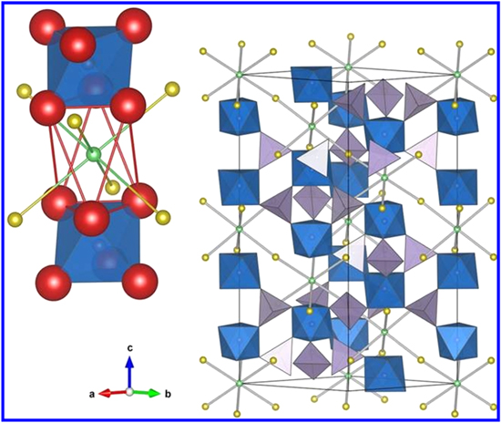
Figure 3. Representation of a regular NASICON structure. The lithium ion transportation occurs between sites M and M' shown in green and yellow spheres respectively. The uplifted image in left shows the close view of lithium ion pathway from the Oxygen bottleneck window. 16
Download figure:
Standard image High-resolution imageLISICON type solid-state electrolyte
The term LISICON stands for Lithium-Super-Ionic-Conductor. Hong and his co-workers started the study on the Li2+2xZn1−xGeO4 family and at 300 °C they reported an ionic conductivity of 1.25 × 10⁻¹ S for Li14Zn [GeO4]4. 2,21,22 Similar to γ-Li3PO4, the crystal structure of LISICON is made of a rigid three dimensional [Li11Zn [GeO4]4]3− network and three loosely bonded Lithium ions having an orthorhombic unit cell of lattice parameters a = 10.828Å, b = 6.251 Å, c = 5.140 Å, and z = l, and Pnma space group with tetrahedrally co-ordinated cations. 14,22 Similar to other NASICON like super-ionic conductors, LISICON also contains a high density of mobile lithium ions occupying the sites in the interstitial space of the 3D network. In this network, two factors govern the conduction of Li-ion − 1] the bottleneck size between adjacent sites i.e. 4.38 Å, which is more than enough for the smooth transportation of Li-ion between interstitial sites, and 2] the natural bonding between free Li-ion and anion [O−] network. The network anion has strong covalent bonding with all the three cations [Li+, Zn2+, Ge4+], particularly with Li+, which leads to the polarization of oxygen charge density away from interstitial ions and thus weakening the bonding with mobile Li-ion. The weak bonding between cations and oxygen anions further supports the fast movement of Lithium-ion. It is important here to note that due to the parallelogram shape of the bottlenecks, the lithium ions in Li14Zn [GeO4]4 can diffuse only in two dimensions. 22 It has been observed that due to lower migration energy [0.21 eV–0.35 eV], the interstitial diffusion of Li-ions in LISICON microstructure is dominant over vacancy diffusion with migration energy of 0.56 eV. 23 Even at such lower migration energy, the doped LISICON compounds, such as γ-Li14.4 V1.6Ge2.4O16, show relatively poor ionic conductivity [10−6 S cm−1] as compared to that of liquid electrolytes [10−2 S cm−1] at room temperature. Also, LISICONs react with lithium metal and atmospheric gases [such as CO2], which degrades their performance. Lower ionic conductivity and reactivity with ambient atmosphere hinder the use of LISICONs in ASSBs and other devices. 17
Therefore, to increase the ionic conductivity of LISICONs, Noriaki Kamaya et al. 24 replaced oxygen with sulfur to develop this LISICON, Li10GeP2S12, having ionic conductivity in the of order 10−2 S cm−1 at room temperature. This family is to be discussed in detail in the upcoming sulfide section.
Perovskite type solid-state electrolyte
In solid-state inorganic chemistry, Perovskite structure [ABO3] with space group Pm
 m [space group number 221], is encountered almost everywhere. This structure was reported by Latie et al.
25
for the first time. It holds most of the metallic ions of the periodic table with a considerable number of different anions. The cubic unit cell of perovskite is shown in Fig. 4,
26
where A-site ions [usually alkaline-earth or rare-earth elements] sits at the center of the cell, transition metal ions B sits at the corners, whereas the oxygen atoms sits at the face-centered positions of the corer shared octahedra. Here it is important to note that A sites are in 12-fold coordination and B sites are in 6-fold coordination oxygen anios.
27
m [space group number 221], is encountered almost everywhere. This structure was reported by Latie et al.
25
for the first time. It holds most of the metallic ions of the periodic table with a considerable number of different anions. The cubic unit cell of perovskite is shown in Fig. 4,
26
where A-site ions [usually alkaline-earth or rare-earth elements] sits at the center of the cell, transition metal ions B sits at the corners, whereas the oxygen atoms sits at the face-centered positions of the corer shared octahedra. Here it is important to note that A sites are in 12-fold coordination and B sites are in 6-fold coordination oxygen anios.
27

Figure 4. Schematic representation of a typical Perovskite structure. 26
Download figure:
Standard image High-resolution imageThe lithium-ion conductivity in perovskite structured Li3xLa2/3−xTiO2 [LLTO] compounds was studied by Inaguma et al. 28–30 Oguni et al. 31 and Kawai et al. 32 These authors have shown that in perovskites structures, the cation deficiency present at sites-A favors fast ionic conduction through the bottlenecks formed by four nearby octahedra, BO6. The A and B sites of perovskites can hold different ions of different valence states. To optimize the best ionic conductivity, several substitutions have been done for sites A and B, 33 but Inaguma et al. 28 achieved the best results for Li3xLa2/3−xTiO2 compounds. At room temperature for Li0.34[1]La0.51[1]TiO2.94[2], they have obtained bulk ionic conductivity of 1 × 10⁻³ S cm−1 and total ionic conductivity greater than 2 × 10⁻⁵ S cm−1.
In the crystal structure of this compound, Li and La ions are in 12—fold coordination occupying the central sites A, and Ti-ions are in 6-fold coordination occupying the corner sites B. Whereas, bottleneck oxygen-ions create a potential barrier for Li-ions while they move from one A site to an adjacent A site. Previously we have discussed that the small or large size of bottleneck is responsible for the slow or fast movement of Li-ions in solid electrolytes respectively. Hence to obtain higher Li-ion conductivity many attempts have been made to increase the size of the bottleneck, either by changing the composition of elements or by substituting another element in the perovskite structure. Inaguma et al. 29 substituted site A of LLTO by Sr of mole 5% and obtained bulk ionic conductivity 1.5 × 10⁻³ S cm−1 at RT. This substitution increased the lattice constant which further increased the size of a bottleneck. The increased size of the bottleneck offered a convenient path for the movement of Li-ion and hence the Sr doped LLTO showed higher ionic conductivity than pure LLTO. However, doping of Sr beyond 10 mole % decreased the ionic conductivity due to the decreased concentration of Lithium ions.
In 2012, Zhao et al.
34
presented a new class of 3D structured "lithium-rich anti-perovskites [LiRAP]" solid-state electrolyte. Unlike perovskites [A+B2+O−
3], to obtain Li-ion conductors, Zhao et al. did electronic inversion of conventional perovskites and replaced cations from anions and vice-versa to find anti-perovskite [A−B2−O+
3]. The XRD reveals typical [Pm
 m] perovskite structure of anti-perovskites in which strongly electropositive monovalent cation [Li+] sits at the octahedral vertices, divalent anion sits at the octahedral center [site- B] whereas monovalent anion sits at the dodecahedral center [site- A]. In this structure, oxygen is the convenient choice for site-B and any halogen [F, Cl, Br, I] or a mixture of halogens occupies site-A. The reported ionic conductivity for Li3OCl and Li3OCl0.5Br0.5 is 0.85 × 10⁻³ S cm−1 and 1.94 × 10⁻³ S cm−1 respectively (at room temperature). Higher temperature causes a higher number of vacancies for site hopping of lithium ions in these compounds, leading to their higher ionic conductivity. Though excellent ionic conductivities have been obtained for Li-rich anti-perovskites Li3−xOHxCl, its lithium and proton mobilities, as a function of composition, are not completely characterized. James A. Dawson et al.
35
were the first to study the mobility of lithium ions and protons in Li3−xOHxCl. With the help of ab initio molecular dynamics and 1H, 2H, and 7Li solid-state NMR spectroscopy they have predicted an exothermic hydration enthalpy for Li3OCl. It explains the complexities involved in the synthesis of moisture-free samples and the easiness with which the samples absorb the moisture.
m] perovskite structure of anti-perovskites in which strongly electropositive monovalent cation [Li+] sits at the octahedral vertices, divalent anion sits at the octahedral center [site- B] whereas monovalent anion sits at the dodecahedral center [site- A]. In this structure, oxygen is the convenient choice for site-B and any halogen [F, Cl, Br, I] or a mixture of halogens occupies site-A. The reported ionic conductivity for Li3OCl and Li3OCl0.5Br0.5 is 0.85 × 10⁻³ S cm−1 and 1.94 × 10⁻³ S cm−1 respectively (at room temperature). Higher temperature causes a higher number of vacancies for site hopping of lithium ions in these compounds, leading to their higher ionic conductivity. Though excellent ionic conductivities have been obtained for Li-rich anti-perovskites Li3−xOHxCl, its lithium and proton mobilities, as a function of composition, are not completely characterized. James A. Dawson et al.
35
were the first to study the mobility of lithium ions and protons in Li3−xOHxCl. With the help of ab initio molecular dynamics and 1H, 2H, and 7Li solid-state NMR spectroscopy they have predicted an exothermic hydration enthalpy for Li3OCl. It explains the complexities involved in the synthesis of moisture-free samples and the easiness with which the samples absorb the moisture.
Garnet type solid-state electrolyte
This family of solid-state electrolytes is getting special attention due to the advantages such as higher ionic conductivity of about 10–3 S cm−1 at room temperature, excellent environmental stability, wide range electrochemical window [>6 V vs Li/Li+], and most stable interface against Li metal  mong all the SSEs.
36,37
The group of ortho-silicates with general formula A3
IIB2
III [SiO4]3 [A = Ca, Mg; B = Al, Cr, Fe], are considered as ideal garnets. It generally crystallizes in cubic structure [space group Ia
mong all the SSEs.
36,37
The group of ortho-silicates with general formula A3
IIB2
III [SiO4]3 [A = Ca, Mg; B = Al, Cr, Fe], are considered as ideal garnets. It generally crystallizes in cubic structure [space group Ia
 d] in which Si cations sits at a four-fold coordination site. Whereas A & B sits at eight & six-fold coordination sites respectively. Exponential growth in the ionic conductivity has been observed in the electrolytes of the group of this group with the increase in Li ratio. The higher concentration of Li leads to an organized increment in the population of octahedral sites, at the same time it introduces the vacancies at the tetrahedral sites. The increased octahedral population results in higher Li+-Li+ electrostatic repulsion. The electrostatic repulsion pushes the central octahedral lithium ions away to the adjacent tetrahedra. This inspection suggests relatively facile hoping of lithium ions in Li-stuffed garnet structure.
38
Keeping it into sight, garnet-type electrolytes have been divided into four subgroups i.e. Li3, Li5, Li6, and Li7. Ca3Al2Si3O12 structure was the inspiration for the development of Li-containing garnets LixM2M'3O12.
37
Analogous to Ca3Al2Si3O12 structure, O'Callaghan et al.
39
developed Li3Ln3Te2O12 [Ln = Y, Pr, Nd, Sm−Lu] compounds by replacing tetrahedral Si4+ by Li. These compounds, for example, Li3Nd3Te2O12, shows an ionic conductivity of [1 × 10⁻⁵ S cm−1 at 600oC] and activation energy [1.122 (15)eV].
39
The poor ionic conductivity of these compounds was attributed to the deficiency of Li content. Therefore, to obtain high ionic conductivity researchers started to synthesize garnets of higher Li content i.e. lithium stuffed garnets.
37
In this effort, Thangadurai et al.
40
developed the first Li stuffed garnet with the general formula Li5La3M2O12 [M = Nb, Ta] in 2005. The correct crystal structure of this compound has been quite controversial, especially because of the position of Li ions. Using neutron diffraction [ND], Cussan
41
proved that Li5La3M2O12 crystallizes in cubic structure [group symmetry Ia
d] in which Si cations sits at a four-fold coordination site. Whereas A & B sits at eight & six-fold coordination sites respectively. Exponential growth in the ionic conductivity has been observed in the electrolytes of the group of this group with the increase in Li ratio. The higher concentration of Li leads to an organized increment in the population of octahedral sites, at the same time it introduces the vacancies at the tetrahedral sites. The increased octahedral population results in higher Li+-Li+ electrostatic repulsion. The electrostatic repulsion pushes the central octahedral lithium ions away to the adjacent tetrahedra. This inspection suggests relatively facile hoping of lithium ions in Li-stuffed garnet structure.
38
Keeping it into sight, garnet-type electrolytes have been divided into four subgroups i.e. Li3, Li5, Li6, and Li7. Ca3Al2Si3O12 structure was the inspiration for the development of Li-containing garnets LixM2M'3O12.
37
Analogous to Ca3Al2Si3O12 structure, O'Callaghan et al.
39
developed Li3Ln3Te2O12 [Ln = Y, Pr, Nd, Sm−Lu] compounds by replacing tetrahedral Si4+ by Li. These compounds, for example, Li3Nd3Te2O12, shows an ionic conductivity of [1 × 10⁻⁵ S cm−1 at 600oC] and activation energy [1.122 (15)eV].
39
The poor ionic conductivity of these compounds was attributed to the deficiency of Li content. Therefore, to obtain high ionic conductivity researchers started to synthesize garnets of higher Li content i.e. lithium stuffed garnets.
37
In this effort, Thangadurai et al.
40
developed the first Li stuffed garnet with the general formula Li5La3M2O12 [M = Nb, Ta] in 2005. The correct crystal structure of this compound has been quite controversial, especially because of the position of Li ions. Using neutron diffraction [ND], Cussan
41
proved that Li5La3M2O12 crystallizes in cubic structure [group symmetry Ia
 d] with lattice constant a = 12.797 Å and 12.804 Å for Nb and Ta respectively. Also, tetrahedral and distorted octahedral sites hold the excess Lithium ions and La3+ & Nb5+ ions positioned at the eight and six coordination sites respectively.
40,41
As compared with the ideal garnet composition, these compounds have an excess of 16 lithium atoms, and therefore these compounds, for example, Li5La3Nb2O12, exhibit higher bulk lithium-ion conductivity 8.0 × 10⁻⁶ S cm−1 [At 22 °C] than Li3 subtype garnets with activation energies of 0.43 at less than 300 °C. Even Greater Lithium-ion concentration (and hence higher Lithium-ion conductivity) can be achieved by partially substituting La3+ with divalent ions in Li5La3M2O12. This substitution leads Li5La3M2O12 to Li6 phase compound with general formula Li6ALa2M2O12 [A = Mg, Ca, Sr, Ba, and M = Nb, Ta]. These compounds crystalize in the same cubic structure as their parent compound Li5La3M2O12. At 22 °C Li6ALa2M2O12 compounds, for example, Li6BaLa2Ta2O12 displayed ionic conductibility 4 × 10⁻⁵ S cm−1, which is of course greater than previously, discussed lesser stuffed garnet subtypes Li3 and Li5, and activation energy 0.40 eV.
40,42
In 2007, Murugan et al.
43
synthesized the fourth subtype of garnet structured material "Li7La3Zr2O12" by replacing M in the second subtype garnet structured compound Li5La3M2O12 from Zr. This new compound has a Li7 phase that shows the highest ionic conductivity of 3 × 10⁻⁴ S cm−1 and lowest activation energy of 0.3 eV among all the previously discussed garnet subtypes namely Li3, Li5, and Li6. For charge balancing, this phase was stuffed with excessive Li-ions. Two structural types are associated with Li7La3Zr2O12; a cubic garnet, having the same standard pattern as that of previously discussed garnet phase Li5La3Nb2O12 excepting subtle changes in the symmetry and a tetragonal structure with space group I41
/acd [no. 142] and lattice parameters a = 13.134[4] Å and c = 12.663[8] Å.
43,44
d] with lattice constant a = 12.797 Å and 12.804 Å for Nb and Ta respectively. Also, tetrahedral and distorted octahedral sites hold the excess Lithium ions and La3+ & Nb5+ ions positioned at the eight and six coordination sites respectively.
40,41
As compared with the ideal garnet composition, these compounds have an excess of 16 lithium atoms, and therefore these compounds, for example, Li5La3Nb2O12, exhibit higher bulk lithium-ion conductivity 8.0 × 10⁻⁶ S cm−1 [At 22 °C] than Li3 subtype garnets with activation energies of 0.43 at less than 300 °C. Even Greater Lithium-ion concentration (and hence higher Lithium-ion conductivity) can be achieved by partially substituting La3+ with divalent ions in Li5La3M2O12. This substitution leads Li5La3M2O12 to Li6 phase compound with general formula Li6ALa2M2O12 [A = Mg, Ca, Sr, Ba, and M = Nb, Ta]. These compounds crystalize in the same cubic structure as their parent compound Li5La3M2O12. At 22 °C Li6ALa2M2O12 compounds, for example, Li6BaLa2Ta2O12 displayed ionic conductibility 4 × 10⁻⁵ S cm−1, which is of course greater than previously, discussed lesser stuffed garnet subtypes Li3 and Li5, and activation energy 0.40 eV.
40,42
In 2007, Murugan et al.
43
synthesized the fourth subtype of garnet structured material "Li7La3Zr2O12" by replacing M in the second subtype garnet structured compound Li5La3M2O12 from Zr. This new compound has a Li7 phase that shows the highest ionic conductivity of 3 × 10⁻⁴ S cm−1 and lowest activation energy of 0.3 eV among all the previously discussed garnet subtypes namely Li3, Li5, and Li6. For charge balancing, this phase was stuffed with excessive Li-ions. Two structural types are associated with Li7La3Zr2O12; a cubic garnet, having the same standard pattern as that of previously discussed garnet phase Li5La3Nb2O12 excepting subtle changes in the symmetry and a tetragonal structure with space group I41
/acd [no. 142] and lattice parameters a = 13.134[4] Å and c = 12.663[8] Å.
43,44
In 2010, Ramzy et al. 45 investigated the lithium ionic conductivity of the solid solutions Li7La3Zr2O12 and Li6La2BaM2O12 [M = Nb, Ta]. The solid solutions were taken in ratio 1:1 and using solid-state reaction the compound Li6.5La2.5BaZrTaO12 was prepared which showed an ionic conductivity 6 × 10⁻³ S cm−1 at 100 °C. Despite around two decades of efforts to obtain the Li-ion conductivity comparable to that of organic electrolytes 1 × 10⁻² S cm−1 at RT the current highest ionic conductivity has been achieved by Qin et al. 46 In 2018 they have synthesized the highly textured Ga2O3-substituted Li7La3Zr2O12 compound Li6.55Ga0.15La3Zr2O12 that showed the ionic conductivity of 2.06 × 10⁻³ S cm−1 at RT, which is still far away from that of organic electrolytes at RT. To fight the high resistance and low capacity of ASSBs, Gregory T. Hitz et al. 47 fabricated a unique Li7La3Zr2O12 [LLZO] doped ceramic microstructure. With the help of a scalable roll-to-roll manufacturing technique, they prepared a porous-dense-porous tri-layer structure. The Lithium symmetric cells based on this structure were cycled at RT and achieved dramatically lower area-specific resistances [∼7 Ω-cm2], and dramatically higher current densities [10 mA cm−2]. Dawei Wang et al. 48 used the co-sintering method to construct Solid-state lithium batteries [SSLBs]. To rope, the cathode materials LiNi0.6Mn0.2Co0.2O2 [NMC] and solid-state electrolytes Li6.4La3Zr1.4Ta0.6O12 they used Li3BO3 as a sintering agent. They obtained SSLBs of higher capacity [106 mAh g−1] with small NMC primary particles as compared to that of prepared with large NMC secondary particles. Better interfacial properties and shorter Li-ion diffusion paths within the small-NMC were attributed to the higher capacity of SSLBs. With 0 to 9 V electrochemical stability window, Gregory T. Hitz et al. 49 developed Ca doped garnet structured Li7.1La3Zr1.95Ca0.05O12 solid state electrolyte. At room temperature it has shown the high ion conductivity and reduced activation energy of 5.2 × 10⁻⁴ S cm−1 and 0.27 eV, respectively. In order to enhance ionic conductivity and suppress the lithium metal dendrite formation, Shufeng Song et al. 50 developed multi-substituted garnet-type solid electrolyte Li6.4Ga0.1La3Zr1.55Ba0.05Ta0.4O12. Apart from the good ionic conductivity (1.02 × 10⁻³ S cm−1 at RT), the symmetric cell prepared with it (Li/Li6.4Ga0.1La3Zr1.55Ba0.05Ta0.4O12/Li) exhibits excellent cycling stability.
As discussed in the previous sections, an ideal solid-state electrolyte for all-solid-state lithium-ion secondary batteries should have high ionic conductivity, excellent chemical stability against electrode materials, moisture, and atmospheric gases. Low cost, ease of availability of the starting materials, and thermal stability are other prerequisites of solid-state electrolytes. Li7La3Zr2O12 surprisingly fulfill all the above precondition which makes it one of the most ideal electrolytes for ASSBs. 43
Amorphous/glass type solid-state electrolyte
The structure of this generation of electrolytes differs from that of other electrolytes discussed above. These electrolytes have disordered or network structures as shown in Fig. 5, 51 and therefore are referred to as amorphous/glass type solid-state electrolytes.

Figure 5. Schematic 2D representation of tetrahedrally coordinated Li2O-SiO2 amorphous Glass. 51
Download figure:
Standard image High-resolution imageLithium Phosphate Oxy-Nitride [LiPON] is an example of an Amorphous/glass type solid-state electrolyte that was discovered by Bates and co-workers in 1992. Usually, it is prepared in a nitrogen atmosphere by sputtering a crystalline Li3PO4 target. The nitrogen atmosphere helps in the formation of phosphorus–nitrogen bonds, which enhances the ionic conductivity of LiPON [Li3.3PO3.9N0.17] to 2 × 10⁻⁶ S cm−1 at room temperature. 52 Since the discovery, many efforts have been done to improve the ionic conductivity of LiPON by either increasing the amount of lithium-ion in the target mixture up to a certain amount 53 or by other methods such as by adjusting the ratio of the flow rate of N2 and Ar, 54 or by increasing the N2 content, 55 or by changing the methods of film preparation, 56 but unfortunately, the ionic conductivity of Li ions couldn't be increased beyond the order of 10−5 cm S−1, at room temperature. The electrolytes of this family are considered promising for thin-film ASSBs and inappropriate for bulk ASSBs. 53,57,58
LiSON 59 and LiPOS [6LiI–4Li3PO4–P2S5] 60 are other glassy systems. Similar to LiPOS systems, the LiSON composition Li0.29S0.28O0.35N0.09 shows an ionic conductivity of 2 × 10⁻⁵ S cm−1 at room temperature. Other systems like LiBSO [0.3 liBO2–0.7 li2SO4] 61 or LiSiPON [Li2.9Si0.45PO1.6N1.3] also belong to this family of solid-state electrolytes, 62 having poor ionic conductivity and cyclability.
Sulfide solid-state electrolyte:
Li2S-SiS2 based solid-state electrolytes
With the Li2S–SiS2 system, the research into sulfide-type solid-state electrolytes started in 1986. 63 Kennedy et al. 64 were the first to report Li+-ion conduction in a melt-quenched glass of Li2S-SiS2 up to the order of 10−4 S cm−1 at room temperature. Since then, to improve the ionic conductivity and electrochemical stability, this family of solid-state electrolytes has been studied extensively. However, doping is proved to be the most efficient technique to improve ionic conductivity. Kondo et al. 65 used the liquid nitrogen quenching method to dope Li2S-SiS2 glass by Li3PO4 and obtained improved ionic conductivity and electrochemical stability than pure Li2S–SiS2 system at room temperature. Similarly, Fuminori Mizuno et al. 66 doped Li2S–SiS2 glasses with a small amount of Li4SiO4 and obtained the Li+ ion conductivity around 10−3 S cm−1 and higher stability as compared to that of pure Li2S–SiS2 glasses. Hayashi et al. 67 prepared oxy-sulfide amorphous materials in the systems 95[0.6Li2S-0.4SiS2].5LixMOy [M = Si, P, and Ge] by melt-quenching and mechanical milling techniques. At room temperature, these materials exhibited ionic conductivities over the order of 10−3 S cm−1 and have also shown a wide potential window of 10V. The laboratory-scale solid-state batteries using oxy-sulfide amorphous solid electrolytes are one of the most suitable solid-state lithium-ion batteries exhibiting excellent cycling performance up to 100 times. 67
Li2S-P2S5 based solid-state electrolytes
This family of electrolytes seems to be promising due to higher ionic conductivity [up to the order of 10−3 S cm−1], low activation energy [18 kJ mol−1], and higher electrochemical stability with the electrodes. 68–71 These are prepared through various methods such as melt quenching, ball milling, and solid-state reactions. In past decades melt quenching method has been a favorable option for the preparation of these sulfides. In this method, due to the high vapor pressure of P2S5, the melting is performed in sealed quartz tube. 68,72,73 Melt-quench method was used by Zhang et al. 72 to prepare 0.33[[1-y] B2S3-yP2S5]−0.67Li2S [0≤y≤0.3, 0.9≤y≤1.0] glasses. For sample 0.23B2S5−0.10P2S5− 0.67Li2S [y = 0.3], they have reported an ionic conductivity of 1.41 × 10⁻⁴ S cm−1 at room temperature. Using mechanical milling and solid-state reaction method, Mizuno et al. 74 have developed the ceramic, glass, and glass-ceramic 70Li2S-30P2S5 solid-state electrolytes. The glass and glass-ceramic samples, prepared by the mechanical milling process showed up good ionic conductivity [5.4 × 10⁻⁵ S cm−1 and 3.2 × 10⁻³ S cm−1 respectively] and low activation energy [38 kJ mol−1 and 18 kJ mol−1 respectively] at room temperature. Whereas the ceramic sample developed by solid-state reaction method has shown poor ionic conductivity of 2.6 × 10⁻⁸ S cm−1 and large activation energy 55 kJ mol−1 at room temperature. Hence, to prepare Li2S-P2S5 solid electrolytes of low activation energy and higher ionic conductivity, the solid-state reaction isn't an appropriate method. 74 The higher conductivity of the samples obtained through the ball milling process is attributed to the production of ultra-fine amorphous materials. At the same time materials obtained via this method form close contact with electrodes, leading to the superior electrochemical performance of ASSBs. 75 Here it is important to note that due to precipitation of low conductive crystals, in general, the ionic conductivity of glasses decreases as their crystallinity increases. However, proper composition and heat treatment of Li2S-P2S5 glasses lead to the precipitation of crystalline super-ionic metastable phase which enhances its ionic conductivity. 76 The metastable phases are only precipitated from glass and could not be obtained from solid-state reactions. Too high temperature leads to less conductive thermodynamically stable phases [Li4P2S6 for 70Li2S-30P2S5 and Li3.55P0.89S4 for 80Li2S- 20P2S5], however, to obtain and maintain highly ionic conductive metastable phases the temperature of the glasses is raised just above the first crystallization temperature. 77
Using synchrotron X-ray powder diffraction, Yamane et al. 77 determined a new and highly conductive phase - Li7P3S11. This phase consists of the two most suitable structural units; Pyro-thiophosphate [P2S7 4−] and ortho-thiophosphate [PS4 3−], which are responsible for the fast lithium-ion conduction in Li2S-P2S5 glass-ceramics. To obtain Li2S-P2S5 glass-ceramic with metastable phase Li7P3S11, the heat treatment conditions were optimized by Seino et al. 78 Due to negligibly present grain boundaries in the microstructure [and hence better contact between grains], the Li2S-P2S5 glass-ceramic showed up higher ionic conductivity of magnitude 1.7 × 10⁻² S cm−1 at 25 °C.
Although, Li2S-P2S5 glass/glass-ceramics have shown the ionic conductivity reaching that of organic electrolytes, still challenging to use them in an open atmosphere because the water molecule present in the air hydrolyses them and generate harmful H2S gas. The generation of harmful H2S gas is accompanied by structural changes, though the amount of H2S production and the extension of structural change has been observed different for several Li2S-P2S5 electrolytes. In the case of 67Li2S 33P2S5 glass and Li2S crystal, significant H2S was generated and surprisingly great structural change was reported in the units of S2− or P2S7
4− ions. On the other hand, the structural unit of PS4
3− ion present in 75Li2S25P2S5 glass and glass-ceramic did not show any significant structural change and generates the least amount of H2S gas on exposing it to the open atmosphere. Therefore, in terms of chemical stability and ionic conductivity, the 75Li2S25P2S5 glass and glass-ceramic are favorable solid-state electrolytes for ASSBs.
79
33P2S5 glass and Li2S crystal, significant H2S was generated and surprisingly great structural change was reported in the units of S2− or P2S7
4− ions. On the other hand, the structural unit of PS4
3− ion present in 75Li2S25P2S5 glass and glass-ceramic did not show any significant structural change and generates the least amount of H2S gas on exposing it to the open atmosphere. Therefore, in terms of chemical stability and ionic conductivity, the 75Li2S25P2S5 glass and glass-ceramic are favorable solid-state electrolytes for ASSBs.
79
Thio-LISICON
In an attempt to achieve higher ionic conductivities a series of sulfide crystals, called thio-LISICON, have been obtained by Kanno and his co-workers by just replacing O2− by S2− in LISICONs. Li4−xM1−yM'y S4 [where the M and M' are Ge, Si or P, Al, Ga, respectively] is the general composition of this family. Similar to the oxide counterparts, the thio-LISICONs also have γ–Li3PO4 framework structure but these have shown higher ionic conductivities (̴ 10−3 S cm−1 at 25 °C] due to weaker force of attraction between S2− and Li+ than that of between O2− and Li+ in LISICONs. 80–83 Among six new compounds [Li2GeS3, Li4GeS4, Li2ZnGeS4, Li4–2xZnxGeS4, Li5GaS4 and Li4+x+δ [Ge1−δ'−xGax]S4] prepared by Kanno et al. 80 Li4+x+δ [Ge1−δ'−xGax]S4] has shown highest ionic conductivity of 6.5 × 10⁻⁵ S cm−1 [at 25 °C for x = 0.25] among all. Also, it has a wide electrochemical window of 5 V vs Li/Li+.
Vacancy and interstitial doping are the two doping methods to improve the ionic conductivities of thio-LISICONs based on Li4SiS4 and Li4GeS4. A dramatic enhancement in conductivities is observed when these are doped to create either Li+ vacancies or Li+ interstitials. New thio-LISICON solid electrolyte, Li4−xGe1−xPxS4, was prepared by partial vacancy doping of P5+ at the site Ge4+ in the system Li4GeS4. Maximum ionic conductivity [2.17 × 10⁻³ S cm−1] and minimum activation energy [20 kJ mol−1] were reported at 25 °C for x = 0.75. 82 In 2011, Kamaya and his co-workers synthesized a new compound of thio-LISICON family. At 27 °C, that new compound Li10GeP2S12 showed an ionic conductivity of 1.2 × 10⁻² S cm−1. However, this ratio could fit the earlier discussed thio-LISICON, Li4−xGe1− xPxS4 when x = 2/3, but it is structurally different from the previously synthesized thio-LISICON compound Li4−xGe1−xPxS4 for x = 0.75 i.e. Li3.25Ge0.25P0.75S4. 24 Figure 6 24 represents the three-dimensional crystal structure of Li10GeP2S12. It consists of [Ge0.5P0.5] S4 tetrahedrons, PS4 tetrahedrons, LiS4 tetrahedrons, and LiS6 octahedrons. The neutron diffraction studies of Li10GeP2S12 have revealed that one-dimensional conduction pathways are followed by lithium ions within the LiS4 tetrahedrons. In the c direction, the predicted ionic conductivity was 4 × 10⁻² S cm−1, whereas that of in a- b was predicted 9 × 10⁻⁴ S cm−1 at 27 °C. Since the Li-ions can crossover between 1-dimensional channels in c direction therefore for overall diffusion, the diffusion in a-b plane is also important. So we can say that the good ionic conductivity of Li10GeP2S12 is the consequence of 3D diffusion pathways along c axis as well as in a-b plane. At room temperature, the ionic conductivity of Li10GeP2S12 approaches that of organic electrolytes i.e. ̴ 10−2 S cm−1. Even at low temperatures, for example at − 30 °C and − 45 °C, Li10GeP2S12 has shown an ionic conductivity of 1 × 10⁻³ S cm−1 and 4 × 10⁻⁴ S cm−1 respectively. Also, Li10GeP2S12 has wide electrochemical of 5 V vs Li/Li+. 24,84 However, due to limited deposits [and therefore higher cost of germanium], the application of LGPS could be practically challenging. In an attempt to fight the higher cost of germanium Bron et al. 85 successfully synthesized a novel material just by replacing germanium from inexpensive tin [Sn] and obtained Li10SnP2S12 having an ionic conductivity of 7 × 10⁻³ S cm−1 at 27 °C. The replacement of germanium by tin may reduce the cost by a factor of 3.
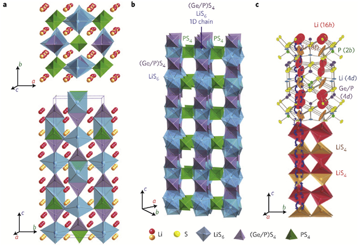
Figure 6. Schematic for the crystal structure of Li10GeP2S12. 24 (a) Framework structure and Li-ions responsible for ionic conduction. (b) One dimensional chains of the framework structure shown in (a). (c) Pathways for lithium ion conduction.
Download figure:
Standard image High-resolution imageLater, to enhance the ionic conductivity of Li10GeP2S12, it was doped with oxygen and chlorine. Chlorine doped Li10GeP2S12 i.e. Li9.54Si1.74P1.44S11.7Cl0.3 has shown the highest ionic conductivity of 2.5 × 10⁻² S cm−1 at room temperature among all the reported Li-ion electrolytes so far. 86,87 Though, ASSBs are considered promising in terms of energy density for next-generation energy storage systems. Nevertheless, their insufficient ionic and electronic percolation within the composite cathode limits the performance. 88
Lithium is considered the most suitable metal for the anode of high-energy secondary batteries. But the dendrite formation hinders the use of Li metal as anodes with traditional liquid or polymer electrolytes. However, due to high mechanical strength and high Li-ion transference number, the solid-state electrolytes are assumed to be suitable for the prevention of Li dendrite growth. Due to higher ionic conductivity and excellent compatibility with lithium metal anodes, Li7La3Zr2O12 [LLZO] and Li2S–P2S5 is considered the most promising solid-state electrolytes. Nevertheless, recent reports have shown the formation of lithium dendrites in LLZOs and Li2S–P2S5 solid-state electrolytes. 89 With the help of Li NMR chemical shift imaging and electron microscopy, Lauren E. Marbella et al. 90 monitored the primary stages of dendrites growth in the garnet-type solid electrolyte, Li6.5La3Zr1.5Ta0.5O12. The inorganic solid-state electrolytes with their composition, ionic conductivity, and corresponding temperature have been summarised in the Table I below.
Table I. Summary of ionic conductivities of the Inorganic Solid-State Electrolytes at their respective temperatures.
| Solid-State Electrolyte | Composition | Ionic conductivity [S cm−1] | Temperature [K] | References |
|---|---|---|---|---|
| NASICON | LiTi2 [PO4]3 | 2 × 10⁻⁶ | 298 | 91 |
| Li1.3M0.3Ti1.7 [PO4]3 [M = Al or SC] | 7 × 10⁻⁴ | 298 | 91 | |
| Li1.3Al0.3Ti1.7 [PO4]3 | 7 × 10⁻⁴ | 298 | 20 | |
| LiTi2[PO4]3−0.2Li3BO3 | 3.0 × 10⁻⁴ | 298 | 92 | |
| Li1.4Al0.4Ti1.6[PO4]3 | 1.12 × 10⁻³ | RT | 93 | |
| LISICON | Li14Zn [GeO4]4 | 1.25 × 10⁻¹ | 573 | 22 |
| γ-Li14.4 V1.6Ge2.4O16 | ∼10−6 | RT | 17 | |
| Li3.6Ge0.6V0.4O4 | 4 × 10⁻⁵ | 291 | 94 | |
| Li3.34P0.66Ge0.34O4 | 1.8 × 10⁻⁶ | 313 | 95 | |
| Li10.42Si1.5P1.5Cl0.08O11.92 | 1.03 × 10⁻⁵ | 300 | 96 | |
| Li10.42Ge1.5P1.5Cl0.08O11.92 | 3.7 × 10⁻⁵ | 300 | 96 | |
| Li3.53[Ge0.75P0.25]0.7V0.3O4 | 5.1 × 10⁻⁵ | RT | 97 | |
| Perovskite | Li0.34[1]La0.51[1]TiO2.94[2] | 2 × 10⁻⁵ | RT | 28 |
| LiSr1.65Zr1.3Ta1.7O9 | 1.3 × 10⁻⁵ | 303 | 98 | |
| Li3/8Sr7/16Ta3/4Hf1/4O3 | 3.8 × 10⁻⁴ | 298 | 99 | |
| Li3/8Sr7/16Nb3/4Zr1/4O3 | 2 × 10⁻⁵ | 303 | 100 | |
| Li3/8Sr7/16Nb3/4Zr1/4O3 | 1.98 × 10⁻⁵ | 303 | 101 | |
| Li0.25La0.583TiO3 | 4.53 × 10⁻⁴ | 293 | 102 | |
| Anti-perovskites | Li3OCl | 0.85 × 10⁻³ | RT | 34 |
| Li3OCl0.5Br0.5 | 1.94 × 10⁻³ | RT | 34 | |
| Garnets | Li3Nd3Te2O12 | 1 × 10⁻⁵ | 873 | 39 |
| Li5La3Nb2O12 | 8.0 × 10⁻⁶ | 295 | 40 | |
| Li6BaLa2Ta2O12 | 4 × 10⁻⁵ S cm−1 | 295 | 42 | |
| Li7La3Zr2O12 | 3 × 10⁻⁴ | 298 | 43 | |
| Li6.5La2.5BaZrTaO12 | 6 × 10⁻³ | 373 | 44 | |
| Li6.55Ga0.15La3Zr2O12 | 2.06 × 10⁻³ | RT | 45 | |
| Li6.5La3Zr1.5Ta0.5O12 | 0.75 × 10⁻³ | RT | 103 | |
| Li6.25La3Zr2Al0.25O12 | 0.68 × 10⁻³ | RT | 103 | |
| Li6.25La3Zr2Ta0.25Ga0.2O12 | 1.04 × 10⁻³ | RT | 103 | |
| Amorphous/glass | Li3.3PO3.9N0.17 | 2 × 10⁻⁶ | 298 | 43 |
| Li0.29S0.28O0.35N0.09 | 2 × 10⁻⁵ | RT | 59 | |
| 0.3 liBO2–0.7 li2SO4 | 2.5 × 10⁻⁶ | RT | 61 | |
| Li2.9Si0.45PO1.6N1.3 | 1.24 × 10⁻⁵ | RT | 62 | |
| Li3+xSixP1−xO4 | 2.06 × 10⁻⁵ | RT | 104 | |
| Li2S-SiS2 based | Li2S-SiS2 | 5 × 10⁻⁴ | 298 | 64 |
| 0.03Li3PO4−0.59Li2S-0.38SiS2 | 6.9 × 10⁻⁴ | RT | 65 | |
| 95 [0.6Li2S − 0.4SiS2]. 5Li4SiO4 | ̴ 10−3 | RT | 66 | |
| 95[0.6Li2S0.4SiS2].5LixMOy [M = Si, P, and Ge] | ̴ 10−4 | RT | 67 | |
| Li2S-P2S5 based | Li2S-P2S5 | 3 × 10⁻⁶–1.6 × 10⁻⁴ | - | 105 |
| 0.23B2S5−0.10P2S5− 0.67Li2S | 1.41 × 10⁻⁴ | RT | 72 | |
| 70Li2S-30P2S5 [Glass, Mechanical Milling] | 5.4 × 10⁻⁵ S | RT | 74 | |
| 70Li2S-30P2S5 [Glass Ceramic, Mechanical Milling] | 3.2 × 10⁻³ | RT | 74 | |
| 70Li2S-30P2S5 [Ceramic, Solid State Reaction] | 2.6 × 10⁻⁸ | RT | 74 | |
| 70Li2S-30P2S5 | 1.7 × 10⁻² | 298 | 78 | |
| 75Li2S-25P2S5 [Glass] | 2 × 10⁻⁴ | 298 | 71 | |
| 75Li2S-25P2S5 [Glass-ceramic] | 2.8 × 10⁻⁴ | RT | 105 | |
| 0.23B2S5−0.10P2S5−0.67Li2S | 1.41 × 10⁻⁴ | 298 | 72 | |
| thio-LISICON | Li4.275Ge0.61Ga0.25S4 | 6.5 × 10⁻⁵ | 298 | 80 |
| Li3.25Ge0.25P0.75S4 | 2.17 × 10⁻³ | 298 | 82 | |
| Li10GeP2S12 | 1.2 × 10⁻² | 300 | 24 | |
| Li10SnP2S12 | 7 × 10⁻³ | 300 | 85 | |
| Li9.54Si1.74P1.44S11.7Cl0.3 | 2.5 × 10⁻² | RT | 87 | |
| Li3.25Si0.25P0.75S4 | 1.22 × 10⁻³ | RT | 106 | |
| Other | Li7P2S8I | 6.07 × 10⁻³ | RT | 107 |
| Li15[PS4]4Cl3 | 4.0 × 10⁻⁸ | RT | 108 | |
| Li14.8Mg0.1 [PS4]4Cl3 | 2.0 × 10⁻⁷ | RT | 108 | |
| Li10SiP2S11.3O0.7 | 3.1 × 10⁻³ [107] | RT | 109 | |
| LiTa2PO8 | 1.86 × 10⁻⁴ | 298 | 102 |
Recent Efforts to Enhance SSE Properties
It includes enhancing the ionic conductivity, enhancing the voltage stability window, suppressing the dendrite formation, and minimizing the interfacial resistance between electrolyte and electrode. 110
The ionic conductivity of SSEs depends on the carrier concentration, 38 crystal structure, 16,24,26,51 and migration-energy barrier. 111 In general, at the state of optimum carrier concentration, maximum ionic conductivity is achieved as this state is abundant with the ionic carriers and vacant hopping sites. The SSEs with highly distortable lattice also exhibit enhanced ionic transportation via disturbing the ionic arrangement and abolishing the degeneracy of transport barriers. However, wide-ranging distortions cause diminished thermodynamic stability as well. 112
Figure 7 shows the voltage stability window of an electrolyte. It refers to the voltage range of the electrolytes between which it can operate without redox decomposition. In thermodynamics, it is defined by considering the free energy of the decomposition reactions as a function of voltage. 113 A voltage beyond the thermodynamic stability limit i.e. "overpotential" is required to trigger the atomic rearrangements, which is usually associated with decomposition. It is strongly linked with the ionic transportation in SSEs as it explains the tendency for most SSEs to decompose when kept in close contact with electrodes. 113,114 In SSEs the upper limit of voltage oxidation stability depends on the anion framework, particularly on their tendency to lose the electrons which are usually restricted by the anion with minimum ionization potential obeying the order N3− < P3− < H− << S2− < I− < O2− < Br− < Cl− << F−. Reversely, the voltage reduction stability of SSEs depends on their tendency to accept the electrons i.e. the electron affinity of non-mobile cations, which is largely affected by structure and bonding features. 115–117
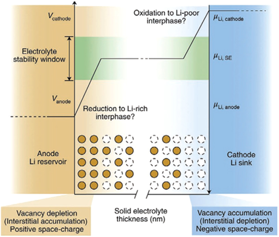
Figure 7. Evolution of chemical potential across the SSEs in contact with an anode and a cathode. The y-axes denote the voltage (V, increasing) and the chemical potential (μ, decreasing) of the mobile cation as a function of the solid electrolyte (SE) thickness on the x-axis. 113
Download figure:
Standard image High-resolution imageThe lithium-ion batteries using lithium (Li) metal as anode instead of graphite have shown ultrahigh specific capacity (3860 mAh g−1) and minimum electrochemical potential (−3.04 V) (for graphite anode: 372 mAh g−1 and 0.1 V). However, these are still miles away from the practical application because of uncontrollable dendrite formation during charging-discharging cycles. The dendrites cause serious safety hazards, poor life span, and rapid capacity decay in lithium (Li) metal anode-based lithium-ion batteries. 113,118,119 Being low in modulus, the polymer electrolytes are unable to inhibit dendrite growth. Inversely, being high in mechanical strength and compactness, SSEs are expected to forbid the dendrite penetration through them and prevent short-circuit.
Unfortunately, apart from the dendrite formation from lithium metal anode and their penetration through polymer and solid-state electrolytes (Fig. 8), recent reports have suggested that Li dendrites form inside SSEs themselves. It is even worse as the short circuit starts at currents of lower magnitude as compared to the liquid or polymer electrolytes. 119–126 However, the mechanism of Li dendrite formation in SSEs is yet to be understood fully. Though, poor electrode/electrolyte interfacial contact, electronic conductivity of bulk SSEs, and grain boundaries are supposed as the cause of dendrite growth in SSEs. 125 To suppress the Li dendrite growth in SSEs, Xiao Ji et al. came with the idea of higher ionic conductivity and low electronic conductivity in SSEs. Also, thermodynamically stable SSEs with Li have shown dendrite suppression capability. 127
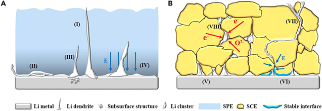
Figure 8. Schematic illustrating the dendrite growth mechanism in organic solid polymer electrolyte (A) and inorganic ceramic/glass electrolyte (B). 126
Download figure:
Standard image High-resolution imageThe interfacial resistance between SSEs and electrodes plays a crucial role in the ASSBs performance. Despite significant enhancement in the ionic conductivity of SSEs, poor interfacial resistance limits overall ASSBs performance. In principle, the solid interface (Fig. 9) formed between SSEs and electrodes should be favorable for the transportation of electrons and ions as well. The heart of ASSBs i.e. the interface involves the concepts of physics, chemistry, and mechanics which makes it challenging to understand. Though, in previous years researchers have made a huge effort to understand the interfacial resistance and overcome the challenges encountered. 128–130

Figure 9. Schematic representation of a bipolar-stacked solid-state battery cell. Insets are magnified sections that highlight the three main challenges facing solid-state batteries with metal anodes: (1) inhomogeneous metal deposition, (2) formation of blocking interface, and (3) contact loss on electrochemical cycling. 113
Download figure:
Standard image High-resolution image
To avoid side reactions in seek of the promising interface, boron nitride-like chemically inactive compounds have been used in conjugation with a polymer. 131 Similarly, a 3D crosslinked gel polymer-based interface layer can mitigate overstretch between NASICON based SSE, Li1.3Al0.3Ti1.7(PO4)3 (LATP) and Li metal. 132 Also, to avoid unnecessary reactions between Li and the SSEs, LiTFSI (TFSI− = bis (trifluoromethane) sulfonamide) dioxolane–dimethoxyethane electrolytes 133 or spin-cast phosphoric acid of molarity one is introduced on Li foils to react with LGPS (Li10GeP2S12) and Li metal. 134 In an emerging strategy, the interface reactions have also been used in building a self-repairing interface if damaged. 135 In garnet-based ASSBs higher interfacial resistance is tackled by using molten Li anode-like deformable electrodes, 136 which are used to store grid energy at intermediate temperatures (240 °C).
In order to fabricate oxide based All Solid State Lithium ion Battery, Okumura et al. used LISICON based amorphous LGPO (Li3.75Ge0.75P0.25O4) solid state electrolyte with Li3BO3 additive and NMC (LiNi1/3Mn1/3Co1/3O2) / Li metal as cathode/anode. With large capacity degradation, the cold pressed ASSB showed the reversible capacity of the NMC positive electrode at 60 °C. 137–139 In a recent approach, Yao et al. utilized infiltration of inorganic electrolyte at elevated temperature into the matrix of dense and thermally stable solid state electrodes for scalable synthesis of economically viable ASSB. 140 Another recent work for making workable solid state battery proposed by Mao Shoji et al. which is based on 3D structured cell configuration such as interdigitated combination of 3D pillars of cathode and anode. The realization of such cell can be achieved by using solid electrolyte membrane in hole-array configuration. 141 Recent work of Min Ju Kim et al. discussed the adverse side reactions of the sulphide based solid state electrolyte with polar solvents during the fabrication of ASSB by usual slurry process. They further proposed solution based process for homogeneously distributing the solid electrolytes in porous solid electrodes by efficient infiltration methods. 142
Conclusion and Future Scope
This review is based on inorganic solid-state electrolytes for all solid-state Li-ion batteries, showing the ionic conductivity of few solid-state electrolytes, such as thio LISICONs, comparable to that of organic liquid electrolytes. However, their compatibility with moisture, air, and Lithium electrodes is still challenging and therefore is far away from application in ASSBs. Also, for anti-perovskites, the ambient atmosphere is an even bigger challenge. LISICON and thin-film Li-ion conductors such as LiPON show poor ionic conductivities, though LiPON phases are being used in micro-batteries. With fair ionic conductivities and atmospheric stability, NASICON, garnet, and perovskite-type solid-state electrolytes seem good for their applications in ASSBs. For the advancement of battery performance, the investigation to improve the ionic conductivity of solid electrolytes and their compatibility with electrodes and atmosphere is certainly worthwhile.
The lithium-ion batteries based on inorganic solid-state electrolytes are believed as the future of electric vehicles, hybrid electric vehicles, and grid energy storage. Though, the Inorganic solid-state electrolytes with higher ionic conductivity, higher electrochemical stability, excellent mechanical stability, and low activation energy require the exploration of new compounds and structures. The fundamental understanding of such compounds and structures requires advanced theoretical calculations along with high-throughput computational modeling and experiments.
To probe the structures of novel compounds, the use of atomic-scale characterization will be enhanced. To enhance the energy/power density of ASSBs the use of nano-materials will be increased. However, the inclusion of nano-materials in ASSBs creates the large number of electrolyte–electrode interfaces. Unlike single bulk materials, our knowledge about ionic conduction through the interfaces is limited. Therefore novel computational and experimental techniques will be required to monitor ASSBs operation.
The use of nano-materials in ASSBs causes a limited contact area between SSEs and electrodes. It in turn results from higher electrolyte-electrode resistance. To fight electrolyte-electrode incompatibility three strategies may be adopted- (1) Application of artificial coating layer between electrolyte-electrode interfaces. (2) Enlargement of the electrolyte-electrode contact area. (3) Concept of Single phase ASSBs.
Acknowledgments
The authors would like to thank the Department of Science and Technology (DST) & Science and Engineering Research Board (SERB), Government of India under project no. DST/TMD/MES/2017/32(G) and CRG/2018/002067 respectively. The authors are also grateful to Pandit Deendayal Energy University (PDEU) for providing the necessary facilities to carry out this investigation. Financial support from Solar Research and Development Center (SRDC) and PDEU is deeply acknowledged.