

Abstract
We have investigated the effect of ionic liquids (ILs) additives in 1 M LiTFSI in 1,3-dioxolane (DOL)/dimethyl ether (DME) (1:1, v/v) on the solid electrolyte interphase (SEI) using a combined theoretical and experimental method for next-generation Li metal batteries. Among all investigated cations of ILs including imidazolium (IMI+), pyrrolidinium (PYR+), and piperidinium (PIP+) cations, we have observed that the presence of IMI+ provides relatively larger decomposed products of the TFSI anion on the Li metal surface when compared with saturated-ring type cation ILs including PYR+- and PIP+-ILs due to its high electron affinity (EA). Furthermore, the reactive molecular dynamics results show that the SEI layer of the system using the ILs with saturated rings is significantly thin when compared to that of the ILs with aromatic-ring, which is desired for fast Li-ion diffusivity through the SEI. This finding may lead to an ideal design of electrolyte system for future Li-metal batteries.
Export citation and abstract BibTeX RIS
Lithium (Li) metal is an attractive anode material for next-generation rechargeable batteries due to its high theoretical specific capacity (3860 mAh g−1). Unfortunately, practical applications of Li metal in the rechargeable batteries have been limited due to its poor cycling capability and severe safety issues. When increasing cycle numbers, the metallic Li dendrite can penetrate through the polymer separator leading to the short circuit and eventually the explosion of batteries. To address this issue, researchers have been attempting to stabilize the solid electrolyte interphase (SEI) layer via many approaches including modification of electrolytes and addition of electrolyte additives.
One of the promising approaches is to use room-temperature ionic liquids (RT-IL) for enhancing the stability of the Li batteries by forming the stable and resilient passivation layer at the SEI. 1–3 Over the past decades, various studies have created a general picture of the SEI mechanism. 4–6 The cation and anion of ionic liquids (ILs) play different roles in controlling the stability of Li metal anode. The anions of lithium-based electrolytes can improve the mechanical properties of SEI by providing the decomposed compounds including LiF and Li2O within the SEI layer. 7,8 One of the most common ILs used in LIBs is pyrrolidinium-based bis(trifluoromethanesulfonyl) imide (PYR+/TFSI-). By using X-ray photoelectron spectroscopy (XPS), P. C. Howlett et al. found that the TFSI- ions are decomposed forming LiF, Li2O, LiOH, Li2S2O4, and LiyC2Fx compounds on the Li anode. 9 Besides, the PYR+ cation induces the electrostatic shielding and lithiophobic effects controlling the Li-ion flux on the anode surface, 10 which improves the deposited lithium morphology. 3,10,11 Moreover, the length of the nonpolar aliphatic chain attached to the cation ring can be extended. The extended ILs cation (Pyr1 12 ) exhibits less thickness of the dead lithium layer and can suppress Li dendrite growth when compared to the Pyr1 4 cation because of more lithiophobic effect of the longer aliphatic chain. 10 Besides, the piperidinium and pyrrolidinium-based cations could be a better option in controlling the lithium dendrite formation compared to imidazolium-based cation due to the higher tolerance of the saturated-ring type to undergo electrochemical reaction on lithium metal surface. 12 Despite these reports, the interplay between cation type and the reaction mechanisms of SEI formation have not yet been fully investigated and understood. Herein, we have investigated the mechanism of SEI formation in 1 M LiTFSI in 1,3-dioxolane (DOL)/dimethyl ether (DME) (1: 1, v/v) mixture with TFSI-based ILs of three different cations, i.e., 1-butyl-3-methylimidazolium-(BIMI-), 1-butyl-3-methyl pyrrolidinium-(BPYR-), and 1-butyl-3-methyl piperidinium-(BPIP-) (see Fig. 1). Based on our experimental and theoretical investigation, we have proposed the SEI formation mechanism according to the decomposition of the ILs on the Li anode surface. Besides, we have theoretically discussed the effect of IL cations and experimentally investigated the Li/Li symmetric cell configuration with different electrolyte ILs additives.

Figure 1. Chemical structures of different 6 ionic liquids with different cation types by fixing an anion TFSI−.
Download figure:
Standard image High-resolution imageExperimental
Theoretical simulation
Theoretical reactive molecular dynamics (RMDs) simulation using the reactive force-field (ReaxFF) computational package was used as a tool for studying and predicting the chemical reaction between the electrolyte and the Li anode. The Reactive Force Field (ReaxFF) simulation was investigated using the atomistic force-field method for the relations between C, H, O, S, Li, F, P and N atoms. The interactions were trained for lithium (metal) battery materials. 13,14 A simulated cell was constructed with two regions including a lithium metal anode and a liquid electrolyte region (see Fig. S1 available online at stacks.iop.org/JES/168/040534/mmedia). The lithium anode was constructed from the Li body-centred cubic (bcc) structure with a lattice parameter of 3.490 Å. The bulk structure was cut along the (100) directions to build a surface slab with cell parameters of 55.8 Å × 27.9 Å × 69.8 Å. The periodic boundary condition (PBC) was applied along the X and Y directions where the bottom 4 layers of Li(100) were fixed at bulk position. The elastic wall was also built at Z = 0 Å to avoid the interaction between the bottom surface of Li(100) and electrolyte components due to PBC in Z-direction. The electrolyte components were packed using PackMol. After assembling all of regions, the simulation cell parameters were changed to 55.8 Å × 27.9 Å × 169.8 Å. Different solvent molecules were used (see Fig. 1). The reactions between anode and electrolyte components take place on the top of Li(100) surface. The simulations were carried out with a canonical ensemble at the constant number of particles N, volume V, and temperature T (NVT) with the Nosé-Hoover chain (NHC) thermostat with a damping parameter of 100 fs-1. The time step of 0.5 fs and the temperature of 298 K were applied for entire RMD simulations.
All the electronic and stability properties were computed using the accuracy of the range-separated, dispersion corrected ωB97XD functional. 15 All the DFT geometries were optimized for each of the functionals with the 6-311++G(2d, 2p). The energy gap was calculated from the difference between the HOMO and LUMO energies, Eq. 1:

The Ionization Potential (IP) and Electron affinity (EA) were calculated from Eqs. 2 and 3, respectively.


where EN, EN−1, and EN+1 are the ground-state energies of the N, N − 1, and N + 1 electron-containing systems, respectively.
The density functional theory (DFT) investigations in this article were performed by the Gaussian16 computational package09. Full optimizations, geometries and property calculations for the total energies were accounted and unrestricted by the hybrid meta generalized gradient approximation (meta-GGA) 16 with the accuracy of the range-separated, dispersion corrected ωB97XD functional. The polarized double ζ basis set 6-311G(2d, 2p) was set for all atoms. The convergence threshold for self-consistency-field (SCF) was set at 10−6 Hartree. All stationary points were characterized as no imaginary frequencies by the calculation using the same level of theory. The calculated relative binding (Eb ) energies were defined as a following Eq. 4:

where Et, EILs,cation and EILs,anion are the total energies of the ILs, Cation ILs, and Anion ILs molecules, respectively.
In this investigation, we have examined different 6 ILs cation types by fixing the bistrifluoromethanesulfonylimide as the anion (see Fig. 1). This extensive selection of ions includes cation families, such as pyridinium, imidazolium and piperidinium.
Synthesis of ionic liquids
The synthesis of ionic liquids is generally composed of 2 steps. The first step is the cation formation. N-methylimidazole, N-methylpyrrolidine and N-methylpiperidine were used as precursors for imidazolium, pyrrolidinium and piperidinium cations, respectively. 0.12 mole of N-methylimidazole (10.0 ml), N-methylpyrrolidine (12.4 ml) and N-methylpiperidine (14.5 ml) were dissolved in acetonitrile. The different alkyl chain lengths including ethyl, propyl, butyl and pentyl chains were introduced to each cation structure by adding 0.12 mole of 1-bromoethane (13.3 ml), 1-bromopropane (16.4 ml), of 1-bromobutane (19.4 ml) and of 1-bromopentane (22.3 ml) into the solutions. The solutions were refluxed at 100 °C for overnight. The mixtures were purified by washing with diethyl ether (DE). The second step is anion exchange. Cation compounds consisting of imidazolium-based bromide, pyrrolidinium-based bromide, and piperidinium-based bromide, were dissolved in deionized (DI) water and then 29 g (0.10 mol) of lithium bis(trifluoromethanesulfonyl)imide (LiTFSI) was added into the solution. When the reactions finished, two layers of aqueous and organic layers were obtained. The organic layers were washed with DI water to remove the residual reactants checked by no precipitants after adding aqueous silver nitrate (AgNO3) into the rinsed water. The synthetic ionic liquids were dried under vacuum at 100 °C for overnight and kept in Ar-filled glove box. The chemical structures of ionic liquids were characterized the structures by 1H, 13C nuclear magnetic resonance (1H and 13C NMR) (Bruker, ascent 600) and atmospheric pressure chemical ionization (APCI) mass spectrometer (Compact QTOF, Bruker).
Electrochemical evaluation
The electrochemical performances of Li/Li symmetric cells with different ILs were performed in an argon-filled glovebox using 2032-type coin cells with lithium metal chip, poly(ethylene) (PE; Celgard 3501) membrane was used as a separator. The 10 %wt electrolyte ILs of BIMITFSI, BPYRTFSI and BPIPTFSI were used as additives. Each IL was mixed with 1 M bis(trifluoromethane)sulfonimide lithium salt (LiTFSI; Aldrich, 99.95%) in 1:1 v/v of 1,3-dioxolane (DOL; Aldrich) and 1,2-dimethoxyethane (DME; Aldrich) mixture solvents. All coin cells were made with 40 μL of electrolyte volume. The galvanostatic charge/discharge measurements were performed on NEWARE BTS-CT3008 (Neware Technology, Shenzhen, China) at a constant current density of 1 mAh cm−2 for 1 h or 1 mA cm−2.
Results and Discussion
To understand the effect of ILs on the Li metal surface, we have firstly investigated the chemical interaction between the Li and BIMITFSI-based ionic liquid with various simulation times (1 ps to 100 ps) as shown in Fig. S2 of the supporting information (SI). BPYRTFSI and BPIPTFSI were also studied as shown in Figs. S3 and S4, respectively. Note that the simulations were carried out at an open-circuit voltage (OCV) condition. The BIMITFSI-ILs molecules are randomly placed on the Li(100) surface with a density of about 0.80 g cm−3. The simulation shows that the Li anode is rapidly consumed whenever it is brought into contact with the electrolyte indicating that it is very reactive. The Li atom is oxidized to Li-ion having an average calculated charge of +0.668. The electrolytes are decomposed producing a new phase called the porous phase 5 including the disperse phase and the nest phase 17 (Figs. S2-S8). Both phases are normally expanded over the simulation time, which is consistent with the experimental observation from the literature. 18 The characteristics of these phase regions are identified by using the Li-Li Radial-pair distribution (RPDF) (Fig. S3). The nest and disperse phases exhibit the liquid-like structure, whereas the dense phase (bulk Li) is identified as the solid structure. The RPDF of the nest phase shows the sharpest peak at 3.15 Å and a subsequent peak with a small fluctuation, which is a characteristic peak of an amorphous-like structure.
Figure 2 compares the simulated system results at the OCV of BIMITFSI (Fig. 2a), BPYRTFSI (Fig. 2b), and BPIPTFSI (Fig. 2c) at the Z-direction starting from the Li metal surface to the SEI layer at the middle and eventually to the bulk IL phase. The as-formed compounds in the layers are shown in Fig. 2d. In the absence of ILs, TFSI anions react with the Li metal at the surface producing NSO2CF3 and SO2CF3. This compound can be further reduced on the Li surface to inorganic compounds including LixO and LixF as well as N2. This result is like the previous work. 8,17 LiF, Li2CO3 and Li2O spontaneously occur as SEI compounds due to the decomposition of F-based electrolytes at the Li surface. 19,20 Interestingly, the IL cations play a major role in the decomposition process of the TFSI anion at the SEI due to different electrostatic forces in the system leading to different SEI compositions and morphologies. Eventually, this phenomenon affects the electrochemical performance and stability of Li-metal batteries. Figure S9 shows a comparison of IL cations between 0 and 100 ps simulation time, in which the systems are already in the steady state. Due to the RMS force (See Fig. S10), the interactions between molecules are stable for all three systems at around 70 ps. The results show no decomposition of BIMI, BPYR, and BPIP cations within the porous phase, which is consistent with the AIMD simulation result in other systems. 21 In addition, the presence of stable cation species in the electrolyte system can form a positively charged electrostatic shielding for suppressing lithium dendritic growth. 3,10,11 Moreover, the thicknesses of the formed passivation layer at the SEI (z-direction) of BIMITFSI, BPYRTFSI, and BPIPTFSI at 100 ps are 54 Å (Fig. 2e), 39 Å (Fig. 2f), and 37 Å (Fig. 2g), respectively. The passivation layer of saturated rings of ILs including BPYRTFSI and BPIPTFSI is significantly thin when compared to aromatic-ring ILs (BIMITFSI), which is desired for Li-ion diffusivity in the SEI interphase. 6 Thus, the ILs could play a major role for suppressing Li dendrite formation, which is a major issue of Li-metal batteries. Moreover, the calculated charge of Li ion near the outer surface of the SEI can be confirmed by a restrained electrostatic potential (RESP) charge calculation using the DFT/B3LYP/6-31 G(d,p) level. The calculated charge of Li ion near the outer surface of the SEI is +0.696 (See Fig. S11), which is close to the ReaxFF predicted result. This Li + species are in the SEI compound, which is not the metallic lithium (Li0).

Figure 2. Simulation snapshots of atomic charge distribution at a simulation time of 100 ps with pure ionic liquids including (a) BIMI-TFSI (b) BPYR-TFSI and (c) BPIP-TFSI ILs as well as (d) the as-formed products relating to the decomposition of the electrolytes with and without ILs additives, i.e., BIMI-TFSI, BPYR-TFSI and BPIP-TFSI ILs at the Li anode. The Li atom densities of BIMI-TFSI, BPYR-TFSI and BPIP-TFSI in the Z-direction are shown in (e)–(g), respectively.
Download figure:
Standard image High-resolution imageTo understand the effect of the cations on the decomposition of TFSI anion, the electronic structure of those ILs was investigated using the density functional theory (DFT) calculation. The calculation result is listed in Table SI. The electron affinity (EA) values of BIMI-IL, BPYR-IL, and BPIP-IL cation are 3.65, 2.33, and 2.22 eV, respectively. This is in good agreement with the previous works. 22,23 The BIMI-IL cation exhibits higher EA as compared to others indicating that the BIMI-IL cation does preferably accept electrons as compared to the other saturated cations. The BIMI+ contains the charge delocalization aromatic-ring structure that can reduce the electrostatic interaction between BIMI cation and TFSI anion. 24 Then, the presence of BIMI-ILs provides relatively large decomposed products of the TFSI anion on the Li metal surface when compared with BPYR-IL and BPIP-IL.
For a better understanding of the effect of cations, the influence of the alkyl side chain length on the cation molecule was also investigated. This section focuses on the pyrrolidinium-based cation (CnmPYR) with various alkyl-side chain lengths (n = 2 to 5) on the N2 position of cation-ring ILs. By using the ReaxFF calculation, the products from the electrolyte decomposition at 100 ps are shown in Fig. S12a. As the constituent alkyl chain length of the pyrrolidinium-ILs increases from ethyl- to butyl-side chain cations (from n = 2 to n = 4), the as-formed LixNSOyCFz and LinSOyCFz products are decreased. The pentyl-side chain cation (n = 5) does not provide any significant difference between these products in terms of their quantities, but it generates higher gases than the other. The effect of these side-chain lengths is further explained via the ion-pair binding energy and EA. The ion-pair binding energy is used to determine the side conformation (Conf-2N). The interaction between ion pairs consists of both electrostatic and hydrogen bonds. 25 In Fig. S12b, the ion-pair binding energies of CnmPYRTFSI (n = 2, 3, 4 and 5) are 3.398, 3.516, 3.602, and 3.601 eV, respectively. Increasing alkyl chain lengths from ethyl to butyl results in higher binding energy. The as-calculated EA is listed in Table SI. The EA values of CnmPYRTFSI (n = 2, 3, 4 and 5) are 2.4027, 2.3528, 2.3346, and 2.3165 eV, respectively. 23 The decreasing alkyl side chain lengths provide lower ion-pair binding energy and higher EA. The latter implies that CnPYRTFSI (n = 2) is more readily reduced as compared to its derivatives with longer alkyl chains.
The 10 %wt. IL additive was added to 1.0 M LiTFSI in 1:1 v/v DOL/DME electrolyte, which is widely used for Li-metal batteries such as Li-S. 17,26 The as-formed compounds are shown in Fig. 3 . In the absence of ILs, the DOL/DME molecules are mainly decomposed forming lithium alkoxide (LiOR) and oligomers with -OLi groups at the disperse phase. The LiOR compound can further react with LixNSO2CF3 and LixSO2CF3 to generate LixO, LixCF3, LixNOy, and N2 gas. More details have been explained in the previous work. 17 After adding ILs, other different chemical compositions are not observed in both nest and disperse phases. This is consistent with the previous work. 10 However, the amount of LiOR molecules significantly decrease while those of both LixNSO2CF3 and LixSO2CF3 molecules increase. The higher concentration of TFSI anion makes the location of LUMO shift form the solvent towards the anion, 27 resulting in higher TFSI anion decomposition product. Moreover, the TFSI fractions can be reduced on the Li metal to generate the inorganic compounds such as LixF and LixO, leading to the thinner and more protective SEI. 28,29 Thus, not only does the cation ring-type affect the TFSI anion decomposition due to the differential of electron affinity (EA), but the TFSI anion concentration does also affect the TFSI anion decomposition. 30 The neighbouring molecules influence the as-formed products especially LixSO2CF3, which can be observed in Figs. 2d and 3. Besides, the cations directly diffuse to the lithium surface over the simulation time without randomly walking (see Fig. 4a). During the decomposition of TFSI anion on the surface of lithium, the cations are dissociated and accumulated on the interphase, in the nest and disperse phases. The cations could induce smooth and dendrite-free morphologies on the Li electrode, which is the characteristics of the electrostatic shielding effect of cations against Li-ions as mentioned elsewhere. 10,11

Figure 3. Chemical products from the SEI formation at the Li anode with different IL cations in LiTFSI in DOL/DME (1:1,v/v).
Download figure:
Standard image High-resolution image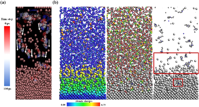
Figure 4. (a) The trajectory of BPYR cation in LiTFSI/DOL/DME/BPYRTFSI at the Li surface with a simulation time of 0 to 100 ps. (b) A simulation snapshot of atomic charge distribution, cell components and BPYR cation, respectively in LiTFSI/DOL/DME/BPYRTFSI at a simulation time of 100 ps.
Download figure:
Standard image High-resolution imageIn addition, the effect of IL electrolyte additives was experimentally investigated using Li/Li symmetric cells. As shown in Fig. 5, the Li/Li symmetric cells were tested in 1 M LiTFSI in DOL/DME, 1 M LiTFSI in DOL/DME + 10 %wt. BIMITFSI-IL, 1 M LiTFSI in DOL/DME + 10 %wt. BPYRTFSI-IL, and 1 M LiTFSI in DOL/DME + 10 %wt. BPIPTFSI-IL. The galvanostatic cycling voltage profiles show the symmetric electrochemical behavior during charge-discharge cycles for the first few cycles due to the SEI formation. 31 The unstable voltages can be observed in the system without the IL additive after 350 cycles due to the large polarization relating to the electrolyte depletion. 32 In the presence of the IL additives, the profile can maintain more stable voltage with small polarization (>480 cycles). Figure 6 shows the FESEM images of deposited lithium surface electrodes after the 60th charge-discharge cycle (120 h) with and without BIMITFSI, BPYRTFSI, and BPIPTFSI additives. The results clearly show that the surface morphology of the system using 1 M LiTFSI DOL/DME is more porous than the system with additives. This high-surface area morphology continuously consumes the electrolyte leading to poor capacity retention. However, the presence of ILs additives in the electrolyte systems provide a more dense and smooth lithium deposit on the electrode surface, which is corresponding to the literature. 10 The change of deposited Li morphology is contributed by the chemical composition of the SEI layer especially for the lithiophobic species (ILs cation) as confirmed by the XPS spectra. 3,10 It has been found that the IL cations can provide an electrostatic shielding effect to uniformly distribute the Li-ion flux over the electrode. 10 Previously, the effect of the electrolyte using different IL-cation types was also investigated. From the XPS result, the peak of F 1s branch shows that LiF has less intensity in the case of Pyr1(4)TFSI compared to Im1(4)TFSI. 10 The different formation of LiF-rich is related to the cation ring-type. The high concentration of the stiff LiF species, which is undesirable in the SEI layer of BIMITFSI and BPIPTFSI systems, could be a reason that the SEI layer is cracked during charging/discharging due to the volume expansion of lithium anode. Thus, the system containing BPYRTFSI shows relatively small polarization as compared to others owing to the more flexible SEI layer. The insight into details will be described in the next section.

Figure 5. The galvanostatic cycling voltage profile of the Li/Li symmetric cell behavior of 1 M LITFSI in DOL/DME (Black), with 10 %wt of BIMITFSI-ILs (Blue), with 10 %wt of BPYRTFSI-ILs (Red) and with 10 %wt of BPIPTFSI-ILs (Green) electrolyte system over 950 cycles at a constant current of 2 mAh.cm−2 (1 mA cm−2).
Download figure:
Standard image High-resolution image
Figure 6. FESEM images (Top view) of 1 M LiTFSI DOL/DME (a)–(c), 1 M LiTFSI DOL/DME +10 %wt BIMITFSI (d)–(f), 1 M LiTFSI DOL/DME +10 %wt BPYRTFSI (g)–(i) and 1 M LiTFSI DOL/DME +10 %wt BPIPTFSI (j)–(l).
Download figure:
Standard image High-resolution imageTo gain further insight into the effect of IL additives, the evolution of the lithium electrode surface was investigated (see Fig. S15). The change in the voltage shape is related to the electrode stability and failure. 32 As a result, the transition from the peaking behaviour to the arcing behaviour of the system using 1 M LiTFSI DOL/DME without IL additives appeared much later when compared to the system having ILs. The dense and smooth surface electrode could prevent lithium-ion transport through the interphase resulting in the overpotential established (see Fig. 6). Thus, adding ILs in the ether-based electrolyte system affects the morphology evolution of the lithium surface for which the round shape of dendrite growth is observed instead of needle-like dendrite growth. 10,11
Moreover, the mass transport of lithium ion was investigated using the cycle-to-cycle evolution of voltage tail technique for observing the relaxation of Li-ion concentration (see Fig. 7). The voltage tails become larger during cycling, indicating that the overpotential correlated with mass transport becomes larger due to the dead lithium accumulation. However, in 1 M LiTFSI DOL/DME electrolyte system, the voltage tails become smaller after the 13th cycle. It is possible that the evolution of interphase does not impede ion transport after the 13th cycle due to the porous characteristics of the interphase. This leads to the short-cycle life of the cells. Besides, BPYRTFSI-IL and BPIPTFSI-IL systems show a slight drop of tails during the relaxation relating to the less morphological change of the electrode surface when compared to BIMITFSI-IL. The BIMITFSI system totally drops to the same position as the initial cycle. It causes the rupture or cracking owing to the surface consuming too much electrolyte forming a new mossy dendrite. This relates to the ReaxFF-predicted result (see Fig. 3). The number of LixCO2CF3 is significantly higher as compared to BPYRTFSI and BPIPTFSI. The inorganic-rich species including LiF and Li2O, which are high mechanical strength within the SEI could be the reason for SEI cracking. 33 As the results, the Li-ion diffusion in the saturated-ring type ILs (BPYRTFSI-ILs and BPIPTFSI-ILs) containing electrolyte perform more stable over cycling compared with aromatic-ring type ILs (BIMITFSI-ILs), resulting in more flexible of SEI layer.

Figure 7. The cycle-to-cycle evolution of voltage tails occurring during 3 min rest periods demonstrating the time needed for the Li-ion concentration to relax back to equilibrium conditions of (a) 1 M LiTFSI DOL/DME (b) 1 M LiTFSI DOL/DME +10 %wt BIMITFSI (c) 1 M LiTFSI DOL/DME +10 %wt BPYRTFSI and (d) 1 M LiTFSI DOL/DME +10 %wt BPIPTFSI.
Download figure:
Standard image High-resolution image
Conclusions
The effect of TFSI-ILs additives with different cation types (imidazolium, pyrrolidinium, and piperidinium) was investigated to understand the mechanism of SEI formation. From the RMD simulation and DFT calculation, different electronic properties of cations do affect the reaction mechanism of SEI formation as shown in ReaxFF-predicted results. Among all TFSI-based ILs investigated, the BIMI cation (aromatic-ring type) exhibits the highest electron affinity (EA) generating the highest TFSI anion decomposition products at the SEI layer, resulting in thick SEI. Interestingly, the ReaxFF simulation can be managed to predict the reduction potential, related to electron affinities (EA) of the electrolyte system. From the electrochemical investigation, the aromatic-ring type ILs (BIMITFSI-ILs) containing electrolyte provide the unstable Li-ion diffusion over cycling, caused by SEI cracking. Furthermore, the IL additive was used in the Li/Li symmetric cell exhibiting the stable voltage with a small polarization over 450 cycles. Our results here lead to a more fundamental understanding of the SEI formation mechanism in the Li metal batteries using the IL additives. This finding may be useful for further development of next-generation high-energy Li metal batteries.
Acknowledgments
This work was financially supported by the Thailand Research Fund and Vidyasirimedhi Institute of Science and Technology (RSA6180031) as well as Energy Policy and Planning Office (EPPO), Ministry of Energy, Thailand.