
Abstract
Pt/TiO2 as electrocatalyst was found to significantly increase the rate of the membrane chemical degradation in a polymer electrolyte membrane (PEM) fuel cell. The increased degradation was proved to be due to TiOx (TiO2 or Ti4O7), which is widely recognized as a promising corrosion-resistant electrocatalyst support. The membrane degradation (thinning) appears to be preferentially in the side facing anode electrode. Migrated Ti species as a result of TiOx dissolution during fuel cell operation in an acidic environment was quantified by electron probe microanalysis (EPMA). Total fluorine inventory loss of the membrane strongly depends on the quantity of migrated Ti species (likely Ti3+ and/or Ti4+). The membrane chemical degradation induced by TiOx is proposed to be due to dissolved ionic Ti species reacting with H2O2 through a Fenton reaction. TiOx is determined to be inviable as electrocatalyst support for PEM fuel cells, and future research is suggested to be directed toward alternative oxides with similar corrosion-resistance.
Export citation and abstract BibTeX RIS

This is an open access article distributed under the terms of the Creative Commons Attribution Non-Commercial No Derivatives 4.0 License (CC BY-NC-ND, http://creativecommons.org/licenses/by-nc-nd/4.0/), which permits non-commercial reuse, distribution, and reproduction in any medium, provided the original work is not changed in any way and is properly cited. For permission for commercial reuse, please email: permissions@ioppublishing.org.
Fuel cell electric vehicles (FCEVs) has become a commercial reality, however overall cost reduction as well as durability improvement continue to be the key challenges facing fuel cell developers. One of the areas of durability concern in PEM fuel cells relates to the degradation of carbon supported Pt-based electrocatalysts. 1 Carbon-supported (e.g., Vulcan or Ketjen black) Pt or Pt-alloy (e.g., PtCo) catalysts are commonly used in PEM fuel cells to catalyse the oxygen reduction reaction (ORR) and hydrogen oxidation reaction (HOR). 2 In an automotive environment, the catalysts must survive highly dynamic operations. State-of-the-art high surface area carbon supports suffer from severe corrosion at potentials above 1.1 V. Transient operations contributing to the corrosion of carbon support include vehicle start-up/shutdown, cell reversal due to fuel (hydrogen) starvation, as well as load cycling. 1 Degradation of the carbon support and the electrocatalyst under such operation can induce significant performance decay. Therefore, materials that are inherently more corrosion resistant have been actively investigated as alternative catalyst supports to carbon in PEM fuel cell applications.
In recent years, significant amounts of research effort have been devoted to transition metal oxides such as TiO2 as alternative electrocatalyst supports. 3–12 Titanium oxides become attractive due to their much higher corrosion resistance at high potential, commercial availability and low cost, as well as the controllability of particle size and pore structure. 3 Researchers are also looking for the potential benefits of strong interactions between Pt nanoparticles and the TiO2 support, known as strong metal-support interactions (SMSI), to improve the stability of the supported Pt (Pt-alloy) nanoparticles. 4,5
Oxygen-deficient sub-stoichiometric titanium oxide (such as Ti4O7) has received more attention due to its improved electrical conductivity, which is a typical challenge for metal oxides as electrocatalyst support. In a series of publications, 6–8 Ioroi et al. reported Pt supported on Magnéli-phase Ti4O7 prepared by either high temperature reduction in H2 6 or pulsed UV laser irradiation 7,8 as a corrosion-resistant electrocatalyst support. It was demonstrated that the Ti4O7 supported catalyst shows superior stability in retaining Pt surface area and fuel cell performance compared to carbon supported catalyst in constant high voltage hold 6 or high voltage cycling 7,8 tests that simulate the start-up/shutdown process. Similar benefits were also reported in Pt/TiO2 catalyst in preventing electrochemical oxidation of the catalyst support under high potential and the subsequent detachment/agglomeration of Pt particles. 9
Although the superior corrosion resistance has been repeatedly demonstrated, the initial H2/air performance are generally poor for Pt/TiO2 as electrocatalyst compared to Pt/carbon. 8 Recently, Arai et al. reported significant progress in eliminating the initial performance gap between oxide support and carbon support. 10 In addition to demonstrating the anticipated unmatched corrosion resistance over carbon during high potential hold/cycling, the researchers also achieved same performance when using Pt/TiOx as anode catalyst and Pt/W-SnO2 as cathode catalyst. Such accomplishments further promote TiOx as highly effective corrosion-resistant electrocatalyst support for use in PEM fuel cell.
A second area of durability concern for PEM fuel cell developers are the degradation of the polymer electrolyte membranes which serves as the proton conductor as well as separator for the reactant gases between anode and cathode. Membrane degradation can be mechanical or chemical in nature, causing membrane thinning, pin hole formation, increased gas crossover, and shorting. 13 It has been widely accepted that membrane chemical degradation is primarily due to the formation of hydroxyl radicals that attack the perfluorosulfonic acid (PFSA) membrane back bone and side chain, 14–17 releasing HF, CO2 as well as other small fragments of the fluoropolymer chains. 18 The hydroxyl radical can be generated through Fenton's reaction from H2O2, 15,16 which can be formed in an operating PEM fuel cells. 19 The best-known Fenton's reaction catalyst is Fe2+, therefore, introduction of Fe impurity in any format into PEM fuel cell system as well as the generation of Fe2+ or Fe3+ due to material decay within the fuel cell are being consciously avoided.
Understandably there has been less attention paid to the effect of the interaction of PEM fuel cell material, particularly on long-term durability, by fuel cell component developers or academic institutions, where a specific material function is of primary focus for research and development. However, there is indeed a critical need for fuel cell system developer to ensure mitigation of one failure mode does not compromise the durability of another component or function, e.g., an advanced catalyst or catalyst support should not compromise the chemical durability of PFSA membrane. In this context, we are reporting for the first time the negative impact of TiOx, which has attracted growing attention as promising corrosion-resistant catalyst support, on PFSA membrane chemical durability. Significant degradation of the polymeric membrane is observed in the open circuit voltage (OCV) chemical durability test when Pt/TiO2 is used as electrocatalyst. The impact of the TiOx support is further confirmed by adding trace amount of TiOx in the fuel cell electrode. The extensive fluorine loss from the membrane is manifested in membrane thickness reduction as measured by cross-sectional scanning electron microscopy (SEM). The migration of Ti species in the MEA were analysed by electron probe microanalysis (EPMA). The plausible mechanisms of TiOx-induced PFSA membrane degradation are discussed based on the literature as well as on the observation from this work. Finally, the need to avoid using TiOx as catalyst support in PEM fuel cells is highlighted.
Experimental
MEA fabrication and Open Circuit Voltage (OCV) test in single cell
The MEAs used in this study were fabricated in house. Electrodes are coated directly on gas diffusion layer with either 72.5 wt% Pt/TiO2 or 20 wt% Pt/carbon as the electrocatalyst at Pt loading of 0.05 mgPt cm−2. TiO2 support without Pt or Ti4O7 (Magneli-phase titanium oxide) (Note: TiOx is used in the text to refer to both TiO2 and Ti4O7) were added to electrode coatings with 20 wt% Pt/carbon as the electrocatalyst. Three TiOx loading levels were investigated: 0.33 μgTiOx cm−2 (denoted as 1x loading), 1.32 μgTiOx cm−2 (denoted as 4x loading), 5.28 μgTiOx cm−2 (denoted as 16x loading). These electrode coatings are fabricated into membrane electrode assemblies (MEAs) with 38 cm2 active area and tested as anode (expose to H2) as well as cathode (expose to air) (see illustration in Fig. 1) in a single cell with graphite plates. In all the cases the counter electrodes are the same, with 30% PtCo/C as electrocatalyst at 0.1 mgPt cm−2 Pt loading. The membrane used is a 12 μm PFSA long-side-chain ionomer membrane with expanded PTFE as reinforcement layer and about 8 mol% of H+-sites exchanged by Cerium ions. The MEAs are fabricated by hot-pressing at 295° F, 5000 lb for 2 min, then sandwiched between two graphite plates with 3-path serpentine flow fields as the test cell.
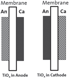
Figure 1. Schematic of the cross-section view of MEA showing the TiOx doping location.
Download figure:
Standard image High-resolution imageThe OCV test on membrane degradation is conducted at 110 °C, 25% RH and 150 kPaabs outlet pressure for both anode and cathode side. The H2/air (anode/cathode) flow rate is set at 270/630 sccm. The exhaust water from both the anode and cathode of the fuel cells was collected by an automatic water collection system. The OCV test runs a total of 100 h, during which 13 water collections were conducted with each collection lasting 2 h and the mass of the water sample is measured. For each MEA type, two single cells were run on two test stands and the average FRR value is reported.
Between each of the OCV tests, the water collection system of the test stand is flushed with DI water (18 MΩ*cm resistivity) for a total of 5 times (40 min each time) to eliminate residual anions from previous experiments, and the water samples from the 5th flush were analyzed to ensure baseline value of fluoride was established.
Water samples were analyzed with a Dionex DX-600 ion chromatography for fluoride concentration, which is equipped with an anion exchange column and a conductivity detector. The fluoride concentration is calibrated between 0.001 ppm to 10 ppm. Samples were diluted for re-measurements when the concentration is found higher than the upper calibration value.
Cross-section SEM and EPMA analysis
Cross-section SEM measurement is conducted to determine membrane thickness loss after the OCV test. The measurement was performed with a Zeiss Ultra 55 scanning electron microscope operated under high vacuum at 5 kV. In-Lens detector was used which allows for higher resolution imaging. The sample was prepared by freeze fracturing on a Leica EM UC6 Ultramicrotome equipped with a Leica EM FC6 for cryogenic fracturing at −160 °C. Two samples were cut from two locations of each MEA for SEM analysis, and six membrane thickness measurements were performed at each location (i.e., a total of 12 measurements per MEA).
Cross-section EPMA was used to detect Ti species migration after the OCV test in the through-plane direction of the MEA. Samples with dimensions of 7 mm × 12 mm were mounted in epoxy under vacuum. After the epoxy was cured the samples were polished using kerosene and further coated with 5–10 nm Au-Pd alloy layer to increase surface conductivity. X-ray images of cross sections were obtained on a JEOL JXA-8530F HyperProbe at 15 kV and 20 nA beam current. Two samples were cut from two locations of each MEA. Each sample is mounted and subject to 12 line-scans from which Ti X-ray counts are integrated in the three regions through the MEA: anode, membrane and cathode as defined by Pt signal.
Ex-situ TiO2 leaching test in acid solution
A leaching test was conducted to confirm TiO2 dissolution in acidic environment. TiO2 powder (50 mg and 150 mg) was mixed with 100 ml 0.1 N H2SO4 DI water solution in a polypropylene bottle. The bottles were placed in an oven at constant temperature of 95 °C and were periodically shaken to ensure enough mixing. The leaching duration was set at 5 h, 24 h or 72 h at which time 20 ml of the supernatant was extracted and centrifuged before submitting for inductively coupled plasma (ICP) analysis. For comparison, 100 ml of 0.1 N H2SO4 DI water solution without TiO2 powder was also subject to the same experimental sequence. The ICP- optical emission spectroscopy (OES) analysis was conducted on a Varian 725-ES spectrometer.
Results
Comparison between Pt/C and Pt/TiO2 on membrane chemical degradation
OCV test was conducted on MEAs with Pt/C and Pt/TiO2 as cathode electrocatalyst at 110 °C and 25% RH. The fluoride release rate (FRR) in unit of gF/cm2-h over the 100 h of OCV run time is shown in Fig. 2. Fluoride (detected as fluoride anion) is the product of PFSA membrane chemical degradation, 18 and is used to quantify the membrane degradation rate. The FRR is calculated from the following equation:

where CF is the measured fluoride concentration, WH2O is the amount of water collected, AMEA is the active area of the MEA, and t is the collection time. The water released from anode and cathode are collected and measured separately and the reported FRR, unless otherwise specified, is the total release rate from both anode and cathode.
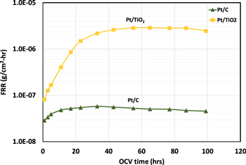
Figure 2. Impact of cathode catalyst support types on membrane chemical degradation rate. Pt/C or Pt/TiO2 used as cathode catalyst. OCV test conducted at 110 °C, 25% RH. H2/air (An/Ca) flow: 265/630 sccm; An/Ca pressure: 150 kPa. Pt loading, 0.05 mgPt cm−2; TiO2 loading, 19 μgTiOx cm−2.
Download figure:
Standard image High-resolution imageIt is seen in Fig. 2 that the FRR is over 50x higher (compared at ∼60 h of OCV run time) for MEA with Pt/TiO2 electrocatalyst as compared to that with Pt/C electrocatalyst. Clearly, the presence of Pt/TiO2 electrocatalyst has significantly increased the rate of membrane chemical degradation. The FRR, i.e., membrane chemical degradation rate, increases with run time in the first 20 to 40 h. Similar observation has been documented in OCV test of PFSA membrane, 16,20 Among the two possible pathways of membrane degradation reactions, i.e., (1) unzipping of polymer chain from end group (2) chain scission (cutting) of the polymer backbone, which creates two fresh end groups for the unzipping pathway. It is believed that chain scission mechanism is responsible for the initial acceleration in degradation rate due to the creation of more reaction sites for membrane degradation reactions. 16,20
Impact of TiOx on the rate of membrane degradation
The significant increase in membrane degradation rate with Pt/TiO2 as electrocatalyst is most likely due to the TiO2 support. To quantify the effect of TiO2 on membrane degradation, three different quantities of TiO2 was added to the electrode ink with Pt/C as electrocatalyst. The TiO2 loading levels were set at 0.33 μgTiO2 cm−2 (denoted as 1x), 1.32 μgTiO2 cm−2 (denoted as 4x), 5.28 μgTiO2 cm−2 (denoted as 16x). Figures 3a and 3b shows the FRR measured during the 100 h of OCV run time for various levels of TiO2 in either anode or cathode, respectively. FRR for the same electrode without any TiO2 addition is also plotted in the figure for comparison. It becomes apparent that by adding the TiO2 support material alone at a loading as low as 0.33 μgTiO2 cm−2 can trigger 5x increase in fluoride release rate (Fig. 3a, No TiO2 vs 1x TiO2 at around 60 h). Furthermore, the membrane degradation rate increases with the loading of TiO2, irrespective of being in anode or cathode. This confirms that the impact induced by Pt/TiO2 is indeed caused by TiO2 support.
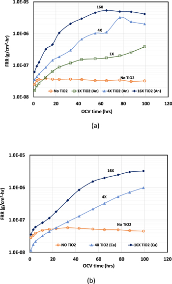
Figure 3. Impact of TiO2 support material in (a) anode and (b) cathode on membrane chemical degradation rate. OCV test conducted at 110 °C, 25% RH. H2/air (An/Ca) flow: 265/630 sccm; An/Ca pressure: 150 kPa.
Download figure:
Standard image High-resolution imageAs noted earlier, researchers have shown success in using Magneli phase titanium oxide such as Ti4O7 to improve the electrical conductivity. Typically, a high temperature treatment process (∼1000 °C) is involved to obtain Magneli phase, 5 which inevitably reduces the available surface area for platinum dispersion. To assess if a different format of titanium oxide has similar impact on membrane chemical degradation, Ti4O7 was also added to the electrode at a same 16x loading as TiO2, and the results of the FRR are shown in Fig. 4. It is found that Ti4O7 accelerates the membrane degradation rate in a very similar manner as TiO2. Therefore, process such as a high temperature treatment does not really alter the chemistry of titanium oxide leading to membrane chemical degradation.

Figure 4. Comparison between TiO2 and Ti4O7 on membrane chemical degradation rate where TiO2 or Ti4O7 was added either to the anode or cathode. OCV test conducted at 110 °C, 25% RH. H2/air (An/Ca) flow: 265/630 sccm; An/Ca pressure: 150 kPa.
Download figure:
Standard image High-resolution imageTo quantify the cumulative damage to the membrane after the 100 h of OCV test, the percentage fluorine inventory loss was compared among different TiOx types, loading and locations (anode vs cathode) in Fig. 5. The total measured fluorine release for each case is calculated by integration of the FRR (shown in Figs. 3 and 4) over the OCV run time. The percentage fluorine inventory loss is the total measured fluorine release normalized to the overall fluorine inventory in fresh membrane. It is seen in Fig. 5 that the fluorine inventory loss for MEA without TiOx is only ∼0.25% after 100 h of OCV test. However, the inventory loss is 10 – 100 times higher with trace amount of TiOx in the electrode depending on loading levels. For the same TiOx type and loading levels, the loss is higher by a factor of ∼2–4 when TiOx is in the anode side. However, the difference is rather small for Ti4O7 between being in anode vs in cathode. In the same electrode and at the same loading level, the trend is not consistent between TiO2 and Ti4O7: the loss is higher for TiO2 in anode, but it is lower when it is in the cathode side. Despite the differences, the amount of F loss observed for TiOx containing MEAs is unacceptable for long term durability of PEM fuel cells.

Figure 5. Total F inventory loss of the membrane after 100 h. of OCV test. The solid circle and bar indicate the average value of the two data points represented by the open circle (replicate measurements from two cells).
Download figure:
Standard image High-resolution imageMembrane thickness measurement after OCV test
It is conceivable that the loss of fluoride, particularly at a higher level, will lead to membrane thinning. This is confirmed by the measurement of membrane thickness using SEM after OCV test. A schematic of the cross-section view of the composite PFSA membrane used in this study is shown in Fig. 6a. There is an ePTFE re-enforcing layer sandwiched between two ionomer layers, exhibiting the three-layer structure. Using this re-enforcing layer as marker, the ionomer layer thickness in membrane facing the anode and cathode side can be independently measured. Figures 6b and 6c show examples of the SEM cross-section image of the membrane after the OCV test for MEAs with No TiO2 and MEAs with 16X (5.3 ug cm−2) TiO2. The boundary between the ionomer layer and electrode as well as the ePTFE layer can be clearly identified and the variation in thickness can be quantified. The ionomer layer exposed to the anode side is highlighted by two red dash lines in the figure.
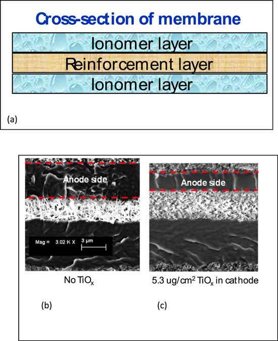
Figure 6. (a) Schematic of the cross-section view of the composite PFSA membrane; and the cross-section SEM image of membrane in MEA after 100 h of OCV test: (b) MEA with NO TiOx added to the electrodes. (c) MEA with 16X (5.3 ug cm−2) TiOx in the cathode. The layer between the two red dash lines define the anode side of the membrane.
Download figure:
Standard image High-resolution imageThe measured ionomer layer thickness using SEM cross-section is shown in Fig. 7. When there is no added TiOx in the MEA, both ionomer layers are measured at ∼4 μm after the OCV test. This thickness is nearly the same as that of a pristine membrane and is consistent with the fact that there is only 0.25% total fluorine inventory loss. As expected, membrane thinning is observed when TiOx is present in either anode or cathode. What is striking though, is that there is over 40% membrane thinning in the anode side of the membrane, including those cases when TiOx is in the cathode side. In contrast, thinning in cathode side of the membrane is largely negligible. This observation could suggest that membrane degradation during the OCV test likely occurs preferentially in the membrane close to the anode side.

Figure 7. Membrane thickness in MEA after 100 h. of OCV test measured by the cross-section SEM. The TiOx loading is 5.3 μgTiOx cm−2 except for Pt/TiO2, which has a 19 μgTiOx cm−2 loading. Note: "membrane (an)" refers to the membrane layer exposing to anode side.
Download figure:
Standard image High-resolution imageSince the exhaust water from anode and cathode was collected separately, the fluoride release rate can be determined from the anode and the cathode side, respectively. The ratio of the FRR between the anode and the cathode is shown is Fig. 8. Other than the case of no TiOx in the electrode which has a ratio close to 1, majority of the cases with TiOx in electrode show a ratio of 2–5, which means a larger fraction of the fluoride generated from membrane degradation emits from the anode side. There is no current nor water production from electrochemical reaction under OCV condition. Since the inlet RH is the same for anode and cathode, the water flux at outlet will be proportional to the respective gas flow rate. Thus, the water flux ratio between anode and cathode should be about 0.4 (270/630 = 0.4). Obviously, the fluoride concentration in anode must be much higher for electrode with TiOx to have higher FRR, which is exactly seen in the fluoride concentration measurement. Higher fluorine concentration local to the anode side is consistent with the observation of predominant anode side membrane thinning/degradation.
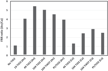
Figure 8. The ratio of fluoride release rate (FRR) between anode emission vs cathode emission at 40 h. of OCV time.
Download figure:
Standard image High-resolution imageClearly, with these dramatic increases in membrane chemical degradation rates even with trace amounts of TiOx, it becomes inviable to employ TiOx in PEM fuel cell electrode as electrocatalyst support, or for any purpose near an MEA, although the superior corrosion-resistance has been proved time and time again compared to carbon.
Titanium migration within the MEA
The redistribution of titanium species through the through-plane direction of the MEA is measured using EPMA line scan that tracks platinum, titanium, as well as sulfur. Figure 9 shows the integrated Ti X-ray counts across the MEA after the OCV test. Figures 9a and 9b shows results of MEAs with TiOx in the anode and the cathode, respectively when the MEA was fabricated. The total Ti X-ray counts are close to zero in MEAs without added TiOx, and shows reasonable linear dependence on initial TiOx loading. Thus, the titanium X-ray count is used as a tool to quantify the through-plane redistribution of Ti species across anode, membrane, and the cathode.

Figure 9. X-ray intensity of Ti species measured by the cross-section EPMA line scans after 100 h. of OCV test: (a) TiOx in the anode (b) TiOx in the cathode.
Download figure:
Standard image High-resolution imageIt is seen in Fig. 9 that although TiOx is either in the anode or cathode at the time of MEA fabrication, titanium species were detected everywhere across the MEA after the OCV test. Certainly, the starting location still retains the highest amount of TiOx among the three portions of the MEA. The percentage distribution of Ti species in the through-plane direction of the MEA is summarized in Table I. When TiOx is in the anode, there is about 55% of the titanium species remains in the anode side. While if TiOx is in the cathode to start with, there is about 81% of the titanium species remains in the cathode.
Table I. Ti species distribution across MEA after OCV test.
| TiOx Location | TiOx Loading (ug cm−2) | Ti species Distribution (%) | ||
|---|---|---|---|---|
| Anode | Membrane | Cathode | ||
| Anode | 1.32 | 59 | 18 | 23 |
| Anode | 5.28 | 51 | 24 | 25 |
| Cathode | 1.32 | 14 | 6 | 80 |
| Cathode | 5.28 | 4 | 13 | 83 |
The migration of titanium is presumably achieved by the diffusion of titanium ionic species driven by concentration gradient, which suggests TiOx dissolution in the acidic environment of the PEM fuel cell electrode. Ex-situ leaching experiment has been conducted to verify if soluble Ti species can be detected in the solution phase in a mixture of TiO2 power and 0.1 N H2SO4 aqueous solution. The mixture was kept at 95 °C for various times and the supernatant was extracted for ICP analysis. The measured Ti concentration is shown in Fig. 10. The result of a blank experiment which does not have TiO2 in the solution was compared with those with 50 or 150 mg of TiO2. Clearly there is soluble Ti species when TiO2 is in contact with acid solution. The concentration of dissolved Ti species increases with leaching time, however, there is not much difference in dissolved Ti species concentration between the two TiO2 solid quantity levels. Nevertheless, the results prove that there is finite amount of dissolution and ionic Ti species formation when TiO2 is in direct contact with 0.1 N H2SO4 solution, which simulates the PEM fuel cell electrode acidic environment.
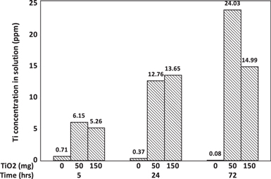
Figure 10. The concentration of Ti species in the supernatant of 0.1 N H2SO4 solution containing TiO2 solids measured by ICP.
Download figure:
Standard image High-resolution imageDiscussion
It has been well established in the literature on the oxidative species that are responsible for the chemical degradation of polymeric membrane used in PEM fuel cell, including hydroxyl radical (•OH), hydroperoxyl radical (•OOH), as well as hydrogen peroxide (H2O2). 13,15,16 Out of the three oxidative species, hydroxyl radical (•OH) is considered as the most aggressive oxidants in the fuel cell environment which can abstract the vulnerable hydrogen atoms in the weak end group of the polymer chain such as –COOH or –CH. 13,15,16
Hydrogen peroxide can be formed at the anode or cathode by direct reaction of crossover hydrogen and oxygen through the membrane (i.e., H2 crossover to cathode and O2 crossover to the anode). 21–23 The reaction between H2O2 with Fe2+ ion can accelerate the generation of hydroxyl radical (•OH): 15,16

The mixture of hydrogen peroxide and ferrous iron is sometimes referred to as "Fenton reagent" and the above reaction (Eq. 2) is called "Fenton reaction."
The detrimental effect of ionic Fe species present in a fuel cell MEA on membrane chemical degradation has been widely recognized and well-studied. 12,15,16 However, the impact of Ti ion on PEM fuel cell membrane durability has rarely been reported. In fact, Fenton reaction realized by Ti3+/Ti4+ through the following reaction path has been documented by Dixon and Norman in 1960s in their electron spin resonance (ESR) studies of alcohol oxidation: 24


Reaction between acidic solutions of titanous ion and hydrogen peroxide was found to generate a singlet in the ESR spectrum, which was attributed to the hydroxyl radical (•OH). The addition of alcohols to the reactants resulted in the creation of signal from organic radicals formed by the abstraction of a hydrogen atom from the C–H bond by the hydroxyl radical (•OH). 24 Separately, in a catalytic synthesis process reported by Drug and Gozin to convert hydrazo compounds into azo derivatives, the proposed mechanisms of the conversion also involve the formation of hydroxy radical (•OH), generated by Ti3+ single-electron reduction of H2O2. 25
In a more recent work in the area of wastewater treatment, Liu et al. reported a comprehensive study on the mechanism of using urchin-like TiO2 nanostructure as catalyst to eliminate organic pollutants. 26 It was experimentally demonstrated that in the presence of both TiO2 and H2O2, methylene blue (MB) (a model pollutant compound) can be degraded through the following reaction pathways:


The presence of Ti3+ as well as •OH (using spin-trapping agent) in the reaction system has been unambiguously demonstrated by ESR spectra. In this heterogeneous reaction system both Ti3+ and Ti4+ ions reside on the TiO2 solid surface and the alternative switching between Ti3+ and Ti4+ driven by H2O2 is considered the critical enabler to this self-sustaining catalytic process. 26
In the present work, PFSA membrane degradation increases dramatically due to TiOx in the electrode (Figs. 2–4).The ex situ leaching test shows finite dissolution of TiOx into ionic Ti species in acidic environment (Fig. 10). It has been reported that when TiO2 film is in contact with acid media, colorless soluble Ti4+ species are formed. 27 Although the nature/valence state of the ionic Ti species were not determined, the EPMA results on MEA after OCV test clearly show the movement of titanium, presumably in ionic form, from one portion (either anode or cathode) to the rest regions of a MEA (Fig. 9). According to Pourbaix diagram, 28 the dissolution of TiO2 into ionic species depends on pH as well as electrode potential: both low pH (acidic) and lower potential (reducing) promotes the dissolution process. The observation that ∼ 81% of the titanium species remaining in the cathode compared to that of ∼55% remaining in the anode side (Table I) could be explained by the effect of potential on TiO2 dissolution, since the anode is close to 0 V (H2 side) while the cathode is over 0.9 V (air/O2 side) during the OCV test.
It is conceivable that once titanium ion forms and diffuses in the membrane and electrodes, it can proceed to generate •OH (•OOH as well) radical through reactions 3 and 7 due to the presence of sufficient H2O2 (10–30 ppm) under OCV condition. 22,23 The hydroxyl radicals (•OH) then attack the polymer chain and end groups causing membrane chemical degradation, manifested by both fluoride emission (Fig. 5) and loss of membrane thickness (Figs. 6–7).
To further establish the correlation between membrane chemical degradation and the dissolved Ti ionic species, the total fluorine inventory loss (shown in Fig. 5) is plotted against the integrated signal for migrated Ti (i.e., Ti in region where TiOx was not placed when MEA was fabricated) in Fig. 11. The linear regression line does not include the triangle data point, which deviates from the rest of data and no obvious reason has been found for this deviation at this point. In general, the fluorine inventory loss shows very strong dependence on the migrated Ti species, presumably Ti ions such as Ti3+ and/or Ti4+ dissolved from the TiOx particles. This trend further corroborates the mechanism proposed above suggesting Ti ions are responsible for the increased membrane chemical degradation through the "Fenton reaction" depicted in Eq. 3.

Figure 11. The total F inventory loss of a MEA vs the integrated X-ray counts of migrated Ti species (measured by EPMA) after the OCV test. Note: the linear regression line does not include the triangle data point.
Download figure:
Standard image High-resolution image
The results in Figs. 7 and 8 suggest that there is a preferential degradation in anode side of the membrane, i.e., majority of fluoride emission and membrane thickness reduction come from the anode side. Two explanations could be plausible according to Eq. 3: (i) Higher H2O2 concentration has been measured in the anode during the OCV test, 22,23 which increases the rate of reaction 3 to generate hydroxy radical (•OH). Meanwhile higher H2O2 concentration can also increase the rate of Ti4+ reduction to Ti3+ through reaction 7. (ii) Anode side may provide additional reaction pathway for Ti4+ reduction through:

Due to the abundance of hydrogen in the anode and the adsorbed H atom on Pt, Ti4+ in the vicinity of Pt particles can be reduced by the adsorbed H atom to Ti3+. This additional reaction path can increase the frequency of Ti3+ regeneration and thus accelerate reaction 3 that promotes •OH production. Ti4+ reduction by a •H has been proposed in the reaction cycle reported by Drug and Gozin. 25 Certainly, additional work is needed to verify if either or both proposed explanations are in play.
Conclusions
Pt/TiO2 as electrocatalyst was found to significantly increase the chemical degradation rate of the PFSA membrane. The increased degradation was determined to be due to TiOx (TiO2 or Ti4O7), which is widely recognized as promising corrosion-resistant electrocatalyst support. The fluorine inventory loss is almost 100 times higher at 5.3 ug cm−2 TiOx loading compared to that without added TiOx. The membrane appears to be degraded preferentially in the anode side, irrespective of which electrode the TiOx is in before the OCV test. Migrated Ti species as a result of TiOx dissolution in an acidic environment have been quantified by EPMA in the MEA and Ti dissolution was confirmed by ICP in ex situ leaching test of TiO2 powder.
The membrane chemical degradation induced by TiOx is proposed to be due to dissolved ionic Ti species, likely Ti4+ and/or Ti3+, reacting with H2O2 through a Fenton reaction and generating hydroxyl radicals (•OH) that decompose the membrane. This proposed mechanism is supported by the strong dependence of fluorine inventory loss of the membrane on the quantity of migrated Ti species. The regeneration of Ti3+ from Ti4+ is postulated to be through oxidation of H2O2 and/or the H atom adsorbed on Pt.
Several questions of fundamental interest remain to be answered, e.g., direct verification of the Ti3+/Ti4+ redox pair in situ in fuel cell and determining the exact reaction(s) for Ti4+ reduction, particularly in the anode. Irrespective of the precise mechanisms of Ti3+/Ti4+ redox cycling, TiOx is clearly not a viable electrocatalyst support for PEM fuel cells. Research efforts should be re-directed toward alternative oxides with similar corrosion-resistance.
Acknowledgments
This work was partially supported by U.S. Department of Energy, Office of Energy Efficiency and Renewable Energy under grant DE-EE0007651. The authors would like to thank Kyle Fillo and Jean Dias for their assistance in IC and ICP analysis, Cristin Keary for conducting SEM measurement, Ratandeep Kukreja for his support in EPMA analysis, Kathryn Stevick and David Lindsey for the engineering support.