
Abstract
Solid state electrolytes are receiving significant interest due to the prospect of improved safety, however, addressing the incidence and consequence of internal short circuits remains an important issue. Herein, a battery based on a LiI-LiI(HPN)2 solid state electrolyte demonstrated self-healing after internal shorting where the cells recovered and continued to cycle effectively. The functional rechargeable electrochemistry of the self-forming Li/I2-based battery was investigated through interfacial modification by inclusion of Li metal (at the negative interface), and/or fabricated carbon nanotube substrates at the positive interface. A cell design with lithium metal at the negative and a carbon substrate at the positive interface produced Coulombic efficiencies > 90% over 60 cycles. Finally, the beneficial effects of moderately elevated temperature were established where a 10 °C temperature increase led to ∼5× lower resistance.
Export citation and abstract BibTeX RIS
Solid state electrolytes are receiving significant interest over the past several years as they provide a promising alternative to liquid electrolytes, which can be flammable, toxic, or lead to capacity loss by enabling undesired dissolution of electroactive species. Some solid-state electrolytes can also perform the role of the separator within the cell, negating the need for an additional cell component. 1 Further, solid state electrolytes also offer the promise of using lithium metal as a negative electrode providing a theoretical specific capacity of 3860 mAh g−1, 2,3 higher than graphite anodes (372 mAh g−1) 4 or even conversion anodes such as Si (3590 mAh g−1 based on Li15Si4). 4,5
Despite progress in advancing ionic conductivity, the adoption of solid electrolytes is still inhibited by their propensity to form dendrites leading to catastrophic internal short circuits. 6,7 Formation of dendrites may also lead to irreversible lithium loss during cycling as a result of both chemical and physical instability 8 as the growth of a dendrite exposes fresh, unpassivated lithium surfaces, encouraging undesirable chemical side reactions with other components of the battery, such as the electrolyte itself. Furthermore, a dendrite can break from its base to cause a physical isolation from its electrical connection to the current collector to produce "orphaned" or "dead" Li that, though metallic, can no longer contribute to the capacity of the cell. 8 The morphology of dendritic lithium deposits has been shown to relate to the applied current density, where testing at a higher current density leads to the promotion of dendrites, and lower current densities may lead instead to mossy deposits of Li0. 9 The formation of dendrites has been observed both with both oxide type electrolytes such as Li7La3Zr2O12 (LLZO), and sulfur based electrolytes such as Li2S-P2S5. 10 Detailed simulations of the potential profiles within solid state batteries have proven important in driving the field forward. 11 The critical current density (CCD) has been used to describe the current maximum sustainable current density without short circuiting as a function of temperature. 12–17 The CCD of liquid electrolytes is in the milliampere cm−2 range, 18,19 while in comparison, solid state electrolytes show significantly lower CCD, typically in the microampere cm−2 range 20 even after surface modification, 21–26 metal substitution, 27–29 and the incorporation of additives. 30–34 Thus, it has been suggested that solid state electrolytes are in actuality more prone to dendrites and accompanying shorts compared to traditional liquid electrolyte based batteries. 10 Therefore, addressing the consequence of short circuits due to lithium dendrite formation is a critical issue to be resolved for solid-state electrolyte batteries.
Rechargeable batteries based on the Li/I2 couple have received attention due to the potential for high energy density (>500 Wh kg−1 and 1000 Wh l−1). 35 Primary Li/I2 batteries have been successfully deployed commercially as the battery of choice for implantable pacemakers with an outstanding record of safety and reliability. 35–37 Reports on commercialized primary cells include cells with a Li metal anode and a cathode composed of lithium iodine and poly-2-vinylpyridine (P2VP) in a ratio of either 30:1 or 50:1 (LiI:P2VP). 37,38 The characteristic of the Li/I2 primary battery is the formation of an LiI layer with discharge that increases in thickness and is accompanied by increased cell impedance as the reaction progresses. 39
A limited number of reports have extended studies of the Li/I2 solid electrolyte system to rechargeable batteries. 40 Self-formation of a Li/I2 based cell including lithium iodide hydrate with polyvinyl-pyrrolidone additive demonstrated rechargeability yet showing higher impedance over time has been reported. 41 Other reports considered the use of alloying current collectors, 42 inclusion of an interdigitated cell design, 43 and the inclusion of LiI(3-hydroxypropionitrile)2 on the surface of a lithium metal anode. 44 Recently, electrochemical formation of cells using LiI-LiI(HPN)2 electrolyte was demonstrated as confirmed by X-ray diffraction and a stable open circuit voltage. 45 Subsequent studies showed the role of the current collectors on the impedance of the cell to be significant. 46 Simulations have also highlighted the importance of maintaining physical contact between the solid electrolyte and the electrodes. 47
Herein, we report solid-state Li/I2 based cells that demonstrate the ability to self-heal after a short circuit and provide the opportunity for high Coulombic efficiency on cycling. Several cell designs including modifications of the parent solid electrolyte thickness and the negative and positive interfaces through inclusion of lithium metal and/or carbon nanotube substrates were explored and evaluated through electrochemical impedance spectroscopy (EIS) as well as charge/discharge cycling. The role of lithium iodide hydrate relative to Coulombic efficiency over multiple charge-discharge cycles was explored. Further, the beneficial effects of moderately elevated temperature on this system were established.
Experimental
LiI(HPN)2 (LiI(C3H5NO)2) was prepared following a previously reported synthetic protocol, wherein LiI and 3-hydroxypropionitrile (HPN) were combined at a molar ratio 1:2. 48 Synthesized LiI(HPN)2 was combined with LiI at 80% LiI/20% LiI(HPN)2 by weight. Coin type cells were constructed using 80% LiI /20% LiI(HPN)2 (by mass) to generate composite solid state electrolyte with a thickness of ∼0.5 mm (areal capacity 5.25 mAh cm−2). Cell modifications included investigation of different parent solid electrolyte thicknesses (0.3, 0.5, 0.9 mm), addition of a thin lithium metal foil, 0.2 mm, on the negative electrode side and/or a multiwall carbon nanotube (CNT) substrate, 0.1 mm, at the positive electrode interface. The cell configurations with no added lithium (I and III) are balanced cells. The cells with added lithium (II and IV) are cathode limited.
All cell assembly was performed within an argon filled inert atmosphere glove box. Materials handling was in a glove box or dry room held at −40 °C dew point. XRD patterns for LiI starting reagents were collected using a Rigaku Miniflex X-ray diffractometer with Cu K α radiation and Bragg-Brentano geometry. Rietveld refinement was conducted for the XRD patterns using GSASII for analysis.
49
For the refinements of LiI to determine relative composition of LiI and LiI·H2O, crystallographic files corresponding to either the LiI rocksalt phase
50
or lithium hydrate monohydrate, (LiI·H2O)
51
were utilized to refine the unit cell, phase fraction, microstrain, crystallite size, Uiso and March-Dollase MD ratio. The peak ratio was determined from peak intensity after background subtraction, where the major peak corresponding to the LiI phase was chosen at ∼26°  while the peak intensity for the hydrated LiI phase, LiI·H2O, was ∼20° 2
 Peak ratios between the LiI and the LiI•H2O phases were used to determine the relative ratio, and subsequent percentage of each phase.
Electrochemical Impedance Spectroscopy (EIS) was obtained in a frequency range of 1 MHz to 1 Hz and galvanostatic cycling was performed using a BioLogic VSP. Electrochemical testing of the cells was conducted using current densities of either 5 μA cm−2 or 10 μA cm−2. A lower voltage limit of 5 mV or capacity equal to charge was designated as full discharge. The frequency of shorting per cycle was analysed and compared between the different coin type cell configurations using Microsoft Excel Statistical Package T-test assuming unequal variance with an alpha value of 0.05. Efficiency was calculated as (discharge capacity for cycle n)/(charge capacity for cycle n).
Backscattering scanning electron microscopy (SEM) images and energy dispersive spectroscopy (EDS) mapping of the electrodes were collected with an analytical high-resolution SEM (JEOL 7600 F) instrument. SEM images were acquired at an accelerating voltage of 5 kV while the EDS mapping data were obtained at 20 kV. To prevent sample degradation from the ambient environment, the cycled electrodes were recovered inside the argon-filled glovebox and transferred to the microscope under an inert atmosphere.
Results and Discussion
Cells constructed using the solid electrolyte 80LiI-20LiI(HPN)2 were activated upon charge where lithium metal is formed as the negative interface and iodine forms at the positive interface in situ (Fig. 1A). Successful charge of the cell provides a stable open circuit potential ∼2.8 V consistent with previous reports. 52 A schematic of self-healing property upon dendrite formation for the Li/I2 cell is shown in Fig. 1B. In this study, four cell designs were probed with the inclusion of Li metal and/or CNT at the negative or positive interfaces, respectively. Fig. 1C, identifies I the solid state electrolyte alone, II with Li metal on the negative interface, III with a CNT substrate on the positive side, and IV Li metal on the negative side and a CNT substrate on the positive. The motivation for the modified cell designs is based on the addition of excess lithium to compensate for losses due to dendritic growth and isolation due to lithium orphaning as well as other parasitic losses. The CNT substrate was added to provide enhanced electrical contact of the solid electrolyte with the stainless-steel substrate and to adsorb I2 as it forms electrolytically upon charge.

Figure 1. Schematic of (A) self-forming solid electrolyte upon charge, (B) self-healing upon dendrite formation, and (C) Cell designs I solid electrolyte only, II including lithium, III including CNT substrate, and IV including both lithium and CNT substrate.
Download figure:
Standard image High-resolution imageEach of the cell designs containing solid electrolyte of thickness (0.5 mm) was tested by galvanostatic charge-discharge cycling under a current density of 10 μA cm−2 where the cells were discharged to a voltage limit of 0.005 V, Fig. 2. The voltage profiles of the initial ten cycles of each configuration are shown in Fig. 2A. A significant observation from consideration of the data is that even after evidence of internal short circuits as noted in Fig. 2A, cell designs III and IV the cells recover fully and regain the ability to effectively cycle. Since LiI is generated upon discharge, once the lithium dendrite contacts the iodine additional LiI is formed to heal the short circuit and allow the cell to regain function.

Figure 2. Cell designs I (blue), II (red), III (yellow) and IV voltage profiles for (A) first 10 cycles, and (B) first cycle discharge. (C) Coulombic efficiencies over sixty cycles for each cell design. Cell impedance (D) prior to charging, and (E) after 60 (dis)charge cycles in the discharged state, insets showing equivalent circuits.
Download figure:
Standard image High-resolution imageDesigns I and II displayed smooth voltage profiles with no evidence of internal shorting during the test. The delivered capacity of each cell increased with each subsequent cycle demonstrating increased utilization of the active materials lithium and iodine. In contrast, designs III and IV evinced shorting with voltage fluctuations apparent as early as the third cycle, followed by effective self-healing.
The capacity of the cell types III and IV was more stable over the 10 cycles and these cells did not demonstrate an increase in capacity with cycle number as was observed in cell types I and II. Figure 2B depicts the first discharge cycle voltage profiles of each of the cell designs. Design IV containing both the lithium and CNT interfaces shows the highest loaded voltage as well as clear evidence of a discharge plateau compared to sloping voltage profiles for the other three cell designs.
Electrochemical impedance spectra were recorded for each cell design in the as prepared state and in the discharged state after 60 cycles. Impedance measurements on the as assembled cells were fit using the equivalent circuit shown in the Fig. 2D inset. The R2 values for cell designs I, II, III and IV were 410, 190, 150 and 150 kΩ, respectively, where the cell design with no interface modifications showed the highest value. After 60 cycles, the impedance shows the influence of two interfaces with the presence of two semi-circles in the Nyquist plots, Fig. 2E. The (R1 + R2) values of 138, 70, 133 and 117 of kΩ for cell designs I, II, III and IV, respectively, are lower than prior to activation. Interestingly, cell design II with the lithium modified interface shows the lowest impedance after cycling even though it does not demonstrate the highest efficiency.
The Coulombic efficiency for each of the cell designs over 60 (dis)charge cycles is shown in Fig. 2C. Cell designs I and II display low efficiency over the first several cycles and improve to ∼60% over the course of the first ten cycles consistent with the capacity increase depicted in Fig. 2A. Cell design III showed an initial moderate increase in efficiency and reached an efficiency value of ∼45%. Most notable is cell design IV that consistently displayed >90% Coulombic efficiency. Notably, cell design I with stainless steel negative and positive interfaces contacting the solid state electrolyte displays significant variation in Coulombic efficiency compared to the other cell types indicating that the formation of the negative and positive electrodes on stainless steel is less consistent and less efficient than the modified interfaces using lithium metal on the negative and CNT on the positive. The results on stainless steel surfaces agree with a prior report investigating the effect of interfacial effects in the LiI solid state cell system. 46 Overall, higher efficiencies were exhibited by the lithium-containing designs, i.e., II and IV, supporting the hypothesis that the presence of excess lithium may compensate for losses due to dendrite formation or other lithium consuming parasitic reactions.
To probe the incorporation of CNT substrates, pristine electrode cross-sections were characterized using backscatter SEM imaging, Fig. 3. A CNT substrate measuring ∼70 μm in thickness (Fig. 3A) was observed on top of the solid electrolyte layer. A magnified view in Fig. 3B displays that portion of the CNT substrate was indeed embedded into the solid-electrolyte, which was further confirmed by the elemental mapping (Fig. 3C) of the region shown in Fig. 3A. Specifically, the CNT substrate penetrated 50 μm down through the LiI/LiI(HPN)2 layer. The partial integration of the CNT substrate into the LiI-LiI(HPN)2 layer may promote a reduction in path length between the negative and positive interfaces, which could be a contributing factor to the more frequent shorting that is observed in the cells containing CNT substrates (III and IV).
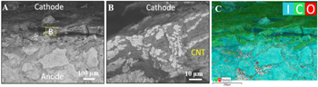
Figure 3. Backscatter SEM images (A), magnified view of corresponding insets (B), and EDS mapping of region A (C) for the cross-section views of pristine cell design III.
Download figure:
Standard image High-resolution image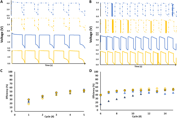
Figure 4. Cell designs I (blue) and III (yellow) voltage profiles with thin (dashed lines) and standard (solid lines) electrode thicknesses at (A) 5 μA cm−2 and (B) 10 μA cm−2. Coulombic efficiencies for cell designs I (blue) and III (yellow) voltage profiles with thin (hollow) and standard (solid) electrode thicknesses at (C) 5 μA cm−2 and (D) 10 μA cm−2.
Download figure:
Standard image High-resolution imageTo further investigate the impact of the electrolyte thickness on shorting propensity, cells of designs I and III were prepared using thin (0.3 mm) and standard (0.5 mm) solid electrodes to determine the effect of the electrolyte thickness on the propensity of the cell to short. The cells were first cycled at a lower (5.0 μA cm−2) current density and then at a higher current density (10.0 μA cm−2). Cell types incorporating a thicker electrode (0.9 mm) were also prepared; however, even at currents as low as 2.5 μA cm−2, the cells could not charge significantly due to overpotential resulting from high resistance and were therefore not tested further. Depicted in Fig. 4, none of the thin and standard thickness cells showed shorting events at the lower current density. Upon increasing to the higher current density, shorting events were observed for some cells. To assess whether a statistical difference was present in the number of shorts per cycle between the various cell types at the differing densities a T-test assuming unequal variances at α = 0.05 was conducted. At 5.0 μA cm−2, no significant differences in shorting event prevalence were observed. At 10.0 μA cm−2, a significant difference was evinced between the thinner and standard electrode thicknesses in cell design III, where the thinner electrode showed a greater propensity for a shorting events.
The influence of elevated temperature was probed via galvanostatic charge-discharge cycling under a current density of 10 μA cm−2, where standard electrolyte thickness (0.5 mm) cells were discharged to a voltage limit of 0.005 V; 40 °C was selected for the investigation as our prior investigations of LiI-LiI(HPN)2 noted softening of the solid state electrolyte above 45 °C. 52 The voltage profiles of the initial ten cycles of each configuration are shown in Fig. 5A with no evidence of internal short circuits. The Coulombic efficiency over 60 cycles at 40 °C is shown in Fig. 5C. The lithium metal containing configurations II and IV show consistently high Coulombic efficiency, >95%. Cell configurations I and III, without the inclusion of additional lithium, show much lower Coulombic efficiency of ∼40% that decreases further over successive cycling consistent with enhanced lithium consuming parasitic reactions at the elevated temperature. Figure 5 depicts the impedance measurements of the cells at 40°C after three charge/discharge cycles in the charged (Fig. 5D), and in the discharged condition (Fig. 5E). At 40 °C, a significant decrease in the magnitude of the impedance was observed in all configurations compared to the values at 30 °C consistent with prior reports of the temperature response of the LiI-LiI(HPN)2 electrolyte. 46,52 In the charged condition, cell designs I, II, III and IV showed R2 values of 28, 32, 34 and 39 kΩ, respectively. In the discharged condition, the impedance values for R1 + R2 were 30, 32, 37, and 41 kΩ for cell designs I, II, III and IV, respectively. In general, an increase in temperature by ten degrees produced an approximate fivefold decrease in impedance.
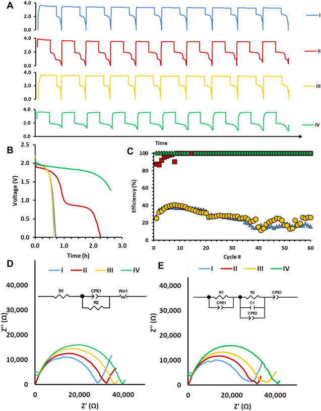
Figure 5. Cell designs I (blue), II (red), III (yellow) and IV (green) evaluated at 40 °C voltage profiles for (A) first 10 cycles, and (B) first cycle discharge. (C) Coulombic efficiencies over sixty cycles for each cell design. Cell impedance (D) prior to charging, and (E) after 60 (dis)charge cycles in the discharged state for insets showing equivalent circuits.
Download figure:
Standard image High-resolution imageFor configurations I and III, the composite electrolyte exists as the only source of Li metal (generated upon charge), and, thus, any lithium consuming parasitic losses would result in subsequent losses in Coulombic efficiency. In contrast, within cell designs II and IV, the additional Li included in the construction acts a reservoir of excess Li to supplant losses due to the parasitic reactions. In general, at elevated temperatures evidence of shorting is infrequent, attributed to the decreased solid electrolyte resistance at elevated temperature.
Along with the loss of lithium due to dendrite formation, the presence of trace H2O within the composite solid electrolyte may promote the formation of LiOH at the negative electrode resulting in the initial production of LiH and Li2O with eventual formation of H2. 42 To investigate this effect, two differing compositions of LiI and LiI·H2O in the 80LiI-20LiI(HPN)2 electrolyte were prepared, with higher and lower hydrate content. Rietveld refinement of XRD patterns (Figs. S1, S2 (available online at stacks.iop.org/JES/168/010519/mmedia)), was used to quantify the hydrate content, Tables S1, S2, showing Composition A to comprise 88.8% LiI and 11.2% LiI·H2O, and Composition B to comprise 95% LiI and 5% LiI·H2O.
Two cell designs, without (type I) and with (type II) lithium metal, were constructed with electrolytes of each composition ("A" or "B") and tested by galvanostatic charge-discharge cycling under a current density of 5 μA cm−2 where the cells were discharged to a voltage limit of 0.005 V. Efficiency comparisons of the differing compositions with the same cell type (I: Fig. 6A; II: Fig. 6B) are provided. The Coulombic efficiency of cells using design type I (SSE only) with higher amounts of LiI·H2O (Composition A) evince lower initial efficiencies with decreased capacity upon the first discharge compared to Composition B. Upon additional cycling, the efficiencies of Composition A cells using designs I and II improve to overtake the Composition B cells with identical designs up to ∼10 cycles. However, further cycling promotes a gradual decrease to mirror the efficiency of cells constructed using Composition B. After 25 cycles, there is minimum impact on efficiency based on the amount of LiI·H2O present in the solid-state electrolyte for both types (Figs. 6A, 6B).
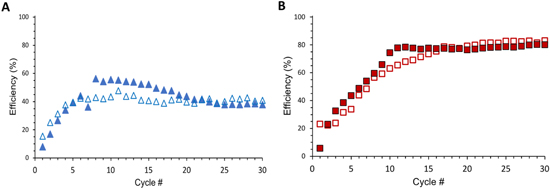
Figure 6. Efficiencies versus cycle number for each Cell design (types I (blue), II (red) and composition (Composition A: filled markers; Composition B: hollow markers).
Download figure:
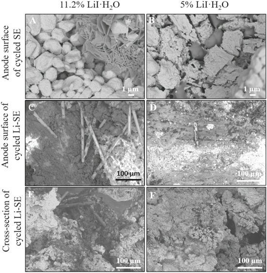
Standard image High-resolution imageThe morphologies of these electrodes were characterized via backscatter SEM imaging, Fig. 7. A generally consistent appearance was observed for all electrodes, regardless of water content or composition, with granular particles of LiI (white) and more flake-like particles of LiI(HPN)2 (grey). In addition, the anode surface and cross-section of cycled II with Composition A 11.2% LiI·H2O (Figs. 7C and 7E) indicated a greater presence of LiOH rods (Figs. 7C and 7E) would be expected to form in the presence of a higher amount of LiI·H2O. Thus, a greater degree of hydration in the LiI resulted in minor yet noticeable alterations to the composite heterostructure, which would not be anticipated to significantly impact the resulting electrochemistry.
Figure 7. Backscatter SEM images for the cycled I in charged state (A)-(B) and cycled II (C)–(F) in charged state with different amount of LiI·H2O. (A)-(B) the anode surface of cycled I with 11.2% LiI·H2O (A) and 5% LiI·H2O (B), bright area for LiI and grey area for LiI (HPN)2. (C)-(D) the anode surface of cycled II with 11.2% LiI·H2O (C) and 5% LiI·H2O (D), bright area for LiI and dark area for LiOH. (E)-(F) the cross-section of cycled II with 11.2% LiI·H2O (E) and 5% LiI·H2O (F), bright area for LiI and dark area for LiOH.
Download figure:
Standard image High-resolution image
Conclusions
Herein is described the ability to impact the functional electrochemistry of a solid-state electrolyte cell through interfacial modification of a self-forming Li/I2 battery based on a LiI-LiI(HPN)2 electrolyte. Notably, this cell design demonstrated self-healing in the form of continued cycling after internal shorting events where the cells recovered and continued to cycle effectively. The addition of lithium metal at the negative interface in combination with a CNT mat at the positive interface produced Coulombic efficiencies > 90% over 60 cycles. In the cell designs where the solid-state electrolyte was the only source of Li, cycling efficiencies were lower likely due to lithium consuming parasitic losses such as orphaned dendrites or chemical reactions. Thus, the presence of an external source of lithium metal proved important in achieving and maintaining high Coulombic efficiency. Finally, the beneficial effects of moderately elevated temperature on this system were established demonstrating a ten degree increase in temperature led to an approximately five times lower resistance and decreased incidence of internal shorts while cycling.
Acknowledgments
This work was supported by the U.S. Department of Energy Office of Energy Efficiency and Renewable Energy under the Advanced Battery Materials Research program, award DE-EE0007785. Microscopic characterization to determine mechanism was supported by the Center for Mesoscale Transport Properties, as part of the Center for Mesoscale Transport Properties, an Energy Frontier Research Center supported by the U.S. Department of Energy, Office of Science, Basic Energy Sciences via grant #DE-SC0012673. Additionally, this research used resources of the Center for Functional Nanomaterials, which is a U.S. DOE Office of Science Facility, at Brookhaven National Laboratory under Contract No. DE-SC0012704. C.S. acknowledges support from the NIH Institutional Research and Academic Career Development Award and New York Consortium for the Advancement of Postdoctoral Scholars (IRACDA-NYCAPS), award K12-GM102778. A.A. acknowledges support from the Graduate Assistance in Areas of National Need Fellowship. E. S. T. acknowledges the support of the William and Jane Knapp Chair of Energy and the Environment.