

Abstract
A novel poly(acrylamide-co-acrylic acid) (P(AM-co-AA)) coating layer is facilely introduced on the top of sulfur composite cathode. The polymer membrane owns abundant and well-distributed microporous framework, favoring large electrolyte uptake and high ionic conductivity. Upon activation with the liquid electrolyte, the porous matrix immediately swells, forming a gel polymer electrolyte coating (GPEC) cathode. Not only does the unique coating design greatly restrain the out-diffusion of polysulfides from the cathode, but also improves ion transport at the cathode/electrolyte interface and provides flexible surface protection for the electrode structure. The GPEC cathode exhibits relatively low polarization, high sulfur utilization and superior cycle stability, as compared to the conventional sulfur cathode.
Export citation and abstract BibTeX RIS
In the booming field of electric vehicles and consumer electronics, developing advanced energy storage systems with high energy/power densities is extremely urgent.1–6 Lithium-sulfur (Li-S) battery has been widely concerned and regarded as one of the most promising next-generation rechargeable battery owing to its high theoretical energy density of 2600 Wh kg−1, abundant sulfur resource and good environmental benefit.7–9 However, the extensive application of Li-S battery has been greatly beset with challenges including insulating nature of elemental sulfur and low-order product lithium sulfide, considerable volume change and undesired shuttle caused by the dissolved polysulfides, resulting in low utilization of active material, severe self-discharge and poor cycle stability.
Nowadays, varieties of strategies have been attempted to address the preceding problems, including sulfur/conductive carbon composite construction, electrolyte composition optimization and cell configuration design.10–12 In particular, the introduction of a coating structure on the top of sulfur cathode has been widely reported13–15 because it is capable of effectively confining the sulfur species within the electrode and maintaining the electrode structure stability as well. It should be prudent in material selection and porous structure control for traditional coating, or it could be counterproductive. For instance, too dense/thick coatings usually impede the penetration of the electrolyte, increase the ion transport resistance, and influence the electrode reaction progress. In addition, if the coating cannot adapt to the electrode volume deformation during cycling, it may be broken or fall off from the electrode and then lose its protective function. These issues mentioned above make the cathode coating technology still needs to be further meliorated and developed.
Gel polymer electrolyte (GPE),16,17 combining the advantages of liquid electrolyte and solid electrolyte, not only has good ionic conductivity and interface compatibility with both electrodes, but also can hold polysulfides in the polymer matrix, hence restraining the redox shuttle. Most of reported GPE were made into an independent membrane unit and placed between the cathode and anode. If the GPE could be introduced on the surface of the cathode as a coating, it is expected to facilitate electrolyte contact with the cathode and better regulate the volume change of the cathode, then avoiding the intrinsic defects of traditional coating cathode and GPE techniques. Up to now, researches on GPE coating cathode have been rarely reported.
Herein, we firstly attempted to introduce the copolymer poly(acrylamide-co-acrylic acid) (P(AM-co-AA)) as a coating on the sulfur cathode. The material can rapidly gelate in organic electrolyte, and the formed porous gel polymer electrolyte coating (GPEC) is closely adhered to the electrode surface, improving ion transport at the interface. More importantly, the gel electrolyte network can reserve a large amount of polysulfides within the cathode and hence minimize Li corrosion and repeated shuttle. The results show that the GPEC cathode exhibits lower electrochemical polarization, higher utilization of active materials, better redox reversibility and cycle stability.
Experimental
Electrode fabrication
70 wt% elemental sulfur (Aladdin, 99.5%) and 30 wt% mesoporous carbon (XFANO, CMK-3) were mixed together in an agate mortar, and then transferred into a tube-type furnace at 155 °C for 12 h under argon flow. The sulfur content in the obtained sulfur/carbon composite was calculated to be 69.6% by TG analysis.
To prepare the pristine cathode, the as-prepared composite, carbon black (Super P, Timcal) and poly(vinylidene fluoride) (PVDF, 6020 Solef) in a weight ratio of 8:1:1 were dissolved in NMP solvent. The slurry was then casted on a piece of Al foil by a doctor blade and dried at 55 °C for 12 h in an air-blowing oven. The sulfur loading in the cathode is 1.8 ∼ 2.0 mg cm−2.
To fabricate the GPEC cathode, a milky solution with the solid content of 5 wt% was prepared by dissolving P(AM-co-AA) powder (Aldrich, Mw 520,000, acrylamide ∼80 wt%, dried at least 24 h at ∼60 °C before use) into the mixture of deionized water/NMP (1/1, v/v), and was further cast on the top of the pristine cathode. For convenient investigation on the coating properties, an independent P(AM-co-AA) membrane was separately fabricated by pouring the above polymer solution onto a piece of smooth glass plate and then drying it by vacuum at 45 °C.
Physicochemical characterization
Thermogravimetric Analysis (TGA) was performed to determine the thermal stability of the polymer powder at a heating rate of 10 °C min−1. UV–Visible absorption spectroscopy (Agilent Cary 5000) was acquired for characterizing the adsorbing ability of the polymer toward polysulfides (produced by dissolving S and Li2S at a molar ratio of 5:1 in a DOL/DME solution). Fourier transform infrared (FTIR) spectra of the membrane were recorded on a NICOLET IS5 infrared spectrophotometer in the range of 4000 ∼ 475 cm−1. The morphology characteristics of porous membrane and sulfur cathode were investigated by scanning electron microscopy (Gemini SEM 300), followed by an energy dispersive X-ray spectroscopy (EDX) for element analysis.
The electrolyte uptake (%) was determined using the relation (Wa-Wb)/Wb✕100%, where Wb and Wa denote the weight of the porous membrane before and after absorbing the liquid electrolyte, respectively. The ionic conductivity was measured by electrochemical impedance spectroscopy (EIS) of stainless steel (SS) symmetrical cell with the porous membrane absorbing the electrolyte on a PARSTAT 4000 electrochemical workstation, and calculated by relation d/(Rb✕A), where Rb is the bulk resistance from EIS, d is the membrane thickness and A is the SS area. The potential window of the GPE was investigated by linear sweep voltammetry (LSV) of a SS/Li cell at a scan rate of 5 mV s−1.
Electrochemical measurement
CR2025-type coin cells were assembled in an Ar-filled glove box with the as-prepared GPEC or pristine cathode, a Celgard2400 membrane as the separator and a piece of Li metal as the anode. The electrolyte consisted of 1 M lithium bistrifluoromethanesulfonamide (LiTFSI) and 0.1 M LiNO3 in the solvent mixture of DME and DOL (1:1, v/v). The E/S ratio in the cell was controlled to be 17 ∼ 18 ml g−1.
Galvanostatic charge/discharge test of the cell was performed on a LAND system in the voltage of 1.7 ∼ 2.8 V at different rate conditions. Cyclic voltammetry (CV) was measured on the electrochemical workstation at a scan rate of 0.2 mV s−1. The EIS responses before and after cell cycling were monitored in the frequency range of 1 MHz to 0.01 Hz with the perturbation amplitude of 5 mV.
To investigate the polysulfide entrapment of the as-prepared cathode, a visual bulk cell was assembled in the glove box, consisting of GPEC or pristine cathode and Li metal anode immersed in the LiTFSI-based electrolyte. The cell rested 1 h after assembly and then discharged at ∼0.1 C between 1.5 V and 3 V on the LAND system. The color change of the electrolyte during initial discharge was recorded.
Results and Discussion
The TGA curve of P(AM-co-AA) powder is shown in Fig. 1a. It can be seen that it is thermally stable under 50 °C, and then the moderate weight loss continues resulting from the release of absorbed water. When the temperature reaches 219 °C, the weight loss suddenly accelerates, which is due to the broken molecular chain and significant thermal decomposition of the polymer. Overall, P(AM-co-AA) meets the requirements for Li-S battery application. UV–vis absorption spectra of polysulfides solution containing different polymer particles are shown in Fig. 1b. The absorption peak around 280 ∼ 300 nm is related to different kinds of long-chain polysulfide species in the solutions, which caused by the disproportionation of Sn2−.18–20 The addition of PVDF in the solution slightly reduces the peak intensity. While the peak intensity further descends when the P(AM-co-AA) particle was soaked, indicating that the copolymerized material has better ability to absorb polysulfides compared to PVDF. It should be mainly benefitted from strong binding of amide (–CONH2) and carboxyl (–COOH) groups in the polymer with the Li-S· species.21 The color depth of various solutions can also validate above variation trend (as shown in the inset of Fig. 1b). It is believed that the adsorption ability of P(AM-co-AA) to polysulfides can be further raised if its copolymerized structure (involved with the polar functional groups) is better regulated.

Figure 1. TGA curve of the P(AM-co-AA) powder; (b) UV–vis absorption spectra of polysulfide solution before and after soaking with the polymer particles.
Download figure:
Standard image High-resolution imageIn order to handily investigate the porous characteristic and properties of the coating layer, the P(AM-co-AA) material was separately coated on a piece of smooth glass plate. Figure 2 exhibits SEM images of the as-prepared membrane before and after electrolyte uptake. There are quantities of interconnected micropores uniformly distributed in the pristine membrane. The abundant porous structure increases the surface area of the coating and allows full absorption of the liquid electrolyte. After electrolyte uptake, as shown in Fig. 2c, the polymer film changed from white to transparent, and the pore size enlarges at some extent, mainly due to swelling in the electrolyte (the electrolyte uptake of the membrane is calculated to be ∼335.6%, being comparable with those previously-reported GPE22,23). Even so, the membrane still maintains good mechanical strength and structure integrity. The swelled polymer membrane becomes a typical gel polymer electrolyte in fact and preserves a large amount of electrolyte in the porous matrix. In addition, it is found that the as-prepared independent membrane can be folded and stretched properly without visible crack, which will be advantageous to accommodate the volume variation of the cathode by providing a flexible surface once it is introduced on the top of the cathode.
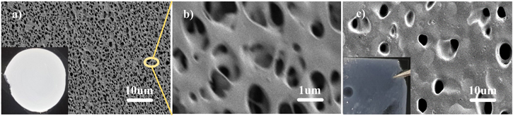
Figure 2. SEM images of P(AM-co-AA) membrane (a), (b) before and (c) after electrolyte uptake.
Download figure:
Standard image High-resolution imageFigure 3a presents the FTIR spectra of the P(AM-co-AA) membrane. For the dried pristine membrane, several characteristic peaks at 1263 cm−1, 1402 cm−1, and 1650 cm−1 can be observed, corresponding to C–O stretching, –CH2 stretching and –C=O stretching, respectively. The absorption peak at around 3187 cm−1 is ascribed as the amino group (–NH2). Much stronger peak at 1297 cm−1 can be assigned to C–N stretching. These characteristic absorptions confirm the chain structure of P(AM-co-AA).15,24,25 Absorbing the electrolyte, the intensities of above peaks obviously enhance, with peak positions shifting slightly. In addition, some new peaks in the range of 500 ∼ 1500 cm−1 appear, possibly due to molecular interaction between the membrane and electrolyte components.22 The LSV test shows that the GPE and LE are electrochemically stable up to 4 V , as shown in Fig. 3b. The stable potential window of the prepared GPE meets the demand of Li-S battery operation. The conductivity of GPE is demonstrated in Fig. 3c. Since ion mobility of GPE strongly depends on the amount of embedded electrolyte in the membrane,26 a room temperature ionic conductivity of up to 1.12 mS cm−1 is reasonable for the P(AM-co-AA)-based GPE, owing to its high electrolyte uptake. Moreover, this prepared GPE possesses high conductivity even at temperatures below 0 °C.
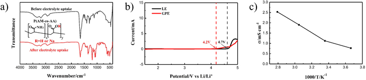
Figure 3. (a) FTIR spectra, (b) LSV measurement and (c) ionic conductivity of the P(AM-co-AA) membrane after electrolyte uptake.
Download figure:
Standard image High-resolution imageFigure 4 illustrates the surface morphologies of pristine cathode and GPEC cathode. As shown in Figs. 4a and 4b, the pristine cathode has a rough and loose surface, with sulfur particles and conductive agents uniformly distributing around the mesoporous carbon or filling in the voids. After introducing the P(AM-co-AA) coating, the electrode morphology is significantly converted to a 3D network formed by the interweaved polymer, increasing porosity of the electrode surface and facilitating adequate penetration of the electrolyte and free ion transport. It should be noted that the apparent morphology of the coating layer on the cathode is different from the previous independent membrane, which should be mainly associated with the change in the surface condition of the substrate. The rough and particle-rich cathode surface may induce the membrane to form fiber-like porous structure. Even so, the easily-gelled and pore-creating essence of the P(AM-co-AA) is confirmed no matter which substrate was employed. Therefore, it is considered that the structural characteristics and properties of the independent membrane still have good guideline value for the coating cathode study.

Figure 4. Surface morphology of fresh sulfur cathode (a), (b) without and (c) with P(AM-co-AA) coating.
Download figure:
Standard image High-resolution imageThe pictures of the visual bulk cell were recorded during initial discharge in order to compare the entrapment ability of the different cathodes toward sulfur species. It can be clearly seen from Fig. 5 that the color of the electrolyte in the pristine cathode case turns light yellow rapidly once the test started and gradually deepens with the increased discharge depth. Even approaching the end of discharge, there are still large amounts of polysulfides retained in the electrolyte, which reveals low utilization of active material caused by intermediate dissolution. In contrast, the bulk cell with GPEC cathode exhibits nearly transparent at the beginning and delivers slight color change during the whole test period. The result is similar to previous reports,27,28 well confirming the efficient polysulfide trapping via the extra gel coating design.
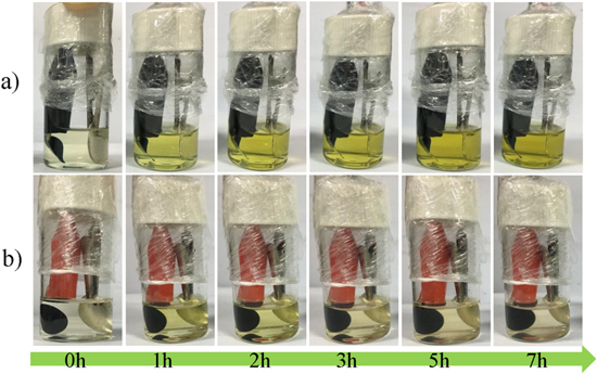
Figure 5. Pictures of the visual cells with (a) pristine cathode and (b) GPEC cathode during initial discharge.
Download figure:
Standard image High-resolution imageCV measurement has been performed to investigate the redox behaviors of Li-S cells. Two reduction peaks located at 2.2 ∼ 2.3 V and 1.9 ∼ 2.0 V can be ascribed to the reduction of sulfur to soluble polysulfides and then further to the insoluble Li2S2/Li2S, respectively.29,30 Two very close oxidation peaks refer to the reverse process. The reduction peaks of GPEC cathode in Fig. 6b emerge at a higher potential and the redox peak difference (0.4 V) is smaller, indicating less polarization and better redox reversibility, compared to that of pristine cathode in Fig. 6a. The discharge plateaus observed in the potential profiles (Figs. 6c and 6d) just correspond to the reduction peaks of the CV curves. It should be noted that the gap (ΔE) of the plateau voltage (identified by the average value in the plateau region) of pristine cathode gradually becomes larger during cycling. In comparison, the ΔE value of GPEC cathode tends to be smaller and then stabilize with the cycles. Obviously, the gel coating improves the redox environment within the electrode, leading to the GPEC electrode more kinetically favorable than pristine electrode.

Figure 6. CV curves of (a) pristine cathode and (b) GPEC cathode; Potential profiles of (c) pristine cathode and (d) GPEC cathode at various cycles.
Download figure:
Standard image High-resolution imageThe cycling performances of two cathodes at different rates are displayed in Figs. 7a and 7b. The pristine electrode delivers a high initial capacity but apparent capacity decays over the repeated cycles. The capacity retention is only 47.5% at 0.2 C and 54.9% at 0.5 C after 100 cycles, respectively. In contrast, the cycle performance of the electrode is significantly improved via introducing the gel coating. The initial capacity of GPEC cathode reaches 1101 mAh g−1 and the reserved capacity is 822 mAh g−1 after 100 cycles at 0.2 C. Even at 0.5 C, the capacity retention still sustains 78.6%. The excellent electrochemical performance is mainly attributed to the factors as follows: (i) The gel coating reserves more sulfur species at the cathode side, effectively preventing polysulfide migration and shuttle; (ii) The ion transport channel and the properties of the cathode/electrolyte interface are improved due to the electrolyte-contained GPE layer closely adhering to the cathode, beneficial to the electrochemical reaction process; (iii) The gel skeleton made of the copolymerized material with good flexibility, can also accommodate the volume deformation of the electrode and enhance the structural stability, even if gelation occurs.
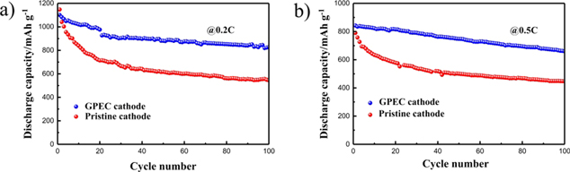
Figure 7. Cyclic performance of various cathodes at (a) 0.2C and (b) 0.5C rate.
Download figure:
Standard image High-resolution imageThe Nyquist plots of pristine cathode and GPEC cathode before and after the charge-discharge cycles are shown in Figs. 8a and 8b, respectively. In general, one semicircle at high frequency and inclined line at low frequency region can be observed. The former stands for the charge transfer resistance Rct31,32 and the latter corresponds to the Warburg resistance (reflecting the diffusion of Li ion and polysulfides in the porous electrode and active material).32,33 The intercept of the semicircle on the real axis is regarded as the ohmic resistance (R0), including the electrolyte and electrode resistance.34 For GPEC cathode, an additional semicircle at lower frequency exists, which could be assigned to the charge transfer process at the GPEC/cathode interface (RGPE).35 The fitted resistance data according to the corresponding equivalent circuit are shown in Table I. It is remarkable that the GPEC cathode have lower overall resistance than pristine cathode no matter before or after the cycles, suggesting that the gel layer improves the interfacial properties due to full electrolyte uptake and close contact with the cathode, and hence provides better transmission path for electron and ions. The EIS analysis well supports the previous results of the GPEC cathode (better rate performance and smaller polarization). Furthermore, each resistance value of GPEC cathode is almost stable during cycling, reflecting high electrochemical stability and good redox kinetics.

Figure 8. Nyquist plots of (a) pristine cathode and (b) GPEC cathode at different cycle stages.
Download figure:
Standard image High-resolution imageTable I. Fitted resistances data from the equivalent circuit.
| Sample | Stage | R0 (Ω) | Rct (Ω) | RGPE (Ω) |
|---|---|---|---|---|
| Pristine cathode | Before cycle | 3.67 | 70.37 | / |
| After 30 cycles | 3.23 | 31.59 | / | |
| After 50 cycles | 2.53 | 31.45 | / | |
| GPEC cathode | Before cycle | 3.17 | 18.48 | 5.23 |
| After 30 cycles | 2.84 | 15.09 | 2.87 | |
| After 50 cycles | 4.56 | 17.09 | 4.57 |
The surface morphologies of two cathodes extracted from the cycled cells were further investigated by SEM. Compared with fresh pristine cathode (Figs. 4a and 4b), a large amount of irregular particles due to the deposition of insoluble sulfides exists after long-term cycling (Fig. 9a). Also, some mesoporous carbon particles expose under magnification (Fig. 9b), implying a certain amount of sulfur species dissolved in the electrolyte without back to the cathode during the charge/discharge process. It inevitably results in active material loss. The GPEC cathode still maintains smooth surface and good porous network (Fig. 9c), compared to that before cycle (Fig. 4c). However, the reticulated fiber thickens to some extent, in consideration of the swelling effect of the polymer coating in the electrolyte, and the effective restraint of the reticular coating towards the S-containing species. The EDS mapping of the cross section of various cathodes after cycling are compared in Figs. 8d and 8e, which further confirm the above conclusions. It can be easily seen that few sulfur species remain after cycling for the pristine cathode, and a large amount of sulfur signals can be collected in the GPEC cathode. The excellent sulfur-immobilization ability of GPEC cathode is supposed to mainly derive from chemical anchoring from the polar functional groups of the polymer. Besides, the boundary of active material layer and gel layer is hardly distinguished in the cross section image of the cycled GPEC cathode, suggesting the compact adhesion of the gel coating on the cathode.

Figure 9. Surface morphologies of (a), (b) pristine cathode and (c) GPEC cathode after cycling; EDX mapping of cross section of (d) pristine cathode and (e) GPEC cathode after cycling.
Download figure:
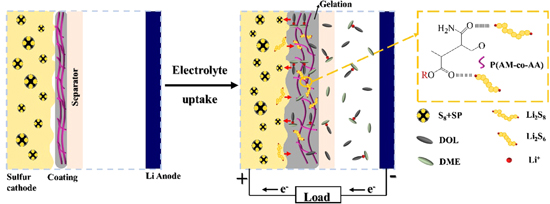
Standard image High-resolution imageHerein, we proposed a schematic diagram for the working mechanism of the novel coating cathode as depicted in Fig. 10. In the novel GPEC construction, most of the sulfur species are well constrained at the cathode side, with the subsequent Li corrosion and repeated shuttle minimized. Owing to the gelation effect, the compactly interfacial contact between the swelled coating and sulfur cathode builds up convenient ion transport path and flexible surface protection for cathode construction. Therefore, the battery performance was notably improved.
Figure 10. Schematic work mechanism of the Li-S battery equipped with GPEC cathode.
Download figure:
Standard image High-resolution image
Conclusions
In conclusion, a protected sulfur cathode with P(AM-co-AA)-based gel coating was proposed for Li-S batteries. The porous coating film can achieve rich electrolyte loading and subsequent rapid gelation. The obtained GPE coating provides strong sulfur-immobilization ability and favorable interface properties, contributing to the overall improvement of electrochemical performances. An initial capacity of 1101 mAh g−1 at first cycle and reserved capacity of 822 mAh g−1 after 100 cycles are exhibited for the GPEC cathode at 0.2 C rate. The novel coated cathode is prone to be prepared at moderate cost, affording a potential route for the industrialization of high-performance Li-S batteries.
Acknowledgments
The work is supported by the National Natural Science Foundation of China (grant no. 51704222 and 51604221).