
Abstract
In this work, aprotic and protic ionic liquid (IL)-based electrolytes designed for calcium-based energy storage systems are investigated. We have shown that these electrolytes display good transport properties and electrochemical stabilities comparable with those of IL-based electrolytes proposed for lithium and sodium-based systems. The use of these electrolytes in electrochemical double layer capacitors (EDLCs) leads to the realization of devices displaying good capacitances paired with a high reversibility and stability. Their use in combination with TiS2 cathode appears more problematic as the cation of the ILs is inserting in the layered structure of this material during the charge process. In this latter case a careful design of the cation appears necessary to guarantee selective insertion of Ca2+ and reversible charge-discharge process.
Export citation and abstract BibTeX RIS

This is an open access article distributed under the terms of the Creative Commons Attribution Non-Commercial No Derivatives 4.0 License (CC BY-NC-ND, http://creativecommons.org/licenses/by-nc-nd/4.0/), which permits non-commercial reuse, distribution, and reproduction in any medium, provided the original work is not changed in any way and is properly cited. For permission for commercial reuse, please email: permissions@ioppublishing.org.
Calcium-based energy storage devices are more and more considered as an attractive alternative to state-of-the-art storage systems such as the lithium-ion battery (LIB). A Ca-ion system relying on an insertion type anode such as graphite would fall short in terms of performance when compared with the state-of-the-art LIBs. However, the use of Ca metal as anode material (1.34 Ah g−1 and 2.06 Ah cm−3) can lead to a leap-frog in energy density in addition of being advantageous in terms of cost and sustainability, Ca being the 5th most abundant elemet on the Earth's crust.1 The development of Ca-based systems, however, is in an early stage and very few, if any, full-cell studies exist,2 by contrast with the more advanced technology based on magnesium (8th most abundant element).3,4 Nevertheless, the lower polarizing character of Ca2+ when compared with Mg2+ holds promise for faster reaction kinetics and hence better power performances for Ca batteries.
One severe obstacle on the road towards calcium-based systems has been the successful deposition and stripping of calcium in inorganic electrolytes. While Mg metal plating can be traced back to the early 1920s, using an electrolyte based on Grignard reagents (R-MgX, X = Br, Cl),5 reversible Ca plating and stripping was demonstrated recently in a carbonate solvent based electrolyte (ethylene carbonate (EC) and propylene carbonate (PC)) at temperatures above 75 °C or at room temperature in ether and glyme based electrolytes.6–9 Although these solvents are relatively cheap and largely used, they are highly flammable and toxic.10 For this reason, the use of safer alternative appears of importance in view of the development of Ca-based systems. Ionic liquids (ILs) have been shown to be a promising alternative in a vast amount of devices, such as batteries, electrochemical capacitors and hybrid, high power devices.11–15 So far, the use of ILs in Ca-based systems has been scarcely investigated.16,17 Nevertheless, considering the favorable properties of ILs, the investigation of their use in Ca-based system appears of importance.
In this work we report about the use of IL-based electrolytes in combination with electrode materials suitable for the realization of Ca-based systems. The ionic liquids 1-butyl-1-methylpyrrolidinum bis(trifluoromethylsulfonyl)imide (Pyr14TFSI) and 1-butylpyrrolidinum bis(trifluoromethylsulfonyl)imide (PyrH4TFSI) have been utilized. Pyr14TFSI is an aprotic IL (AIL), which has been used in a large number of storage systems during the last 10 years. PyrH4TFSI is a protic IL (PIL), which holds a "free" proton on the cation.18–21 This latter category of IL is attracting an increasing interest in the field of batteries, due to distinct interactions of the protic ions within the electrolyte, leading e.g. to an increased lithium-ion mobility compared to AILs.20,22–26 To the best of our knowledge,PILs have never been used for Ca-based systems. Thus, both AIL and PIL have been employed in combination with calcium bis(trifluoromethylsulfonyl)imide (Ca(TFSI)2) to obtain electrolytes suitable for Ca-based systems. In order to achieve a satisfactory solubility of this salt (0.1 mol l−1), 20 mol% of PC have been added in all considered electrolytic solutions. In the first part of the manuscript, the chemical-physical properties of the selected electrolytes have been investigated. Afterwards, their use in combination with activated carbon (AC) has been considered with the aim to verify if these electrolytes can be utilzed for the realization of electrical double layer capacitors (EDLC) and, eventually, of hybrid devices based on Ca chemistry. In the last part of the manuscript the intercalation of calcium ions into layered TiS2 has been addressed, being one of the very few cathode material for which a fully reversible intercalation of Ca2+ was demonstrated.27
Experimental
Preparation of the electrolyte
PyrH4TFSI was synthesized using the same procedure described in Ref. 28. 1-butylpyrrolidin has been used as precursor, LiTFSI for the anion exchange. PyrH4TFSI as well as Pyr14TFSI (obtained from Iolitech) and PC (obtained from Sigma Aldrich, 99.7%) were mixed in a 8:2 molar ratio, respectively. Subsequently Ca(TFSI)2 was added to achieve a molarity of 0.1 mol l−1. Before preperation the water amount in the used liquids has been determined to be below 20 ppm using a C20 Coulometric KF Titrator from Mettler Toledo. The electrolyte was prepared in an MBraun LABmasterpro ECO glove box under argon atmosphere with <1 ppm H2O and <1 ppm O2.
Chemical-physical-characterisation
The conductivity of the electrolyte was measured using a potentiostat ModuLabXM (Solartron analytical) in the temperature range comprised between 30 and 80 °C as described in Ref. 29. The viscosity of the electrolytes was determined using a rheometer MCR 102 (Anton Paar) in the temperature range comprised between 30 and 80 °C as described in Ref. 29.
Electrode preparation
AC-based electrodes were prepared following a procedure identical to that used by Krause et al.30 The dry composition of the electrodes was 90 wt % of active material (AC, DLC Super, Norit) 5 wt % of conducting agent (Super C65, Imerys) and 5 wt % of binder (carboxymethyl cellulose, Dow). The mass loading of the electrodes was comprised between 2.6 mg cm−2 and 3.5 mg cm−2, the electrode area was equal to 1.13 cm2. As (oversized) counter electrodes, AC-based electrodes were used to determine the maximum operative voltage (OPV) of the investigated EDLCs. The electrodes were prepared following the procedure indicated in Ref. 31. The electrode composition was 90 wt % of AC (DLC Super, Norit), 5 wt % of carbon black (Super C65, Imerys) and 5 wt % of binder (polytetrafluoroethylene, Aldrich). The mass loading of these electrodes was about 40 mg cm−2, and their area was 1.33 cm2.
TiS2 (99.995%, Aldrich) electrodes were prepared by tape casting with 10% polyvinylidenfluorid binder and 10% carbon black (Super P, Timcal) as conductive additive, as descibed in Ref. 32. An aluminium foil was used as current collector. 11 mm diameter electrodes were employed with a loading of 0.8 mg cm−2.
Electrochemical measurements
All electrochemical measurements in the EDLC setup have been carried out using a three-electrode Swagelok cell setup. In every cell, Whatman glass microfiber filters (150 mm) were used as separators, drenched with 150 μl electrolyte. The cell assembly was done under argon atmosphere in an MBraun LABmasterpro ECO glove box with <1 ppm H2O and <1 ppm O2. All tests were carried out at 30 °C to ensure that all electrolytes were liquid when employed in the cells.
The electrochemical stability window (ESW) of the electrolytes was measured using a platinum electrode as working electrode, an oversized carbon electrode as counter electrode, and a silver electrode as quasireference electrode (QRE). After a 12-hour open circuit voltage (OCV) measurement to reach equilibrium, the cells were swept from OCV towards either positive or negative direction at 1 mV s−1 until a potential of −6 V vs OCV and 6 V vs OCV was reached, respectively. For each direction, fresh electrolyte was used.
For the determination of the OPV of AC-based electrodes in the investigated electrolyte an AC-based working electrode, an oversized carbon electrode as counter electrode, and a silver electrode as QRE were used. The OPV was determined via the method described in Ref. 33.
The electrochemical behavior of the cells was investigated using cyclic voltammetry (CV) carried out at different scan rates (1 mV s−1, 5 mV s−1, 10 mV s−1, 25 mV s−1, 50 mV s−1 and 100 mV s−1) and galvanostatic cycling (CC) experiments carried out at different current densities (0.1 A g−1, 0.25 A g−1, 0.5 A g−1, 1 A g−1 and 2.5 A g−1).
TiS2 electrodes were cycled in Swagelok cells at 100 °C in three electrodes configuration with Ag QRE and activated carbon CE (YP17, Kuraray). Four layers of glass fiber separators (Whatman GF/D) were employed, with the reference electrode placed in the middle. The separators were soaked in PC at 100 °C for 5 d then rinsed with dimethyl carbonate and dried before use. The CEs were pre-charged in symmetric cells at room temperature to ensure that they remain in a safe voltage window with respect to electrolyte oxidation during cycling of TiS2 and suppress electrolyte dilution effects. For cycling of TiS2 in Pyr14TFSI:PC (0.1 M Ca(TFSI)2), the CEs were pre-calciated in PC (0.1 M CaTFSI2) to ensure Ca2+ is the ion released by the CE at first reduction of TiS2; for cycling in Pyr14TFSI:PC, the CEs were pre-charged in the same electrolyte to avoid the presence of Ca2+ in the cell.
TiS2 was discharged and charged galvanostatically at C/50 (C ⇔ 1 divalent cation inserted in TiS2 in 1 h) between −2.4 and −0.25 V vs Ag, with each step limited to 40 h, using an MPG-2 potentiostat (Bio-Logic). In case of complete reoxidation of TiS2, the charge was limited in capacity rather than when reaching the higher cut-off potential.
Ex situ X-ray diffractometry
After cycling, the cells were disassembled in the glove box; the active material was recovered, rinsed with dimethyl carbonate and embedded in glass capillaries to record X-ray diffraction patterns in θ-θ configuration using a Bruker D8 Advance A25 diffractometer equipped with a Mo Kα1 radiation source (λ = 0.7093 Å) and Johansson monochromator.
Results and Discussion
At first, the chemical-physical properties of the considered mixtures of PC and AIL and PIL have been investigated. Since the melting point of Pyr14TFSI is −3 °C and that of PyrH4TFSI is higher than 30 °C the operating temperature range of the former is wider. Figure 1a shows the influence of the temperature on the viscosity of both electrolytes. Until 30 °C, the viscosity of the electrolyte containing Pyr14TFSI is rather high, starting with 206 mPa s at 0 °C, and decreasing to 42 mPa s at 30 °C. At this temperature, the electrolyte containing PyrH4TFSI displays a comparable viscosity (39 mPa s). With increasing temperature, the viscosity of both electrolytes is decreasing in a similar way. At 100 °C the viscosity is reduced to 9 mPa s and 7 mPa s for the electrolyte containing the AIL and the PIL, respectively. From 30 °C on, the electrolyte containing PyrH4TFSI is showing an overall lower viscosity compared to the one containing the AIL. This is due to the additional alkyl chain in the [Pyr14]+ cation, which is impeding the movement of ions.34 Since the ILs are diluted with PC, this effect is less pronounced. Compared with the viscosity of 0.1 M Ca(TFSI)2 in PC (∼3.5 mPa s at 25 °C) the neat IL-based electrolytes display an increased viscosity.35 This is not surprising due to the strong interionic bonds between cations and anions of the IL. Nevertheless, the viscosities displayed by both electrolytes appear suitable for the use in energy storage devices.
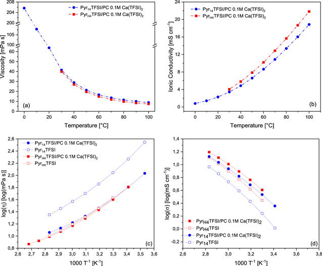
Figure 1. Influence of the temperature on the (a) viscosity and (b) conductivity of the electrolytes based on Pyr14TFSI:PC (blue) and PyrH4TFSI:PC (red), both with 0.1 mol l−1 Ca(TFSI)2. (c) and (d) show Arrhenius plots of the viscosity and conductivity of the electrolytes based on Pyr14TFSI and PyrH4TFSI with Ca(TFSI)2 as well as pure PyrH4TFSI and pure Pyr14TFSI.
Download figure:
Standard image High-resolution imageThe influence of the temperature on the ionic conductivity of the electrolytes is displayed in Fig. 1b. Starting at 0 °C the electrolyte containing Pyr14TFSI is exhibiting a conductivity of 0.8 mS cm−1, which is rising to 3.4 mS cm−1 at 30 °C and to 18.9 mS cm−1 at 100 °C. Analogous, the ionic conductivity of the electrolyte containing PyrH4TFSI is increasing from 4 mS cm−1 at 30 °C to 21.8 mS cm−1 at 100 °C, which is slightly higher than the aprotic one, due to the higher viscosity of the latter one. Additionally, in PILs the ion transport is not only goverend by vehicular mechanisms but also by ion, or more specific, proton hopping. This latter transport is independant of the viscosity, which may explain the stronger increase in conductivity of the PIL.36–39
Near room temperature the IL containing electrolytes display similar ionic conductivity compared to 0.1 M Ca(TFSI)2 in PC with approximately 3 mS cm−1 at 30 °C.35 Figures 1c–1d depict the Arrhenius plots of the viscosity and conductivity of the investigated electrolytes and, for comparison, the pure Pyr14TFSI and PyrH4TFSI. The mixtures with PC and Ca(TFSI)2 are showing the typical "non-Arrhenius" behavior of ILs. Among the two electrolytes, the Pyr14TFSI and PC mixture appears to deviate more from the behavior of the pure IL than that containing the PyrH4TFSI. This is especially true when the viscosities are considered. Very likely, this is due to the general higher viscosity of the Pyr14TFSI, which is more easily reduced when mixed with a low viscosity solvent.
Figure 2 shows the ESW of the investigated electrolytes. The electrolyte containing Pyr14TFSI displays an overall potential window of about 5.1 V, which is the result of a large cathodic (∼−3 V vs Ag) as well as anodic (∼2.1 V vs Ag) stability. The ESW of the electrolyte containing PyrH4TFSI is significantly lower, and equal to 3.2 V. The cathodic stability appears therefore limited by the cation [Pyr14]+ or [PyrH4]+ decomposition, rather than the calcium plating, the lower stability in the latter case being due to the presence of the "free" proton which is getting reduced at −1.1 V vs Ag.18 The anodic stability of both electrolytes, on the other hand, is comparable, suggesting that it is dictated by the reduction of the [TFSI]− anion. It is important to notice that the ESWs of both electrolytes are comparable with those of the pure ILs.40

Figure 2. Electrochemical stability of the investigated electrolytes at room temperature (scan rate of 1 mV s−1).
Download figure:
Standard image High-resolution imageIn order to effectively utilize the investigated electrolytes in combination with AC-based electrodes, the OPV of these electrolytes need to be assessed.41 Obviously, the maximum OPV achievable with AC-based electrodes is lower than the ESW measurement. This is due to the higher reactivity of the AC surface compared to that of the inert Pt electrode utilized for the determination of the ESW.42 Figure 3 compares the maximum OPV possible for AC-based electrodes in the two investigated electrolytes, as obtained by CV measurements. The positive and negative limits have been defined considering the Coulombic efficiency of the process (threshold 98%). It has to be noted that calcium has not been used as electrolyte component for EDLC in the past, partly because the electrosorption of large bivalent ions can be problematic at a given pore size and because of superior transport properties of conventional ions like quaternary ammonium cations.43 As shown in Fig. 3a, the use of the electrolyte containing Pyr14TFSI allows a maximum OPV of 3.3 V, which is resulting from a negative and positive limit of −1.91 V vs Ag and 1.39 V vs Ag, respectively. This OPV is smaller compared to that reported for the pure Pyr14TFSI in combination with the same electrodes (3.8 V), but is comparable with that observed for other mixtures of Pyr14TFSI and alkali metals, e.g. Li and Na, based salts.40 This difference is mainly caused by a shortening of the cathodic stability, suggesting a possible parasitic contribution due to the reduction of the solvent molecules present in the calcium cation complex. By contrast, the cathodic stability of the electrolyte containing PyrH4TFSI is only slightly modified by the use of AC (−0.95 V vs Ag) when compared with Pt electrode (−1.1 V vs Ag) and an ESW of 2.4 V is obtained. The reduction of the free proton of the [PyrH4]+ cation thus appears to be only slightly affected by the nature of the electrode used. As for the anodic stability recorded with AC electrodes, both electrolytes present similar values (about 1.5 V vs Ag) dictated by the TFSI− anion oxidation, about 1 V earlier than with the Pt electrode. These results are comparable to those reported for AC-based electrodes used in combination with neat PyrH4TFSI (Figure S1).40
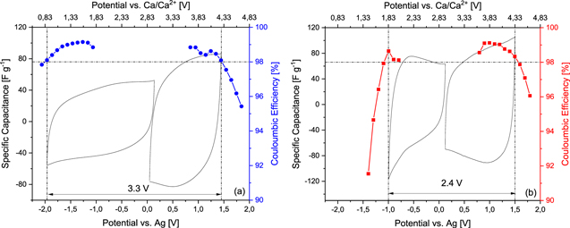
Figure 3. Specific capacitance and Coulombic efficiency obtained by CV at 5 mV s−1 using an AC electrode and the aprotic (a) and protic (b) IL-based electrolytes. The horizontal line represents a 98% threshold in efficiency, the vertical lines mark the potential at which the efficiency falls below 98%.
Download figure:
Standard image High-resolution imageAfter these measurements, EDLCs containing the AC-based electrodes and the two investigated electrolytes have been assembled and tested. The tests have been carried out utilizing the maximum OPV determined in the previous experiments. Figure 4 shows the CVs of the EDLCs containing the two electrolytes. Both EDLCs display the typical rectangular shape characteristic of these devices, and no significant faradic peaks are visible. Overall, the EDLC containing Pyr14TFSI appears to display a better performance than the one containing PyrH4TFSI. The former displays a higher OPV (3.3 V vs 2.4 V) and capacitance (25 F g−1 vs 20 F g−1) than the latter.

Figure 4. (a) Cyclic Voltammetry (scan rate 1 mV s−1) and (b) capacitance retention at different current densities of EDLCs containing the investigated electrolytes. The test have been carried out at 30 °C.
Download figure:
Standard image High-resolution imageAfterwards, CC measurements carried out at different current densities were performed. As shown in Fig. 4, also during these tests the EDLC containing Pyr14TFSI appears to display a better performance than the one containing PyrH4TFSI. At 0.1 A g−1 the device capacitance was equal to 18 F g−1 and 16 F g−1 for the system containing the AIL and the PIL, respectively. Both systems display good capacitance retention up to 1 A g−1. At 2.5 A g−1 however, the device containing the electrolyte based on PyrH4TFSI shows a low capacitance retention, compared to the one based on Pyr14TFSI. This difference could be partially caused by the operative temperature of the experiment (30 °C), which is in proximity of the melting point of the PIL.
Taking these results into account, the use of the investigated IL-based electrolytes in combination with AC-based electrodes appears promising. Both of these electrolytes could be utilized for the realization of Ca-based energy storage devices containing this active material.
In order to investigate the impact of the investigated electrolytes when used in combination with battery materials, we performed CC measurements of TiS2 in Pyr14TFSI:PC (0.1 M Ca(TFSI)2) electrolyte, which displays the highest cathodic stability limit (Fig. 2). A pre-calciated AC CE and a Ag QRE were used, to prevent the cell to be limited by a Ca anode.44
The voltage of the TiS2 electrode for one galvanostatic cycle or prolonged reduction at C/50 in Pyr14TFSI:PC (0.1 M Ca(TFSI)2) at 100 °C is reported in Fig. 5. After an initial decrease from −0.5 to about −1.2 V vs Ag, the voltage nearly stabilizes and the discharge is limited in capacity to 0.8 Ca2+ per formula unit (i.e., 383 mAh g−1 (TiS2) in 40 h). This response differs from that of the same electrode in 0.3 M Ca(TFSI)2 in PC, where the voltage gradually decreases and no plateau is reached.32

Figure 5. Galvanostatic charge/discharge profiles of TiS2 electrodes at C/50 in Pyr14TFSI:PC (0.1 M Ca(TFSI)2) (a) and Pyr14TFSI:PC (b) and 100 °C; X-ray diffraction patterns of the active material after extended reduction or one complete cycle in Pyr14TFSI:PC (0.1 M Ca(TFSI)2) (c) and after extended reduction in Pyr14TFSI:PC (d). The diffraction pattern of pristine TiS2 is reported in Ref. 32 as well in (d).
Download figure:
Standard image High-resolution image
As the current is reversed, the voltage quickly reaches the value of the initial rest potential, showing a high hysteresis. At this point, the current was reversed again in the case of the prolonged reduction and a capacity corresponding to another 0.8 Ca2+ could be passed through the cell (reaching point (A)). In a second cell, the first oxidation was pursued until annulling the net capacity passed through the cell reaching point (B) at 450 mV vs Ag.
To better understand the role of the [Pyr14]+ cation, a prolonged reduction of TiS2 was performed in an electrolyte which does not contain calcium cations (in Pyr14TFSI:PC, Fig. 5b). The voltage response appears very similar to the one obtained in Pyr14TFSI:PC (0.1 M Ca(TFSI)2), though shifted by ≈400 mV towards positive values. This shift can be attributed to a difference in potential of the QRE between the two electrolytes, since a comparable difference is observed for the CEs: −600 mV vs Ag QRE in Pyr14TFSI:PC (0.1 M Ca(TFSI)2) and −150 mV in Pyr14TFSI:PC after 15 h rest (not shown). As the current is reversed after a specific capacity of 383 mAh g−1 has been reached, the voltage increases by more than 500 mV, reaching the cut-off limit, which shows that the hysteresis is important in this electrolyte as well. As in the case of the electrolyte containing Ca(TFSI)2 salt, the reduction could subsequently be extended by a capacity value equivalent to 0.8 Ca2+ in TiS2, reaching point (C).
Ex-situ X-ray diffraction (XRD) patterns are reported in Figs. 5c and 5d for TiS2 tested in Pyr14TFSI:PC (0.1 M Ca(TFSI)2) and Pyr14TFSI:PC, respectively. The diffraction pattern of pristine TiS2 powder is also reported in Fig. 5d for comparison. After extended reduction in Pyr14TFSI:PC (0.1 M Ca(TFSI)2) (pattern (A)), peaks of TiS2 can still be identified at wavenumbers of 1.1, 2.4, and 3.7 Å−1, despite their important broadening. The most intense peak, at a value of 0.57 Å−1 corresponding to an interlayer distance of 11.1 Å, is a consequence of the intercalation of cations in the structure, possibly with concomitant intercalation of PC molecules. It is worth mentioning that using 0.3 M Ca(TFSI)2 in PC electrolyte, a similar peak related to solvent co-intercalation was observed.32 However, the latter was recorded at a higher Q value of 0.68 Å−1 and suggests that [Pyr14]+ cation (larger than PC) can be inserted in TiS2.
After a complete cycle in Pyr14TFSI:PC (0.1 M Ca(TFSI)2) (pattern (B)), the characteristic peaks of TiS2 are still clearly identified despite significant broadening, indicative of reduced crystallite size after discharge and charge. The peak at 0.57 Å−1 is also observed, indicating that the processes occurring in reduction were not fully reversed at oxidation. These results suggest that insertion and de-insertion of cations inside the structure of TiS2 is possible in this electrolyte, as it was shown to occur in PC (0.3 M Ca(TFSI)2).29 However, by contrast with the IL free electrolyte, cycling in Pyr14TFSI:PC (0.1 M Ca(TFSI)2) lead to a higher degree of amorphization of the host structure and only partial removal of the intercalated species upon oxidation (the peak at 0.57 Å−1 being still observed in point (B), Fig. 5c). The XRD data in Fig. 5d reveals quasi total amorphization of TiS2 after extended reduction in Pyr14TFSI:PC. A low intensity peak is still present at 0.55 Å−1 as a remaining of the largest ordering range in the intercalated phase.
Overall, it appears that intercalation of [Pyr14]+ into TiS2 can take place leading to the formation of significant interlayer distances and amorphization. A lower degree of amorphization being reached after reduction in Pyr14TFSI:PC (0.1 M Ca(TFSI)2) than in Pyr14TFSI:PC suggests preferential insertion of Ca2+ with respect to [Pyr14 ]+. Nevertheless, the insertion is not fully selective since the same voltage trend is observed in both electrolytes and similar interlayer distances are obtained upon reduction. These results also differ from the one obtained in Pyr14TFSI free electrolyte, in which the capacity and degree or amorphization reached in reduction are lower than in the electrolytes employed in the present work.
Conclusions
The development of innovative electrolytes is of great importance for the development of advanced Ca batteries. In this work we showed that electrolytes based on mixtures of PC and AIL/PIL containing the salt Ca(TFSI)2 display good transport properties and ESWs comparable with those of electrolytes with similar composition, but suitable for Li- or Na-based systems. The use of these electrolytes in EDLCs with AC electrodes showed to be a viable strategy to obtain devices displaying good capacitances paired with a high reversibility and stability. When AIL-based electrolytes are used, also high voltage devices can be realized. Considering these results, AC appears therefore as suitable material for the realization of Ca-based devices. The use of IL-based electrolytes in combination with TiS2, on the other hand, appears more challenging. In order to build a reliable Ca-based battery device, the active material should either insert Ca2+ selectively, or accommodate the large cation of the IL without damage. We showed that this is not the case for the combination of [Pyr14]+ with TiS2, which is known for having the ability to host a broad variety of species in its structure but gets amorphized upon insertion of the [Pyr14]+ cation. In order to overcome this problem, the use of different IL, e.g. with different cations, and the investigation of other active materials should be considered in the future.
Acknowledgments
AB and TS wish to thank the Friedrich Schiller University of Jena for the financial support. Funding from the European Research Council (ERC) under the European Union's Horizon 2020 research and innovation programme (ERC-2016-STG, CAMBAT grant agreement No 715087) is acknowledged. RD acknowledges support of the Beatriu de Pinós postdoctoral programme of the Government of Catalonia's Secretariat for Universities and Research of the Ministry of Economy and Knowledge (2017 BP 00187). A. Ponrouch is grateful to the Spanish Ministry for Economy, Industry and Competitiveness Severo Ochoa Programme for Centres of Excellence in R&D (SEV-2015-0496). We thank Dr. R. Verrelli for providing us with TiS2 electrodes and for helpful discussion.