

Abstract
Solid-state rechargeable lithium batteries are considered as one of the promising energy storage technologies due to their safety and high energy density. While developing better solid-state batteries is hampered by the poor interfacial compatibility. In this work, one novel design of buffer layer using the Li1+xAlxTi2−x(PO4)3 (LATP) solid electrolyte is reported to address the poor compatibility and big migration gap at the electrode-solid electrolyte interface. Such a facile design works well on facilitating the interfacial ionic inter-diffusion by padding the gap of ionic conductivity between electrode and electrolyte, as well as passivating the electric activity of interface region to avoid the continuously interfacial degradation, hence makes the interface more homogeneous and intimate to deliver the superior electrochemical performance. Moreover, upon cycling, a new carbon-rich interphase is revealed from electron microscopy in the interface region, which probably plays an important role in stabilizing the structure and regulating the electron/ion fluxes. All these findings provide a rewarding avenue to resolve the interfacial issues of solid-state lithium ion batteries and the integrated electronic devices.
Export citation and abstract BibTeX RIS
As the large-scale implementation of portable electronics and development of the electric utility,1–3 Li ion batteries (LIBs) have become one of the most important energy storage technologies. However, the presence of toxic and flammable organic liquid electrolytes and the formation of Li dendrites both amplify the safety issue of current Li ion batteries, which impede the further development of high performance energy storage devices.4–6 Moreover, the narrow electrochemical window of organic liquid electrolytes limits the choice of electrodes for LIBs as well.7,8 To address these problems, replacement of organic liquid with solid-state electrolytes (SSEs) could probably work for the safety and provide a chance to power a wide range of electronic devices from portable devices to heavy locomotives. In the meantime, the use of SSEs in place of organic electrolytes will probably suppress the growth of Li dendrites during battery cycles.9,10 In genergal, the SSEs can be categorized into two classes, namely, the inorganic solid electrolytes including sulfides and oxides, and the solid polymer electrolytes including the PEO, PVDF, PMMA, and PAN based electrolytes.11–16 Recently, some polymer based solid batteries have been reported with good electrochemical performance,17–19 while some fatal flaws accompany, including the temperature dependent electrochemical performance, uncontrollable oxidation at high voltage, and fammablity.20 Whereas, the inorganic solid electrolytes, especially, the oxide solid electrolytes promise the safety, higher energy density, longer cycle life, and lower cost.21 Despite these potential advantages, the realization of the electrochemical performance to conventional LIBs is not achieved, which is mainly due to their relatively lower ionic conductivities and higher solid-solid interface resistance between electrodes and SSEs than the liquid electrolytes. A doable strategy is highly expected to solve the high interface resistance issues in recent research, but has not been achieved yet.
In terms of compatibility, the cathode-SSE interface is technically more challengeable than the Li-SSE interface. Firstly, the SSEs needs to establish series of interfaces in conventional cathodes as they are composites based on active materials, conductive additives, and binders. This takes enough uncertainties either in electrochemistry or physical identification. Secondly, the cathodes undergo the (de)lithiation with different volumetric expansion. This may have a significant impact on the mechanical properties of the interface. Further, because of the crystalline nature of the cathode materials, additional factors come into consideration such as the lattice mismatch with SSEs and space charge regions formed because of the deficiency of cation/anion at the interface.22,23 Many attempts have been implemented to improve the cathode-electrolyte interface compatibilities. Woo et al. introduced the Al2O3 layers onto LiCoO2 (LCO) surface by ALD method, where the coated Al2O3 layers stabilized the surface Co ions resulting in much better capacity retention. However, the interface between pristine LCO and coating layer would degenerate during cycling, so this approach fail to achieve long-life cycling performance.24 Park et al. adopted a solution-based approach, where the LCO particles were coated with a nanometer thick LiI-Li4SnS4. In this case, an intimate contact between the pristine LCO and coating layer resulted in better performance in long cycling and high rate tests, but still could not address the degeneration of connection during cycling in essence.25 It can be seen that it does not work so well by passivating the interfacial reaction with a new relatively stable layer rather than eliminating the effects caused by interfacial reactions.
In this context, we report a novel buffer layer design technology with comprising of the Li1+xAlxTi2−x(PO4)3 (LATP) solid electrolyte and the mixed ionic/semi-electric conductivity Li-ion intercalation compounds, which intimately improves the compatibilities at solid-solid interfaces. The solid-state battery with the architecture of artificial buffer layer exhibits the stable and efficient cycling with a high reversible capacity at a rate of C/10 (LCO cathode ∼ 150 mAh g−1, and LFP ∼ 155 mAh g−1), which sheds new light on the all solid-state battery design, optimization and application.
Experimental
Preparation of LATP
The Li1+xAlxTi2−x(PO4)3 (0 ≤ x ≤ 0.5, especially x = 0.3, LATP) SSEs were synthesized via a modified sol-gel method. The starting materials were LiNO3 (99%, Alfa Aesar), AlNO3·9H2O (AR, General-Reagent), C12H28O4Ti (98%, JK chemical), and H3PO4 (85%, JK chemical). Stoichiometric amounts of the first three chemicals were dissolved in anhydrous ethanol, and 10% excess LiNO3 was added to compensate for Li volatilization during the high temperature preparation. And ∼ 2% excess phosphoric was added to the solution. The solution was evaporated at 70 °C for 12 h to produce the dry-gel and then was calcinated at 300 °C and 800 °C for 3 and 2 h to synthesize the LATP powders. The LATP powders were then uniaxially pressed into pellets under 400 MPa (FY-15, Tian Jing Sichuang, China) and sintered at 1000 °C for 2 h. After that heat treatment, several surface conditioning protocols, including the dry polishing (DP), wet polishing (WP) with sandpapers (600, 1000 and 2000 grit), and second heat treatments, were employed to reduce the interfacial resistance as well as the removing of Li2CO3 and LiOH speciation on the ceramic surface.
Preparation of electrode-LATP composites
Two kinds of electrode-LATP composites were synthesized via a modified sol-gel method. Stoichiometric amounts of the first three chemicals (LiNO3 (99%, Alfa Aesar), AlNO3·9H2O (AR, General-Reagent), C12H28O4Ti (98%, JK chemical)) were dissolved in anhydrous ethanol, and 10% excess LiNO3 was added. Before adding of phosphoric acid (H3PO4 (85%, JK chemical)), an electrode material (LiCoO2 (99.8%, Aladdin) or LiFePO4 (BTR)) with the mass ratio to LATP powders of 1:5 was added into the solution. After the electrode powders dispersing in the solution homogeneously, the phosphoric acid was added to the solution as the same amount of the LATP preparation process. The solution was evaporated at 70 °C for 12 h to produce the dry-gel and then was calcined at the various temperature in the range of 450 °C– 800 °C to get the electrode-LATP composites.
Characterizations
The phase analysis was performed with a powder X-ray diffraction (XRD) (D2 Phaser Bruker) using Cu Kα radiation of λ ∼ 0.15418 nm, and Fullprof suite software. The morphology of the powder samples was examined by a scanning electron microscope (SEM) (XL 30 S-FEG, FEI Co.) and a transmission electron microscope (TEM) (JEM-2011 electron microscope). The surface morphology of the LATP ceramic pellet samples were examined by an atomic force microscope (AFM) (Bruker Dimension Icon). The valence states of transition metal elements in the composites were analyzed by X-ray photoelectron spectroscopy (XPS) with X-ray source of Monochromated Al Kalph 150 W (ESCALAB 250, Thermo Fisher Scientific, USA). The band gaps of the composites were examined by ultraviolet visible absorption spectrum (UV–vis.; Cary 5000 UV spectrophotometer). The interface condition of before and after charge-discharge composite cathodes were observed by optical microscope (ZEISS, scope A1), SEM and the FEI Cs-corrected Titan Chemi STEM with high-angle annular dark-field (HAADF) imaging and energy dispersive X-ray spectroscopic (EDS) chemical element mapping techniques. The TEM lamellae for post-mortem analysis are prepared by FEI Helios NanoLab DualBeam microscope.
Preparation of composite cathode
Two kinds of composite cathodes were prepared with LiFePO4 and LiCoO2 as electrode materials. Firstly, the electrode material, carbon black, and binder PVDF were mixed in a 7:2:1 mass ratio. The homogeneously mixed slurry was done in a mortar for 30 min. Then the N-Methyl pyrrolidone (NMP) was added as solvent in the mixed powders, and the mixture was continuously mixed for another 20 min. The resultant slurry was spread onto the Al foil. After drying, those sheets were clipped into pellets with 12 mm in diameter as pristine electrodes. Then, the electrode-LATP composites, and PVDF were mixed in an 8:2 mass ratio to coat onto the as prepared electrodes as the composite buffer. Thirdly, following the same process, the LATP powders, and PVDF were mixed with NMP as solvent to coat onto the dried composite buffer layers. Subsequently, those dried as-prepared composite cathodes were uniaxially pressed under a pressure of 520 MPa to ensure the dense interface contacts. After all these procedures, the composite electrodes were put into a vacuum oven at 100 °C for 24 h to evaporate the residual NMP and the water absorbed during the preparation.
Electrochemical characterization
To measure the ionic conductivity of the LATP SSEs, we deposited the Au thin films on both sides of the ceramic discs as the block electrode. The electrochemical impendence spectroscopy (EIS) was performed in a frequency range of 1 MHz to 100 mHz (Solartron SI 1287 electrochemical interface and SI 1206 impedance/gain-phase analyzer). Ionic conductivities were calculated through σ = L/(Z × A), where Z is the impedance for the real axis in the Nyquist plot, L is the LATP ceramic disc thickness, and A is the surface area. The activation energies were obtained from the derived conductivities as a function of temperature using the Arrhenius equation. To prepare the solid-state batteries with the composite cathode, we employed Li metal as anode that was previously dipped into the liquid electrolyte (EC:DEC = 1:1, LiPF6) for surface wetting (about 1 μL liquid electrolyte remained). The remained trace amount of liquid electrolyte on Li metal foil facilitates the contact with the LATP SSE through the separator (Celgard 2300). Note that in this work the interfacial modification was focused on the cathode and solid-state electrolyte interface. Thus, the reduction of Ti4+ in LATP due to the presence of lithium anode was avoided by separator which has no effect on investigation of the buffer layer between cathode and solid-state electrolyte. The charge-discharge tests were measured in a voltage range of 3 to 4.5 V for LiCoO2 and 3 to 4.2 V for LiFePO4 composite cathodes, respectively. The as-prepared solid batteries were tested under a rate of C/10 at room temperature (LAND, Shenzhen, CT-2001A, China).
Results and Discussion
The NASICON type Li1+xAlxTi2−x(PO4)3 (LATP) SSEs26 were successfully synthesized with high ionic conductivity of 1.048 × 10⁻⁴ S cm−1 for x = 0.3 at room temperature. The details of LATP characterizations are shown in Supporting Info. (Figs. S1–S4 and Table SI is available online at stacks.iop.org/JES/167/100528/mmedia). The ionic conductivity indicates that the as-synthesized LATP SEs could potentially meet the requirements for the application in all solid-state batteries. However, to build a solid-state battery, it needs to well address the electrode-electrolyte interface issue. In term of cathode-solid electrolyte interface, a stable intermediate as the buffer layer between them are highly desired to afford the possible interface change/stress. The good interface contacts need to be considered in both physical and electrochemical ways, which mean that the wettability of two solid phases is not like liquid/solid interface and the electric activity and ionic conductivity also affect the evolution of the interface. Through introducing a stable and ionic/semi-electric conductive intermediate between cathode and SE can prevent the interfacial region from degradation. As presented in Fig. 1a, the sol-gel method is employed to mix the LATP with the active materials homogenously. After the heat treatments the LATP-LCO and LATP-LFP composites are obtained. Figure 1b demonstrates the preparation and working mechanism of the proposed buffer layer, by which, the ionic conductivity gap is obviously reduced between cathode and SSE. As shown in the yellow line, the Li+ migration becomes much easier as well as much less driving force (represented by energy) during Li+ migration through the electrode-solid electrolyte interface region.
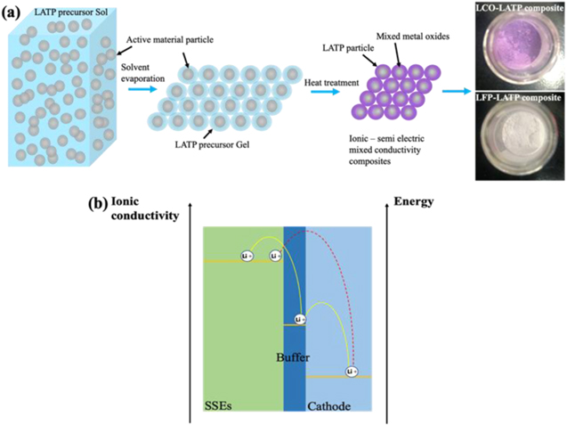
Figure 1. Schematics of the buffer layer preparation and working mechanism. (a) Synthesis of ionic/semi-electric mixed conductive buffer materials. (b) Schematic illustration of the ionic diffusion through the interface region with/without buffer layer.
Download figure:
Standard image High-resolution imageFigures 2a, 2b presents the XRD pattern of the as-prepared LCO-LATP and LFP-LATP composites annealing at 700 °C. From the XRD patterns, the main peaks could be assigned as the LATP phase, but the intensity change should be ascribed to the superimposed peaks of LATP with small amount of Li2O and/or metal oxides (TiO2, Co3O4 or CoO2, and Fe2O3). It should be noted that the standard characteristic peaks of Co3O4 and CoO2 phases superimpose almost at the same angle, so it cannot be discriminated only from XRD patterns. The XRD patterns of pristine LCO and LFP samples and LCO-LATP composites synthesized at different temperatures can be retrieved in Figs. S5, S6. Figures 2c–2f presents the SEM images of LCO-LATP and LFP-LATP composites, where the contrast difference could be plausibly referenced to identify the majority dark particles as the LATP phase. While the minority white particles on the surface and in the bulk are unclear, probably the cobalt-based or ferric compounds as attested from the XPS results in Fig. 3, where the chemical states of Co and Fe ions change obviously.
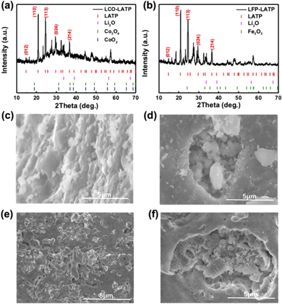
Figure 2. Structure and morphology of electrode-LATP composite samples. (a) and (b) The XRD patterns of LCO-LATP and LFP-LATP composites annealing at 700 °C. The characteristic peaks of LATP, Li2O, Co3O4, CoO2 and Fe2O3 are shown as well for phase identification, where the characteristic peaks of Co3O4 or CoO2 are overlapped. (c)–(f) are SEM images of LCO-LATP and LFP-LATP composites respectively.
Download figure:
Standard image High-resolution image
Figure 3. The XPS analysis of electrode-LATP material composites. The XPS images of (a) and (b) O1s orbital in LCO-LATP and LFP-LATP composites. (c) and (d) The Ti 2p orbital in LCO-LATP and LFP-LATP composites.
Download figure:
Standard image High-resolution imageFigure 3 shows the XPS results of O 1s and Ti 2p orbitals in LCO-LATP and LFP-LATP composites. As demonstrated in Figs. 3a, 3b, there are three types of O peaks: the peak at 533 eV corresponding to the P-O band from the PO43− radical in LATP, and the other two peaks contributed by the Co–O band from Co4+ at the position of 531.2 eV and the Fe–O band from ferric state locates at the position of 530.7 eV, which demonstrates that part of the initial Co3+ and Fe2+ ions have been oxidized completely during the preparation. In Figs. 3c, 3d the XPS spectra of Ti ions indicates the Ti4+ ion with the 459.8 eV of Ti 2p3/2 orbital and 466 eV of Ti 2p1/2 orbitals in LCO-LATP and LFP-LATP composites. It could be inferred that the Ti4+ ion remains unchanged to ensure the ionic conductivity of LATP phase in the electrode-LATP composites (More details see Fig. S7).
The electrochemical stability of the as-prepared LCO-LATP and LFP-LATP composites is then characterized by cyclic voltammetry (CV). Figures 4a, 4b presents the CV results of both composites within a potential range of 2.8 to 5.0 V. The magnified insets correspond to the first delithiation process. From the yellow regions of the insets, the extraction of Li+ ion begins at about 4.0 V in the first cycle, while this delithaition behavior disappears in the following cycles as shown in Fig. S8. It means that after a simple activation, the composites become electrochemical stable at such high voltage ranges above 4.0 V. These CV results match with the charge-discharge profiles as shown in Figs. 4c, 4d, where the as-prepared LCO-LATP and LFP-LATP composites demonstrate a delithiation behavior in the first charging with the capacity of ∼ 55 mAh g−1 around 4.1 V. The composites contribute nearly no capacity with only a capacitive behavior in the subsequent cycles. Hence, after electrode activation, the as-synthesized composites display the electrically inactive feature within the working potential range from 3.0 to 4.5 V that is the exact electrochemical window of LFP and LCO batteries.
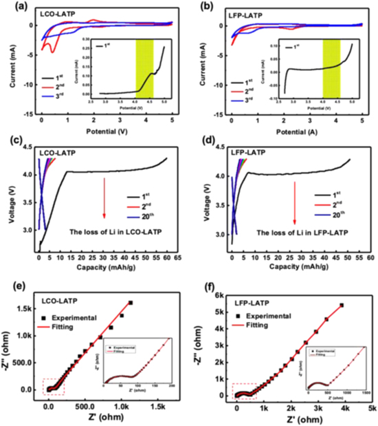
Figure 4. Electrochemical performance of the LCO-LATP and LFP-LATP composites. (a) and (b) Cyclic voltammetry tests within a potential range from 0 to 5.0 V. The insets present the magnified plots of the 1st cycle within a potential range from 2.8 to 5.0 V. (c) and (d) Charge-discharge profiles between 3.0 and 4.3 V. (e) and (f) EIS measurements with fitting results of the corresponding composites.
Download figure:
Standard image High-resolution imageAs the UV–vis. absorption spectroscopy shown in Fig. S9, the calculated indirect optical band gaps of LCO-LATP and LFP-LATP composites are 3.24 eV and 3.05 eV (absorption edges at ∼ 400 nm), respectively, indicating a wide bandgap semiconductor feature (semi-electric conductivity). This lower electric conductivity could probably suppress the charge transfer process, thus prevent the continuous degradation of surface/interface region if the composite performs as a buffer layer between electrode-electrolyte interface. With this composite as buffer, the gradient Li concentration is intentionally built between electrode and solid electrolyte to ensure the ionic transports. Moreover, the newly-introduced Li2O as shown in Figs. 2a, 2b is highly possible to contribute to the capacity at about 4.1 V in a metal-catalytic environment (e.g.: Co ions)27,28 as shown in Figs. 4c, 4d. If using as the buffer layer, this Li extraction first activates the Li+ ion diffusion pathway, and then helps on the self-reorganization inside the interfacial region to strength the interfacial connections (similar to the sintering aids of Li2O upon high-temperature synthesis29,30). Apparently, it, in turn, endows the buffer layer with self-healing feature to promise the long cycle performance of solid batteries. Figures 4e, 4f shows the EIS Nyquist plots of LCO-LATP and LFP-LATP composites, where the tests are performed in the organic electrolyte-based half-cell. According to the slopy lines in low frequency region, the Li+ diffusion coefficient (D) can be evaluated to be 1.24 × 10⁻¹⁰ cm2 s−1 and 3.43 × 10⁻¹² cm2 s−1 for the LiCoO2 and LiFePO4 composites (details see Note S2 and Figs. S10a, S10b), respectively, which are higher than that of cathode themselves.31,32 Therefore, the LATP/electrode composites possess a kind of semi-electric/ionic mixed conductivity to guarantee both of the Li+ diffusion and charge transfer features accordingly.
Then, the composites are sandwiched as a buffer layer between the LiCoO2 (or LiFePO4) and LATP SSE as an integrated unit (composite cathode-SSE part), which could work as a all solid-state battery by adding the encountered Li anode as shown in Fig. 5a (Note that in terms of the metallic Li-SSE interface, problems are significantly resulted from the Li itself due to its boneless structure and high electrochemical/chemical activities. Hence, different solutions are needed.). Figure 5b shows the composite LiCoO2-SSE part with the diameter of d = 11.85 mm and the thickness of l = 0.13 mm. Then the composite cathode-SSE is sliced using FIB and the full cross section is firstly observed under optical microscopy as shown in Fig. S11, where no obvious voids or cracks are observed at that two interfaces (between Layers 1 and 2, and Layers 2 and 3 in Fig. 5a). Same conditions could be referred to the SEM image as shown in Fig. 5c, where there are no clear physical boundaries between Layers 1 and 2, as well as Layers 3 and 2 as shown in Fig. S12. Then the SEM in combination with EDX spectroscopy are used to analysis the interfacial morphology and elemental distribution, where Figs. 5d ∼ 5h presents the elemental mapping results of O, Ti, Co, C and Al, respectively. As present in Figs. 5e, 5f, 5h, from the Al side there are obviously elemental distribution gradients, where it increases for the Ti ions and decreases for the Co ions distributions. The most important point is that the irregular local boundary could be observed between the LiCoO2 and buffer layer, which implies the imbedded structure near the interface (similar case in LiFePO4-SSE interface as shown in Fig. S13). Furthermore, in Fig. 5g the mapping results indicate that there is a homogeneous C distribution in the whole SEM image, which is probably resulted from the contamination and the binder PVDF. From the Supporting Figs. S13d, S14, similar C distribution is observed at the LFP based cathode-SSE part, the influence of which will be discussed later. From the above analysis, it could be inferred that the interfacial structure turns from a conventionally sharp point-to-point contact into a novel plane-to-plane imbedded contact (transition zone) at the interface region. Within the buffer layer, a small amount of none SSE materials, e.g. the metal oxides, could play an important role in accommodating the Li storage and absorbing the interfacial stress during electrochemical cycles. Such an imbedded interfacial morphology is of significance in improving the interfacial compatibility and thus good electrochemistry is expected for the as-prepared solid-state batteries.
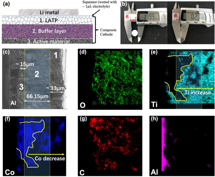
Figure 5. Physical structure of the composite cathode-SSE part. (a) Schematic illustration of the solid-state battery unit, where Numbers 1 ∼ 3 represent the whole composite cathode-SSE part, including the LATP SSE (1), LCO-LATP buffer layer (2) and LCO cathode (3). (b) The diameter and thickness of the composite cathode (including the LATP, composite buffer and cathode layers) measured by Vernier caliper. (c) SEM image of the composite cathode with full cross-section, where the main buffer layer is labeled with the dotted yellow rectangular. Layers 1, 2 and 3 are the same as the corresponding sections in (a), respectively, and the thickness of each sections are marked. (d)–(h) The elemental mappings of O, Ti, Co, C and Al in the composite cathode-SSE part, respectively, where it could be seen the homogeneous distribution of C and the irregular phase boundaries in the composite cathode-SSE part.
Download figure:
Standard image High-resolution imageTo reveal the underlying contribution of buffer layer, in situ EIS is performed as shown in Fig. 6. Figure 6a demonstrates that the LiCoO2 based cathode-SE part shows the stabilized interfacial impedance after its fluctuations in the first three cycles. The EIS fitting result is present in Fig. 6b, from which the Rp1 (55.24 Ω) and Rp2 (161 Ω in the 10th cycle) refer, in principle, to the two solid-solid interfacial resistances between the LiCoO2 and buffer layer (Rp1) as well as the interface between the LATP and buffer layer (Rp2). As shown in Fig. 6a, the constant semicircle intercepts of EIS results at the medium frequency indicate the stabilized resistances, which suggests the improved interfacial compatibility after the first three cycles. Meanwhile, the above interfacial resistances are comparable to that of the organic electrolyte-based cells employing the same LCO and LFP electrodes as shown in Figs. S15b, S15d (SI). These EIS results show that the imbedded interface with the low interfacial impedances should be the main contributions to the superior electrochemical performance.
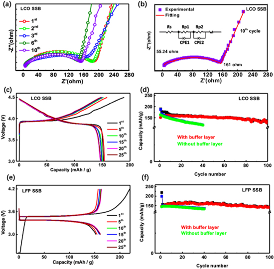
Figure 6. Electrochemical performance of the as-prepared LiCoO2- and LiFePO4-based all solid-state batteries at room temperature. (a) The in situ EIS results of solid battery with LiCoO2 composite cathode in the initial charge-discharge cycles. (b) The EIS fitting result of the 10th cycle and the measured two interfacial resistances of Rp1 and Rp2 with cycles. (c) and (e) The galvanostatic charge-discharge profiles, (d) and (f) the capacity retention of the solid-state batteries at C/10 using LiCoO2 and LiFePO4 as the electrode materials, respectively.
Download figure:
Standard image High-resolution imageFigure 6 presents the electrochemical performance of the composite cathode-SSE parts and Li anode, where the electrode material has a mass loading of ∼3 mg cm−2 (LCO and LFP). At C/10, the solid-state batteries deliver the initial charge capacities of ca. 180 mAh g−1 and 220 mAh g−1 for LCO and LFP based cells, respectively. It could be seen that in the formation charging, the LFP electrode delivers a capacity more than its theoretical values, indicating the necessary contribution from the buffer layer which, however, seems less significant in LCO based solid cell. This electrochemical contribution from buffer layer diminishes as soon as possible after charging as shown in Figs. 4c, 4d. After the formation cycle, the LCO and LFP solid-state batteries presented stable cycling capacity around 155 mAh g−1 and 160 mAh g−1 as shown in Figs. 6c, 6e. After 25 cycles, both solid batteries still deliver the capacity more than 150 mAh g−1. These LCO and LFP based cells deliver the comparable electrochemical performance with these in traditional organic cells as shown in Figs. S15a, S15c. Moreover, their performance is obviously better than these solid batteries without buffer layer as shown in Figs. 6d, 6f and S16 (SI). In specific, Fig. S16 presents the galvanostatic charge-discharge profiles without buffer layer, from which the poor capacity retention is shown. This implies the necessary role of buffer layer playing in stabilizing the electrochemical performance. Through buffer layer, the ionic conductivity decreases while the electronic conductivity increases gradually from the SSE to cathode as shown in Fig. 1b. The ionic/electric conductivity demonstrates a gradient evolution that is totally different from the solid batteries without buffer layer, which have a big gap in electric/ionic contacts. The buffer layer effectively bridges the cathode and SSE not only in physical morphology, also in Li transport feature, converting the sharp point-to-point contact (without buffer layer) to a more homogeneous and intimate transition zone. Furthermore, upon the initial delithiation, the Li extraction from the buffer layer firstly establishes the Li diffusion trajectories, then improves the connection inside the interface region, and finally compensates the Li consumption by side reactions to mitigate the interfacial stress. In subsequent cycles, the LFP cell could maintain the capacity after 100 cycles while a little capacity loss is found in the LCO based cell. This difference possibly reveals the different interfacial stabilities, where the LFP solid battery could build a relatively more stable interphase with respect to that of the LCO solid battery.
After 100 cycles, the LCO based solid battery is de-assembled and sliced into nanosheets using focusing ion beam (FIB) technique for post-mortem analysis as shown in Figs. 7a–7c and S17 (SI). As shown in Fig. 7c, different particles without pulverizations after 100 cycles are adhered together with the unidentified black intermediates, which should be generated from the side reactions upon cycling. The contrast difference from Fig. 7c reveals the potentially interfacial degradations, especially the visible black intermediates that will lead to the distortion/expansion of the interface region with respect to the uncycled one as shown in Figs. S18, S19 (SI). Figures 7d–7g presents the elemental mapping of O, Ti, Co and C in cycled LCO batteries (also refers to Figs. S20, S21), and Fig. 7i demonstrates an overlaid elemental mapping of the interface region. It can be seen the homogeneous distribution of O in the whole image as shown in Fig. 7d. The elemental Co exhibits the main contrast in the electrode material region and very weak contrast in the buffering layer region, while the elemental Ti distributes overwhelmingly in the buffer region just as the similar results in Figs. 5e, 5f, S18 and S19 (see Fig. S13 for LFP). Hence, a clear electrochemical interface could be depicted as shown in Figs. 7g, 7i, which has an irregular morphology with the carbon-rich and O-poor intermediates inside. Such intermediates are probably generated during cycles, that is, the formation of solid electrolyte interphase (SEI, if so, much different from the conventional concept). Then the electron energy loss spectrum (EELS) of C is acquired in the interfacial region before and after cycling as shown in Figs. S19b, 7h. From the EELS, there is no obvious change of C in carbon-rich and O-poor intermediates around the interface (distribution and valence) at the beginnings. The EELS results after cycling indicates the chemical valence change of C as marked from C1 to C5 sites in Fig. 7c. The C in Sites C1, C2 and C3 remains unchanged. While the C in Sites C4 and C5 changes significantly to be the amorphous C as evidenced in Fig. 7h. The C at Sites C4 and C5 is located near or almost at the interface edge, which has the most intimate connection with the Co ions. Therefore, these accumulated C interphases should be the by-products as the main components of SEI in the solid-solid interface. By comparing the elemental mapping results on C, of special interest is that the C inside the solid battery demonstrates an agglomerated trend along with the electrochemical cycle, which migrates towards the boundary of interface region and probably plays as a bridging role in connecting the electrode with SSE to assure the fast transport of Li+ + e−. This also implies that the ideal solid-solid heterostructure in solid battery will probably burden tremendous stress in the solid-solid interface upon cycling, especially during long cycles. The trade-off in the solid-solid interface, such as the buffer layer here is probably the best way to design and ultimately make the solid battery feasible.

Figure 7. Post-mortem STEM image with elemental mappings of the cycled LCO composite cathode. (a) and (b) The schematic illustration of the slicing procedure around the boundary between the LCO cathode and LCO-LATP buffer layer using FIB technique. (c) The STEM-HAADF morphology of the above-mentioned interface region. The interface region is marked with dotted red rectangular. (d)–(g) and (i) Element mappings of the O, Ti, Co, and C, where the C-rich area is labeled for clear view. (h) The C EELS spectra in the range marked by red arrow in (c). (i) The combined TEM elemental mappings in the boundary between the LCO cathode and LCO-LATP buffer layer.
Download figure:
Standard image High-resolution image
After all, the interfacial characterizations show that (1) the solid-solid interface exists, however without clear boundary and connections. Especially, converting the conventional point-to-point contact to the imbedded transition zone in the interface region facilitates the ionic conductivity and thus enhance the electrochemical performance of solid batteries; (2) it could be seen from the cycled interface that the interfacial region experiences the obvious side reactions with structural changes as shown in Figs. 5, 7, S18, and S19. Therefore, building rational interfacial structure to afford the stress and by-products, such as the buffer layer here, still challenges the stability and safety of solid battery technology; (3) Figs. 7c, 7g manifests that there is a carbon-rich interphase formed at the solid-solid interface between LiCoO2 and buffer layer after cycling. This is different with the initially homogeneous distribution of C in the interfacial region. These carbon-rich and O-poor intermediates are undoubtedly of significant help on improving the electric conductivity during long cycles, while their formation kinetics are still unclear. Furthermore, as shown in Fig. 6, the capacity retention of LCO cell is not as good as that of LFP cell, which should be largely ascribed to the severe catalytic effect of surface Co ions in the LCO electrode.33,34
Conclusions
In summary, the as-prepared buffer materials by mixing the LATP with LiCoO2 and LiFePO4 exhibit the mixed ionic/semi-electric conductivities and the related Li diffusion coefficients are estimated to be 1.14 × 10⁻⁹ cm2 s−1 and 4.42 × 10⁻¹¹ cm2 s−1, respectively. This buffer material effectively pads the ionic/electric gaps between cathode and SSE, resulting in the fast Li+ migration as well as the less stress/strain in the interface. Moreover, the interfacial degradation might be passivated rather than the continuous side reactions due to the low electronically conductive buffer layer on cathode material surface. The solid-state batteries employed the buffer layer display superior capacity retention and cyclability.
Using the buffer layer, the interfacial connection turns from a conventionally sharp point-to-point contact into a novel plane-to-plane imbedded contact (transition zone) that makes the ionic/electronic transport more homogeneous in the interface. Then in the interfacial region, a new carbon-rich interphase is formed after cycling, which probably plays an important role in optimizing the structure and performance of the solid batteries. All these findings provide new insights to understand and ultimately control the interface engineering between electrode and solid electrolyte in solid Li-ion batteries.
Acknowledgments
The authors thank the funding supports from the National Key Research and Development Program of China (no. 2019YFA0705700), the National Natural Science Foundation of China (grant no. 11704019), the Hundreds of Talents program of Sun Yat-sen University and the Fundamental Research Funds for the Central Universities (19lgzd05).