
Abstract
Lithium ion battery failure occurs across multiple length scales. In this work, the properties of thermal failure and its effects on electrode materials were investigated in a commercial battery using a combination of accelerating rate calorimetry (ARC) and multi-length scale X-ray computed tomography (CT). ARC measured the heat dissipated from the cell during thermal runaway and enabled the identification of key thermal failure characteristics such as onset temperature and the rate of heat generation during the failure. Analysis before and after failure using scanning electron microscopy (SEM) and X-ray CT were performed to reveal the effects of failure on the architecture of the whole cell and microstructure of the cathode material. Mechanical deformations to the cell architecture were revealed due to gas generation at elevated temperatures (>200 °C). The extreme conditions during thermal runaway caused the cathode particles to reduce in size by a factor of two. Electrode surface analysis revealed surface deposits on both the anode and cathode materials. The link between electrode microstructure and heat generation within a cell during failure is analysed and compared to commercially available lithium ion cells of varying cathode chemistries. The optimisation of electrode designs for safer battery materials is discussed.
Export citation and abstract BibTeX RIS

This is an open access article distributed under the terms of the Creative Commons Attribution 4.0 License (CC BY, http://creativecommons.org/licenses/by/4.0/), which permits unrestricted reuse of the work in any medium, provided the original work is properly cited.
With high energy densities and favourable ageing characteristics, the rechargeable Li-ion battery is rapidly gaining traction for high-energy applications such as power sources in electric vehicles.1 However, when subjected to unfavourable conditions, Li-ion cells are liable to undergo failure owing to their highly energetic and flammable constituent materials;2 this has been demonstrated recently by several high-profile failures.3−4 As such, improvements to their safety is critical, especially with the increasingly demanding range of applications proposed.5,6
Overcharging or internal short circuits (ISCs) can lead to battery temperatures well above manufacturer ratings.7,8 At a critical temperature, a chain of exothermic reactions can be triggered and the battery will undergo rapid self-heating. If the battery is inadequately designed to dissipate the heat generated, it will catastrophically fail. This failure mechanism is known as thermal runaway and can be characterised across multiple length scales: from electrode microstructure to the whole cell and pack level.9−10
Several investigations to predict battery failure behaviour and the thermal runaway mechanism have been conducted both on the component and cell level, using accelerating rate calorimetry (ARC). Based on kinetic parameters determined from ARC tests, Dahn et al.11 developed models to study reaction mechanisms and thermal stabilities of small amounts of various materials at a component level. Kinetic parameters for the decomposition of the SEI film layer, the reaction between lithiated graphite and electrolyte and the cathode decomposition reaction12 revealed that the onset temperatures and quantity of heat generated differs with electrode composition.13,14 Furthermore, Spotnitz and Franklin15 summarised the kinetics of anode, cathode and electrolyte decomposition reactions at elevated temperatures. This was extended to a cell level by Hatchard and Kim16,17 who established a model to predict the behaviour of large format cylindrical Li-ion batteries.
A number of exothermic reactions which occur at different temperatures have been determined as major sources of heat during failure. At 90 °C, the solid electrolyte interphase (SEI) layer begins to decompose and self-heating is initiated.11,18 This is closely followed by a reaction between the anode active material with the electrolyte and binder at approximately 100 °C. The polymeric separator, which melts between 120 °C–140 °C results in a small decrease in cell temperature.19 At elevated temperatures, 170 °C–235 °C,15 the cathode active material begins to decompose and generate oxygen.20,23 The released oxygen may oxidise the electrolyte and exothermically react with the anode active material, substantially increasing the overall temperature of the battery. Gases (such as H2, CO, CH4, C2H6, C2H4)21 released from these reactions may then begin to combust at high temperatures if an ignition source is present, resulting in a fire or explosion.
To decipher the sequence and severity of these reactions, ARC measurements of high-power Li-ion cells in an 18650 format have been widely reported. These studies quantify failure by determining the onset temperature (the critical temperature at which thermal runway is initiated) and the rate of heat generation during failure. Experiments in literature are primarily conducted on commercial cells with cathode materials such as LiCoO2 (LCO), Li(NixMnxCox)O2 (NMC) and LiFePO4 (LFP)22−23 each showing varying onset temperatures of 150 °C, 170 °C and 195 °C, respectively.21 Studies have also revealed that high states of charge (SOCs) aggravate exothermic reactions, where the self-heating rate increases exponentially with SOC.24 For a LiNi0.8Co0.15Al0.05O2 (NCA), 1 Ah capacity cell, Abraham et al.25 reported self-heating initiated at the anode at 84 °C, and surface deposits on both the anode and cathode surfaces were found using X-ray photoelectron spectroscopy (XPS). Changes to the crystal structures, i.e. evidence of oxygen loss, were not identified.
In addition to the thermodynamic stability of components and cell size, the composition and morphology of the electrode materials directly influence cell behaviour during failure.13,14,21,26 Surface dependent features such as specific surface area play a large role in determining the degree of heat generation during failure.27 Smaller particles have been shown to release oxygen at a higher rate during decomposition, corresponding to an increase in heat generation, and greater loss of mass during failure. At high temperatures the decomposition rate of the cathode increases linearly with great particle surface area.28 Jiang and Dahn29 have demonstrated a reduction in particle size of LiCoO2 from 5 μm to 0.8 μm resulted in a lower onset temperature.
The fast kinetics of the exothermic reactions leading up to thermal runaway (within hundreds of seconds) require high-speed techniques to record developments within a battery during failure. High speed operando X-ray imaging has previously been used to track structural deformations leading up to and during thermal runway in 18650 format cells.9,10 Additionally, X-ray CT with a multi-length scale approach has been used to analyse Li-ion battery materials30 and demonstrated as an effective diagnostic tool for cells during.31,32 and after failure.10
In this work, ARC in combination with lab-based multi-length scale X-ray CT imaging is used to understand the failure of a commercial Li-ion battery. Image based analysis is used to quantify the changes in particle morphologies of the cathode, before and after failure, to investigate the effect of this design feature on battery safety.
Experimental
Thermal runaway
A commercial 2.2 Ah 18650 battery LGDAS31865 P313K083A6 LG Chem, South Korea), consisting of a Li(Ni0.6Mn0.2Co0.2)O2 cathode, polymer separator and graphite anode, was fully charged to the maximum rated voltage, 4.2 V at 1 C via a constant-current constant-voltage (CCCV) charging protocol. Prior to conducting the ARC experiments, the OCV was checked to ensure no capacity fade had occurred. The thermal abuse test was performed using ARC inside a calorimeter (Phitec Battery Test Calorimeter, HEL Group, Herts., UK) using the heat-wait-search method. Once the battery had reached a start temperature (25 °C) the following procedure was initiated: the calorimeter increased the temperature in discrete steps (5 °C), waited for any thermal transients to decay and subsequently monitored the battery temperature. If in this time, the temperature remained unchanged, up to a threshold value (0.02 °C min−1), the calorimeter continued to increase the temperature by 5 °C until self-heating was detected.
Multi-scale lab-based X-ray tomography
Tomographic reconstructions of varying length scales and sample sizes were produced using three different lab-based X-ray CT systems; a Nikon XT 225 (Nikon Metrology, Tring, UK, a Zeiss Xradia Versa 510 and a Zeiss Xradia Ultra 810 (Carl Zeiss XRM, Pleasanton, CA, USA).
Pre- and post-failure X-ray CT images of the whole battery were captured using a Nikon XT 225: the geometric configuration of the radiographic scans resulted in a pixel resolution of 38 μm and 35 μm, for the pre- and post-failure scans, respectively. An accelerating voltage of 210 kV with a tungsten target was used to generate 3176 projections. The acquired datasets were reconstructed using CT Pro 3D software with a built in filtered back projection algorithm with subsequent data was visualised using Avizo Fire 9.2.
Prior to the pre- and post-failure X-ray micro-CT scans and SEM, the cylindrical cell casing was removed using a pipe cutter inside an argon glovebox. The spiral wound layers were carefully unrolled and the separator, positive and negative electrodes were isolated from one another. The electrodes were washed with dimethyl carbonate to remove any electrolyte and left for two days to dry. The fresh cell was discharged to 0 V before being dismantled. Electrode samples were taken from the centre of the unrolled cell. SEM samples were prepared by cutting a ∼5 mm electrode square while micro-CT samples were prepared by cutting a ∼3 mm triangle from the corner of an electrode and attaching (5-minute epoxy, ITW Devcon, USA) it to the end of a pin attached to the sample holder. Details of the parameters used to capture the microscale images and the pixel resolutions achieved are summarised in Table I.
Table I. Summary of the multi-scale X-ray CT scanning parameters used in this work.
| Macroscale | Microscale | Nanoscale | |||
|---|---|---|---|---|---|
| Parameter | Pre-failure | Post failure | Pre-failure | Post failure | Post failure |
| Voltage (kV) | 210 | 80 | 100 | 35 | |
| Projections | 3176 | 1601 | 1301 | 1601 | |
| Exposure time (s) | 1 | 38 | 35 | ||
| Pixel size (μm) | 38 | 35 | 0.48 | 0.37 | 0.0631 |
Nanoscale post-failure analysis of the positive electrode was imaged using an X-ray nano-CT system (Zeiss Xradia Ultra 810). Electrode samples for nanoscale characterisation were prepared using a laser micro-machining procedure to achieve the desired sample size.33 A resolution of 63.1 nm was achieved using a Cr target with an accelerating voltage of 35 kV and a tube current of 25 mA. Further details of the image scanning parameters are summarised in Table I. For both micro- and nano-scale CT, tomographic reconstruction was achieved using the XM Reconstructor software suite (Zeiss, Pleasanton, CA, USA).
Reconstructed data was processed using Avizo Fire 9 software (FEI VSG, France). After reconstruction a non-local means filter was applied to the images to reduce noise and preserve phase boundaries as shown in Fig. 1. Phases were separated based on their grey scale values, where weakly attenuating materials are displayed in shades of grey and highly attenuating materials in white. Binary images and volume renderings as shown in Fig. 2, are subsequently used for measurements of porosity and PSD using Avizo Fire 9's label analysis tool. Image processing in the context of lithium ion battery materials requires preprocessing to enhance particular features by using a set of filters. This procedure is often performed to prepare data for threshold-based binarization. The second step is to distinguish phases by assigning each voxel to a particle or pore phase based on the measured grayscale value. This is often sensitive to variations such as enhanced edge contrast and so the choice of thresholding approach becomes important for particular data sets and their features. Detailed descriptions of various image analysis techniques are provided specifically for lithium ion battery electrodes in the following reviews.34,35 Analysis programmes such as ImageJ (National Institutes of Health, USA) or Drishti (https://github.com/nci/drishti) provide suitable open source image segmentation routines for battery electrode materials.36
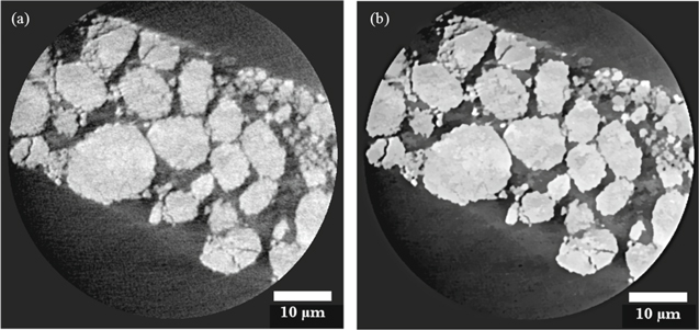
Figure 1. Orthogonal slices obtained using nano-scale CT of the failed cathode showing (a) unfiltered image and (b) image after applying a non-local means filter.
Download figure:
Standard image High-resolution image
Figure 2. Volume renderings of (a) bulk cathode structure, (b) segmented bulk cathode structure, and (c) individual cathode particles after label analysis.
Download figure:
Standard image High-resolution imageAll SEM micrographs are obtained from a Zeiss EVO 10 SEM, using the SE1 signal at 12 kV accelerating voltage with a magnification of approximately 5,000 yielding a pixel sizes ranging between 57–69 nm for all images.
Results and Discussion
Accelerated rate calorimetry was performed to initiate thermal runway in a commercial 18650 cell. The temperature profiles obtained for the cell are shown in Fig. 3. The initial exothermic event observed in Fig. 3a between 30 °C–50 °C is a result of the breakdown and reformation of the SEI layer,37 while the second visible exotherm at 175 °C indicates the onset of thermal runaway. It is possible that the discontinuity between the two exotherms is a result of the cell rupturing during failure, initiating the Joule-Thompson effect, as previously reported in literature.26 Further evaluation of the thermal failure process reveals the reaction rate of initial degradation and self-heating rate of thermal runway to be 7.82 × 10⁻³ min−1 and 8.5 × 10⁻² min−1, respectively. The plateau after the initial SEI layer exotherm observed in Fig. 3b, may be attributed to the shutdown separator incorporated into the cell design. The tri-layer composite nature of the polypropylene (PP) melting at approximately 135 °C and polyethylene (PE) at 165 °C, arranged as PP∣PE∣PP, is shown to have delayed the onset of thermal runway by approximately 1,750 min. This is outlined further in Fig. 3a, at 165 °C, where the separator melts and possible rupture of the cell may have occurred. It is considered that the thermal runaway is only delayed, in this case, due to the ARC operating in the heat-wait-search mode.38
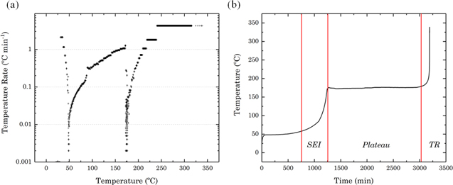
Figure 3. ARC self-heating rate profiles of a commercial 18650 cell. (a) The start temperature of 50 °C was increased step-wise by 5 °C. Onset temperature of 175 °C is shown. (b) Plateau in self-heating rate can be attributed to the shutdown separator.
Download figure:
Standard image High-resolution imageWhile the self-heating rate determined from this study reveals important information regarding heat dissipation within the cell, further studies are required to compare the influence of different cell chemistries26 and designs. A cylindrical cell with tightly wound layers (like an 18650 format) will have a different heat dissipation time-constant when compared to a pouch cell of equivalent capacity. Robinson et al. have previously reported a thermal runaway rate of 0.213 min−1 using ARC with similar parameters for a 2.5 Ah pouch cell.38
NMC is amongst the most widely used cathode materials to date, and its demand is projected to plateau until 2025.39 Results from this work correlate well with literature values for commercial 18650 cells with similar cathode chemistries and capacities.26 While these comparisons offer valuable insights into the thermal runaway process regarding the onset temperature, and rate of heat generation, the specific effects of whole cell structure and electrode morphology on this behaviour are not well understood. Understanding heat dissipation at the whole cell level as well as a component level are essential for accurately comparing the thermal runaway mechanism in commercial Li-ion batteries.
Macroscale X-ray CT results of the fully charged cell pre- and post-failure are shown in Fig. 4. The non-destructive nature of the technique enables visualisation of the architectural changes to the structure of the cell after failure. A 3D reconstruction of the cell prior to failure is presented in Fig. 4a; where orthogonal slices in the (X, Z) and (Y, Z) planes are also shown, similarly orthogonal slices of the failed cell are shown in Fig. 4b for comparison. Figure 4b shows the propagation of gas formation due to the decomposition of the SEI layer during failure. For example, Arrow 1, highlights possible delamination of an electrode layer where a gas pocket has formed.40 Arrows 2 and 3 show changes both to the outer casing of the cell as well as the arrangement of electrode layers. As the internal cell pressure increased, the ridge depicted by arrow 2, has expanded and changes to the tightly wound electrode layers are visible.

Figure 4. X-ray macro-CT results of a commercial 18650 cell (a) showing a 3D reconstruction of the whole cell and orthogonal slices in the XY and YZ planes before thermal runaway and (b) showing orthogonal slices in the XY and YZ planes after thermal runaway using ARC. Arrows depict areas of deformation within cell architecture.
Download figure:
Standard image High-resolution imageAt 130 °C, the positive electrode reacts with electrolyte and oxygen loss from the cathode is initiated. At temperatures above 200 °C thermal decomposition of the cathode occurs, where changes to the crystal structure begin and heat, in addition to CO2 and H2O are released.41 The effects of this phenomenon can be visualised in Fig. 4b where the active cathode material has delaminated from the aluminium current collector. Furthermore, changes to the outer casing, particularly at the positive terminal are shown, although there is expansion, there were no visible ruptures to the cell during post-failure analysis. Similarly, Finegan et al. reported that the cell casing and positive cap of a Li(Ni0.33Mn0.33Co0.33)O2 2.6 Ah 18650 cell at 100% SOC remained intact as it experienced thermal runaway.9 Although gas formation within the cell increases the internal pressure, it does not necessarily lead to cell rupture. In this case, the internal cell structure collapsed on itself as observed in Fig. 4b. A cylindrical mandrel at the centre of the electrode layers has been reported to play an important role in the mechanical failure of the cell; providing both mechanical strength and a route for gasses to reach the vent during failure.4
For microscale, pre- and post-failure analysis, the cells were disassembled and samples of the electrode layers were extracted as close to the centre of the cell as possible. The cathode of the failed cell was noted to be brittle with weak adhesion to the aluminium current collector, in contrast to the fresh cathode, but in a similar manner to that reported by both Finegan et al. & Robinson et al.10,38 The fresh and failed anodes on the other hand, were both relatively intact macroscopically. Figure 5 shows the SEM images obtained of the anode (a, b) and cathode (c, d) before and after failure. Changes to the anode surface are evident. Continuous exothermic decomposition and reformation of the SEI layer is believed to occur up to approximately 220 °C.42 Reaction products such as lithium-alkyl carbonates and lithium carbonate species make up the small precipitates of a surface film that are visible on the carbon particles. Exfoliation of the graphitic phase can also be seen. Although the particle size seems to have remained the same after failure, the porosity is observed to have reduced, in contrast to the observations by Robinson et al. in hard carbon electrodes in Na-ion batteries.38 SEM images of the cathode after failure show a rougher surface than compared to the fresh electrode; this could be attributed to the delamination and agglomeration of Co containing species as suggested by Finegan et al.10 Furthermore, it suggests that the temperature at the centre of the cell reached >350 °C. This cannot be seen in the ARC profile since the temperature is recorded by thermocouples attached to the outer casing of the cell only. While the electrode thickness remained the same after failure, particle sizes are visibly reduced in the volume reconstructions and PSD suggesting an increase in specific surface area and consequently a higher rate of heat generation.43
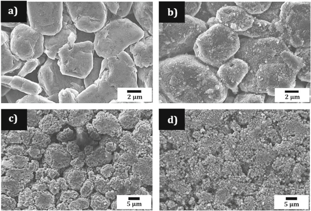
Figure 5. SEM images of (a) fresh, and (b) failed negative electrode from the commercial 18650 cell, (c) fresh, and (d) failed positive electrode after thermal runaway has occurred using ARC.
Download figure:
Standard image High-resolution imageThe onset temperature for oxygen evolution is highest for particles with smaller diameters.28 Under abusive conditions, the liberation of large amounts of oxygen is undesirable, therefore finding an optimum particle size distribution that minimises the cathode decomposition rate is critical. The cathode particles are expected to reduce both in mass and volume after undergoing thermal runaway.10 A PSD shown in Fig. 6, comparing tomography data of the fresh and failed cathode reveals there is a significant reduction in the mean diameter of the post-failure particles, approximately half their original size (from 9.6 to 6.5 μm). The sub-volumes used for the PSD of each sample were 86,132 μm3 and 41,612 μm3 for the fresh and failed samples, respectively. The spread of data for the post-failure particles differs greatly from the fresh sample. For example, there is a significant shift in the peak diameter from approximately 10 μm to 5 μm. Furthermore, the porosity of the failed sample was almost half of the fresh sample; i.e. 0.24 and 0.44, suggesting particle cracking and mass loss may have occurred. An evaluation of whether the considered sample volume fully encompasses all heterogeneities in the material is necessary.44,45 In this work, only a sample taken from the centre most point of the cell is analysed. Since it cannot be assumed that the cell reacts in a uniform way,9 comparing pre- and post-failure samples from separate points in the cell may give a more comprehensive understanding of electrode morphology changes. Furthermore, a representative volume element (RVE) analysis may be performed on the extracted sub-volumes to define the minimum volume which statistically represents the cathode material.46,47

Figure 6. Particle size distribution for particles from the fresh (top) and failed cell (bottom) with complementing XZ orthogonal slices obtained from X-ray micro-CT. For the PSD analysis a sub-volume was extracted from each electrode sample.
Download figure:
Standard image High-resolution imageThe links between cathode microstructure and thermal failure behaviour can be analysed further at finer lengths to accurately identify features which may not be visible at lower resolutions. In this study, X-ray nanoscale CT providing a pixel resolution of 63.1 nm, which enabled fine structural features to be seen. Micro-cracks and fractures within the failed cathode particles are shown in Figs. 7c–7d. Cracks in the particles increase the surface area available for reactions with the electrolyte during failure. Additionally, the presence of smaller cracked particles may result in a lower onset temperature29 and accelerated thermal runaway rate. The application of ARC in combination with X-ray CT imaging has been successfully demonstrated in this work. The "safety" and reliability of a commercial lithium ion battery has been characterised by determining the onset temperature and rate of heat generation. In addition, X-ray CT imaging at a nanoscale has revealed features such as particle cracks that could be useful for optimising electrode manufacturing processes for safer batteries with lower onset temperatures and heat generation rates.
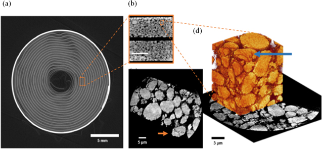
Figure 7. Multi-scale X-ray CT results of a commercial 18650 cell after thermal failure induced by ARC showing (a) an orthogonal slice in the XY plane where gas generation and delamination of the electrode layers is visible, (b) a microscale orthogonal slice of the failed cathode in the XZ plane, and (c) showing a nanoscale orthoslice of the failed cathode highlighting cracked particles with (d) showing a 3D reconstructed sub-volume.
Download figure:
Standard image High-resolution image
Conclusions
The thermal failure of a commercial Li-ion battery with an 18650 format was analysed across multiple length scales. ARC was used to induce thermal runaway and the temperature at which the SEI layer breakdown occurs (30 °C–50 °C) and the onset temperature (175 °C) was revealed. It was found that the melting of the shutdown separator significantly delayed the time taken to reach the onset temperature.
Pre- and post-failure examination of the cell using lab-based X-ray CT imaging revealed severe deformation of the electrode layers. Image analysis techniques applied to the bulk cathode both pre- and post-failure demonstrated that both the porosity of and PSD within the cathode nearly halved after failure. Nanoscale X-ray CT was more representative of the material showing evidence of particle cracking which is difficult to visualise in the SEM images of the cathode surface. Changes to the anode surface were also observed, suggesting its interaction with decomposed electrolyte may play a role in the thermal runaway process. In this work, electrode morphology has been considered when analysing battery failure behaviour. While it is suggested that larger particle sizes may increase the thermal stability, they can drastically reduce the overall power density of a battery.28 A critical balance between performance and safety exits, and future work considering electrochemical characteristics of a material alongside its contribution towards battery failure is imperative.
This work demonstrates how multi-length scale X-ray CT imaging can be used as a diagnostic tool to decipher the series of events that a Li-ion battery undergoes during failure. The investigation of various microstructural parameters of the cathode material and their possible influence on battery failure severity have been discussed.
Acknowledgments
This work was supported by the EPSRC (EP/N032888/1, EP/R020973/1, EP/K005030/1, EP/M028100/1), DP acknowledges funding from the EPSRC CASE Award scheme with Johnson Matthey, PRS acknowledges support from the Royal Academy of Engineering (CiET1718/59) and the Faraday Institution (Faraday.ac.uk; EP/S003053/1), grant number FIRG001.