
Abstract
The mechanisms of inhibition of chromate conversion coating on the filiform corrosion of coated aluminum alloy AA6016 was investigated using X-ray absorption near-edge structure (XANES) spectroscopy and Raman microspectroscopy. The results showed that Cr(VI) was preferably leached out at the opening of the filament, whereas Cr(VI) was reduced to Cr(III) at all other locations. The leached out Cr(VI) accumulated mainly in the pitting area, located in the scratch just outside the filament. The chromate released from the CCC was partly reduced to Cr(III) in the pit. The formation of an Al/Cr mixed oxide was observed in the pitting area. The repassivation of pits in the scratch by the chromate leaching from the CCC close to the scratch explains the low propagation of filiform corrosion observed for the chromated surfaces. © 2003 The Electrochemical Society. All rights reserved.
Export citation and abstract BibTeX RIS
Chromates are widely used as corrosion inhibitors and conversion coatings for a wide range of materials in different applications.1 Chromate conversion coatings (CCCs) are still commonly applied to improve the resistance to filiform corrosion of aluminum alloys used in the building, aerospace, packaging, and automotive industries.1 Chromates are, however, carcinogenic and pose a danger to health and the environment.2 Thus, there is a need to replace hexavalent chromium by more environmentally benign materials that provide a good corrosion protection for the final product, in view of concern over the environmental hazards presented by hexavalent chromium and expected legislation that will set low limits or prohibit the use of it. Other pretreatment methods such as anodizing are promising alternatives.3 4 However, many of these pretreatments are costly, and developers in the automotive industry are seeking alternative anticorrosion treatments that can be used on aluminum alloys. A deeper understanding of the mechanisms involved in the role of chromate in the inhibition of filiform corrosion is therefore of utmost importance for the development and production of new products that are more environmentally friendly than chromate.
Filiform corrosion of coated aluminum alloy is believed to occur as the result of a differential aeration cell or a differential oxygen concentration cell being formed. This cell produces a potential difference and thus anodic and cathodic sites are separated on the surface. Kaesche5 suggested one mechanism for the process, and Ruggeri and Beck6 subsequently provided experimental evidence for this mechanism. Kaesche5 suggested that the filament can be divided into a head and a tail, where the head acts as an electrochemical cell. Corrosion proceeds along a head that travels over the surface. This head has a leading edge and a trailing edge. As the head front is relatively deaerated, aluminum dissolves there and a primary anodic site is formed. The pH value in the head will be low as a consequence of aluminum cations formed in the anodic process being hydrolyzed. Oxygen will be reduced at the cathode, leading to hydroxide ions being formed at the trailing edge of the head. Recent Fourier transform infrared microspectroscopy and Kelvin probe measurements have confirmed this mechanism.7 Although progress has been made in the comprehension of the mechanisms of filiform corrosion, there are still gaps of knowledge. In particular, it is unclear how pretreatment with coatings such as CCCs inhibits the filiform corrosion of aluminum alloys.
The protective films formed by CCCs contain both Cr(III) and Cr(VI) species.8 The content of Cr(VI) in the CCC ranges from 15 to 27%.8 Several studies have shown that chromate retained in the CCC plays an important role in corrosion protection. In particular, the adsorption of Cr(VI) onto passive oxide films is important in the corrosion inhibition mechanism.9 Furthermore, CCC films are self-healing, and this property plays an important role in the behavior of these films. Zhao and co-workers showed using Raman spectroscopy that chromate is released from CCC films, migrates, and it then protects nearby uncoated areas.10 The concentration of chromate on nearby areas was approximately  M. Other studies using NaCl solutions or salt spray support these conclusions.8
11 However, no redeposition of chromium from CCC onto etched exposed aluminum surfaces was found in a recent study that used X-ray absorption near edge structure spectroscopy (XANES).12
M. Other studies using NaCl solutions or salt spray support these conclusions.8
11 However, no redeposition of chromium from CCC onto etched exposed aluminum surfaces was found in a recent study that used X-ray absorption near edge structure spectroscopy (XANES).12
XANES spectroscopy is a powerful technique for the in situ study of inhibiting species in passive films and in solution.13 14 The technique can be used to measure the concentration of metal ions in situ when metals dissolve. XANES can be used to determine the valence states of species present at very low concentrations (in the range of a few monolayers) in air, in an electrochemical cell, and even under highly resistive polymers. The technique has already been successfully used to study the action of corrosion inhibitors, such as solutions of chromate and cerium, on aluminum and aluminum alloys.13 14 XANES can be performed under ambient conditions, avoiding the risk of photoreduction of Cr(VI), which has been observed under the high vacuum used in X-ray photoelectron spectroscopy (XPS).15
The mechanisms of inhibition of chromate on the filiform corrosion of aluminum alloys have been studied using XANES in order to detect the valence state and the distributions of chromium species along a filament. Additional Raman spectroscopy investigations were used in order to monitor the transport of chromate from the CCC and to identify the ionic species in the pitting area at different stages of the process.
Experimental
Materials and exposure conditions
The experiments were carried out using commercially coated rolled AA6016 T4 aluminum alloy (composition by weight: 0.94% Si, 0.32% Fe, 0.07% Cu, 0.043% Mn, 0.44% Mg, remainder Al). The samples were pretreated by a conventional CCC (Alodine 1200) process, followed by a full paint covering (20 μm thick electrodeposited coating and a 100 μm thick top coating). Chomating was applied after degreasing and etching the aluminum, using Alodine 1200 (15 g L−1, pH 1.85, 30°C). The thickness of the CCC was approximately 1 μm, which corresponds to approximately 1 g m−2. A final coating of transparent polyurethane, 10 μm thick was applied to samples destined for XANES measurements. Some samples were treated by a chromium-free conversion coating process (e.g., tricationic phosphate and a commercial titanium-zirconium treatment) before being painted. The phosphate coating was applied using a commercial zinc phosphate solution  at 50°C, to obtain a phosphate layer
  of 2.6 g m−2. Some samples were treated with Ti-Zr in order to compare how different pretreatments inhibit filiform corrosion. This treatment was carried out at the premises of a chemical supplier. Two scratches forming an X were made to simulate a defect. The total scribe length was 7 cm and the scribe width was 0.5 mm. Filiform corrosion was initiated by contamination with sodium chloride followed by an exposure at a relative humidity of 85% and at two temperatures, 25 and 35°C.16 Three replicates of each pretreatment were tested. Samples of AA6016 covered by Alodine without any organic coating were used for Raman investigations. The CCC was carefully removed by fine grinding on a part of the sample. The corrosion was initiated by placing a droplet of 0.1 N HCl onto the bare metal, which was then exposed to humid air (95% relative humidity, RH) at room temperature (20°C).
XANES
XANES is characterized by two regions. Below a characteristic energy, the absorption edge, relatively few photons are absorbed. As the energy increases above the absorption edge, incident X-ray is strongly absorbed. The absorption edge corresponds to the excitation of a core electron from a bound state level to the continuum vacuum. The position of the edge shifts to higher energy as the valence of the Cr species increases.13 14 A distinct pre-edge peak is observed for Cr(VI) in tetrahedral coordination which is not observed for Cr(III) species. The XANES spectrum is a linear combination of spectra of Cr(III) and Cr(VI) components, and thus, the ratio of the intensity above the edge to the intensity below the edge provides an estimate of the Cr(VI) concentration.
Spectra were obtained near the Cr K absorption edge (5990 eV). The experiments were performed in air on beam X 26A (beam diam 15-35 μm) at the National Synchrotron Light Source of Brookhaven National Laboratory.
Raman microspectroscopy
Micro-Raman spectra were obtained with a LABRAM spectrometer from ISA-Jobin Yvon. The red line at 632.8 nm of a He-Ne laser with a constant power output of 9.7 mW was used. Neutral filters with optical densities of 1 or 2 were used when the product was unstable under the laser light. The laser power was chosen at a value that did not modify the spectra due to thermal effects. The area investigated was limited to 1.2 μm2 when using an 80 ULWD objective lens. A confocal microscope was used with hole diam fixed at 120 μm in order to separate contributions coming from the top and the bottom of the analyzed object. The resolution in depth was approximately 20 μm when the product was transparent to the excitation radiation.
Results
Performance of different chemical pretreatments
Figure 1 shows the area of underfilm corrosion following 6 weeks of exposure at 85% RH as a function of temperature for the different chemical pretreatments: chromating, phosphating, and Ti-Zr treatment. The length of the longest filament is given on top of the bars. The rate of propagation of filiform corrosion was lower for chromating than it was for the two other chemical pretreatments. Similar results were found independently of the temperature in the range from 25 to 35°C. This is consistent with a study performed by Wernick and co-workers,17 which showed that chromate films have a lifetime after salt spray exposure that is twice that of chromate-phosphate and phosphate films.
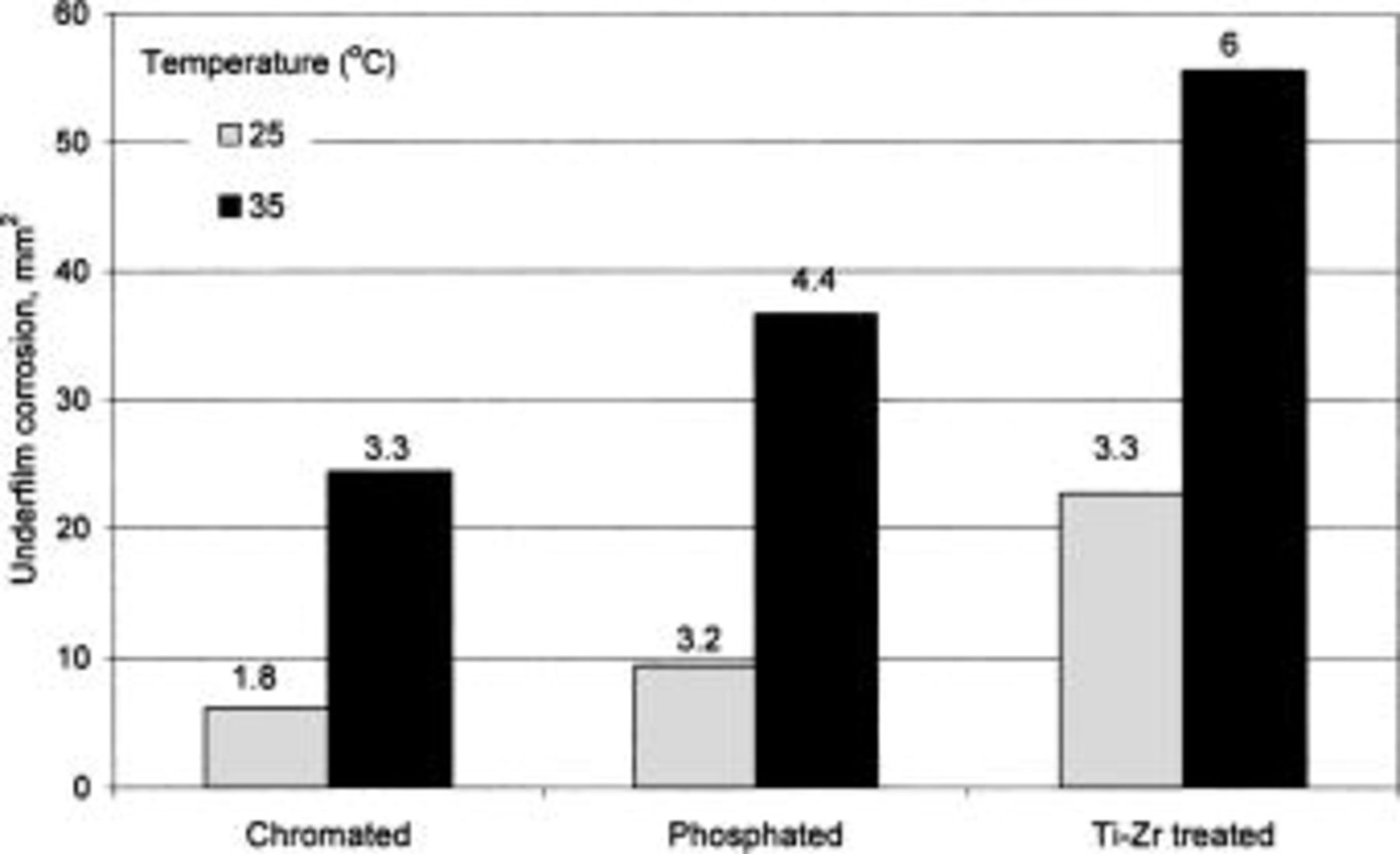
Figure 1. Underfilm corrosion on coated aluminum alloy AA6016 following different chemical pretreatments, after 6 weeks exposure at 85% RH at 25 or 35°C. The length of the longest filament (in mm) is given on top of the bars.
XANES measurements
Figure 2 shows a XANES spectrum for uncorroded AA6016 aluminum alloy covered with Alodine 1200. The spectrum was normalized with respect to the edge intensity. Thus, the intensity of the pre-edge peak at 5990 eV relative to the edge intensity indicates the fraction of Cr(VI) in the CCC. There was about 19% of Cr(VI) in the AA6016 samples treated with Alodine 1200. This agrees well with previous studies, which have found Cr(VI) content between 15 to 27%.8 Similar results to those shown in Fig. 2 were found below a 10 μm organic coating. The ratio between Cr(VI) to the total chromium in this case was 19%, which lies within the previous range, although the total signal was lower than that shown in Fig. 2. Filiform corrosion was then initiated according to the experimental procedure described above. Figure 3 is a laser scan micrograph of a filament formed on chromated AA6016 covered with a 10 μm polyurethane coating after 6 weeks exposure at 85% RH and 25°C. Figure 4 shows XANES maps at characteristic energies for Cr(VI) (Fig. 4a) and total Cr (Fig. 4b) over the filament shown in Fig. 3. The total amount of chromium decreased in regions close to the scratch and at some locations in the filament. Cr(VI) was more homogeneously depleted in the entire filaments, although some regions showed a higher decrease in the amount of Cr(VI). Both Cr(VI) and total Cr decreased to a great extent in the scratch (see Fig. 4c and d). This is shown more clearly in Fig. 5, which shows the ratio of Cr(VI) to total Cr in the filament (Fig. 5a) and in the scratch (Fig. 5b). Cr(VI) accumulated in the scratch close to the opening of the filament, whereas Cr(VI) was mainly depleted at the opening of the filament and at some locations along the filament. Hence, Fig. 5 shows that the change of Cr(VI) content was higher than the change in the total chromium content at specific locations in the filament. It is believed that these locations correspond to former heads of filament, which are known to act as pits.
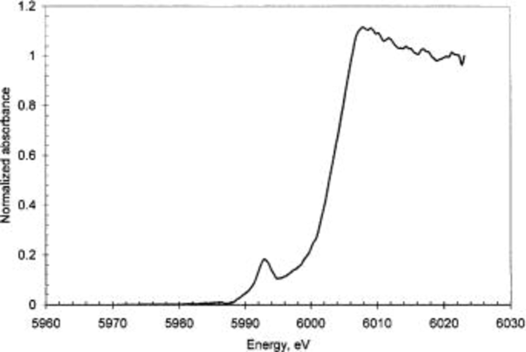
Figure 2. Energy scan over Alodine covering aluminum alloy AA6016.
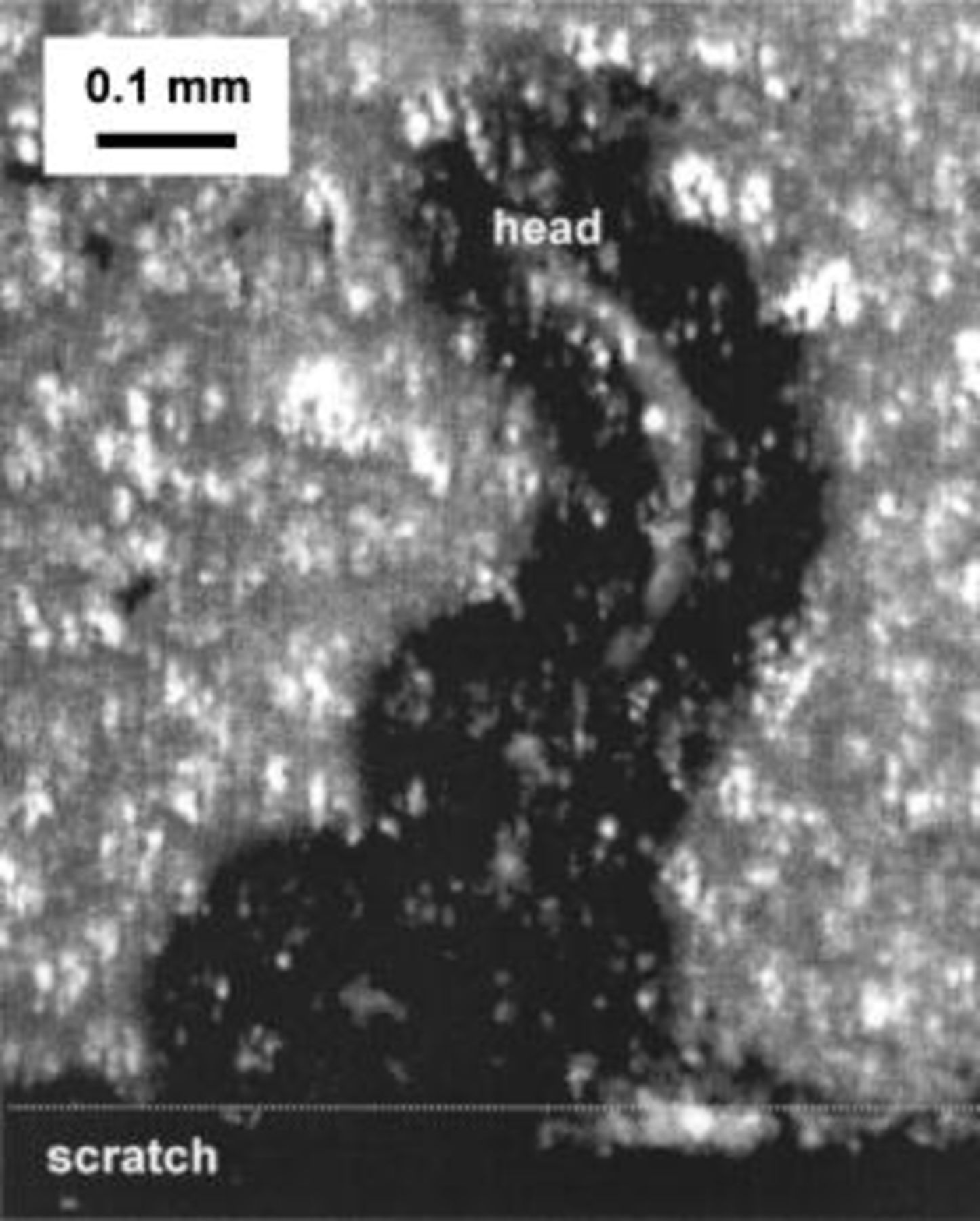
Figure 3. Micrograph of a filament formed on chromated AA6016 after 6 weeks of exposure at 85% RH and 25°C.
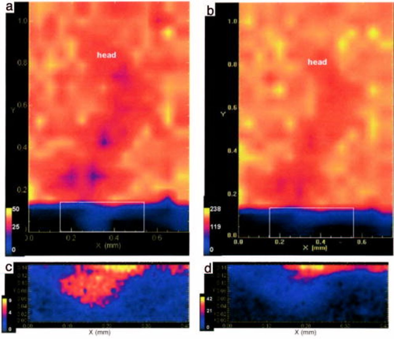
Figure 4. XANES maps obtained from Alodine 1200 coated AA6016 after 6 weeks of exposure at 85% RH and 25°C, over a filament (a) Cr(VI), (b) total Cr. And, over the scratch at the initial point of the filament as shown by the white square (c) Cr(VI), (d) total Cr.
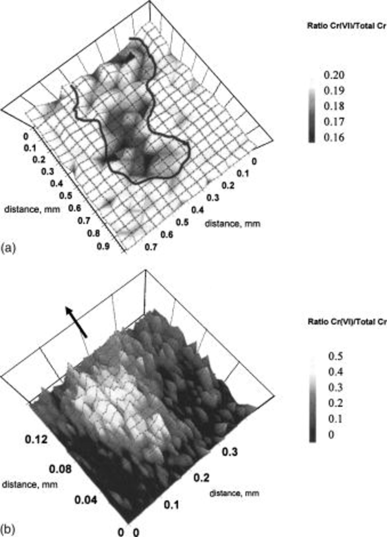
Figure 5. Ratio [Cr(VI)/Total Cr] map of (a) the filament and (b) the buildup of corrosion product in the scratch. The arrow indicates the location of the filament.
Comparing Fig. 4 and 5 shows that the amount of Cr(VI) decreased in the filament while the total amount of Cr remained almost unchanged. This indicates that Cr(VI) was reduced to Cr(III) in the CCC. Filiform corrosion is a dynamic process, and the active head moves continuously as long as the humidity is sufficiently high. Cr(VI) was not depleted at all (or only to a very small degree) at the current location of the head, which suggests that the corrosion inhibition of the anodic head was not completed when the measurements were performed. Cr(VI) was depleted and the total amount of Cr had decreased at the opening of the filament. Thus, it seems that Cr(VI) is preferentially leached at the opening of the filament. The chromate leached from the CCC then accumulated in the scratch, close to the opening of the filament. The location at which chromate accumulated was then the location of an early pitting attack. At these locations, an accumulation of aluminum corrosion products was observed. It should be noted that the areas of highest concentration of Cr(VI) correspond to the center of the pits (Fig. 4). The results clearly show that chromate is released from the CCC and migrates to the nearby uncoated scratch region. This agrees well with recent results obtained by Raman microspectroscopy.10
Raman microspectroscopy
Raman microspectroscopy is well adapted for the study of Cr(VI) compounds and this technique has been widely used to provide information on the structure of Cr(VI) species.18
19
20
21 Figure 6 shows the Raman spectrum of AA6016 treated with Alodine 1200. The spectrum has peaks of various widths, at ∼240, 500, 855, 1670, 2083, and 2130 cm−1. The peak at 855 cm−1 arose from the presence of Cr(VI), from the  symmetric stretching mode of Cr(VI)-O. The spectrum of CCC was similar to that of chromate
  in aqueous solution, which has a band at 840 cm−1.21
22 Previous studies on CCC using Raman spectroscopy have shown that this band is characteristic of chromate vibration in a polymeric mixed oxide Cr(III)-Cr(VI) that is present in Alodine CCCs.23 The broad bands centered at ∼500 and ∼240 cm−1 arose from the symmetric stretch and from the bending of Cr-O-Cr, respectively, suggesting that a dimeric
in aqueous solution, which has a band at 840 cm−1.21
22 Previous studies on CCC using Raman spectroscopy have shown that this band is characteristic of chromate vibration in a polymeric mixed oxide Cr(III)-Cr(VI) that is present in Alodine CCCs.23 The broad bands centered at ∼500 and ∼240 cm−1 arose from the symmetric stretch and from the bending of Cr-O-Cr, respectively, suggesting that a dimeric  species may be present.24 The bands at 2083 and 2130 cm−1 arose from CN vibration in FeCN from the treatment bath, while HOH bending appears around 1670 cm−1.23
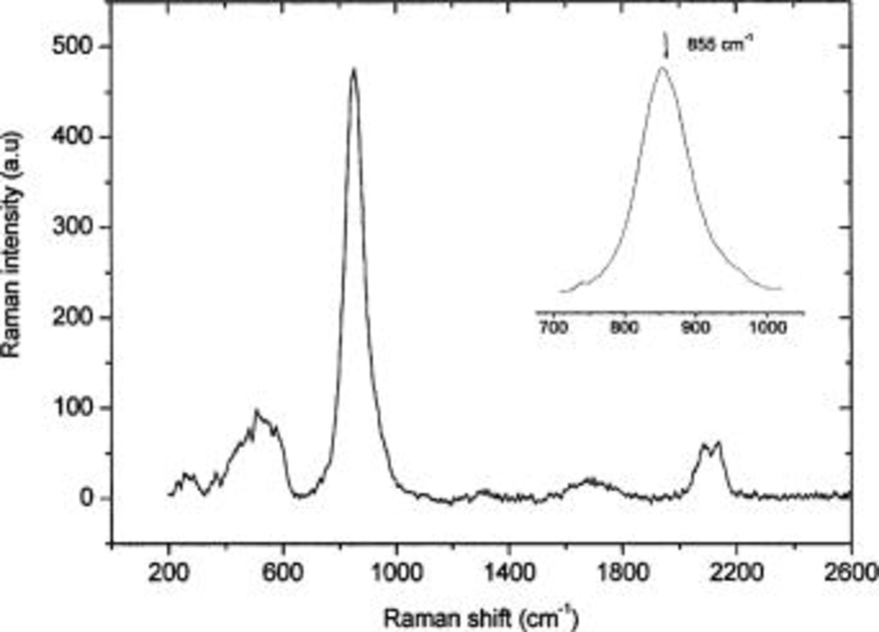
Figure 6. Raman spectrum of chromate conversion coating on AA6016.
Raman microspectroscopy was performed directly on the corrosion products after a droplet of aggressive solution (HCl, 0.1 N) was deposited inside the scratched area (the scratch penetrated down to metallic aluminum). Two cases were investigated: (i) the droplet of HCl extended onto the Alodine coating and  the droplet was not in contact with Alodine. HCl was carefully deposited onto the samples, and was left for 10 min in air. The samples were thereafter exposed to humid air (95% RH) at room temperature (20°C) for various times before Raman spectra were recorded.
In the first case, Alodine dissolved rapidly during the first hour of exposure to humid air. Spectrum a in Fig. 7 shows the Raman spectrum from such samples. It has a chromate peak at 850 cm−1, which is the same position as for Alodine, showing that chromate was present in the scratch. After three days in humid air, the corrosion layer became thicker due to the formation of a corrosion product, probably aluminum hydroxide gel that contained carbonate. The carbonate peaks at 1065 and 1100 cm−1 and the Al-O peak at 550-600 cm−1 support this conclusion (spectra b and c in Fig. 7).7 The relative intensity of the Cr(VI) peak in spectra from inside (spectrum b, near the metal surface) and outside the corrosion products (spectrum c, near the external surface) shows that the concentration of chromate was higher close to the metallic part. Furthermore, the widths and the positions of the bands were different than those of the peak recorded from Alodine (855 cm−1), as shown in the enlargement of this part of the spectra. The peak arising from inside the corroded layer can be deconvoluted into two peaks, one centerd at 840 cm−1 corresponding to free chromate and another at 870 cm−1 corresponding to the an aluminum/chromate compound during the corrosion process.19 The peak in the spectrum recorded outside the corroded layer was symmetric and centred at 860 cm−1, close to the value of peak recorded from Alodine.
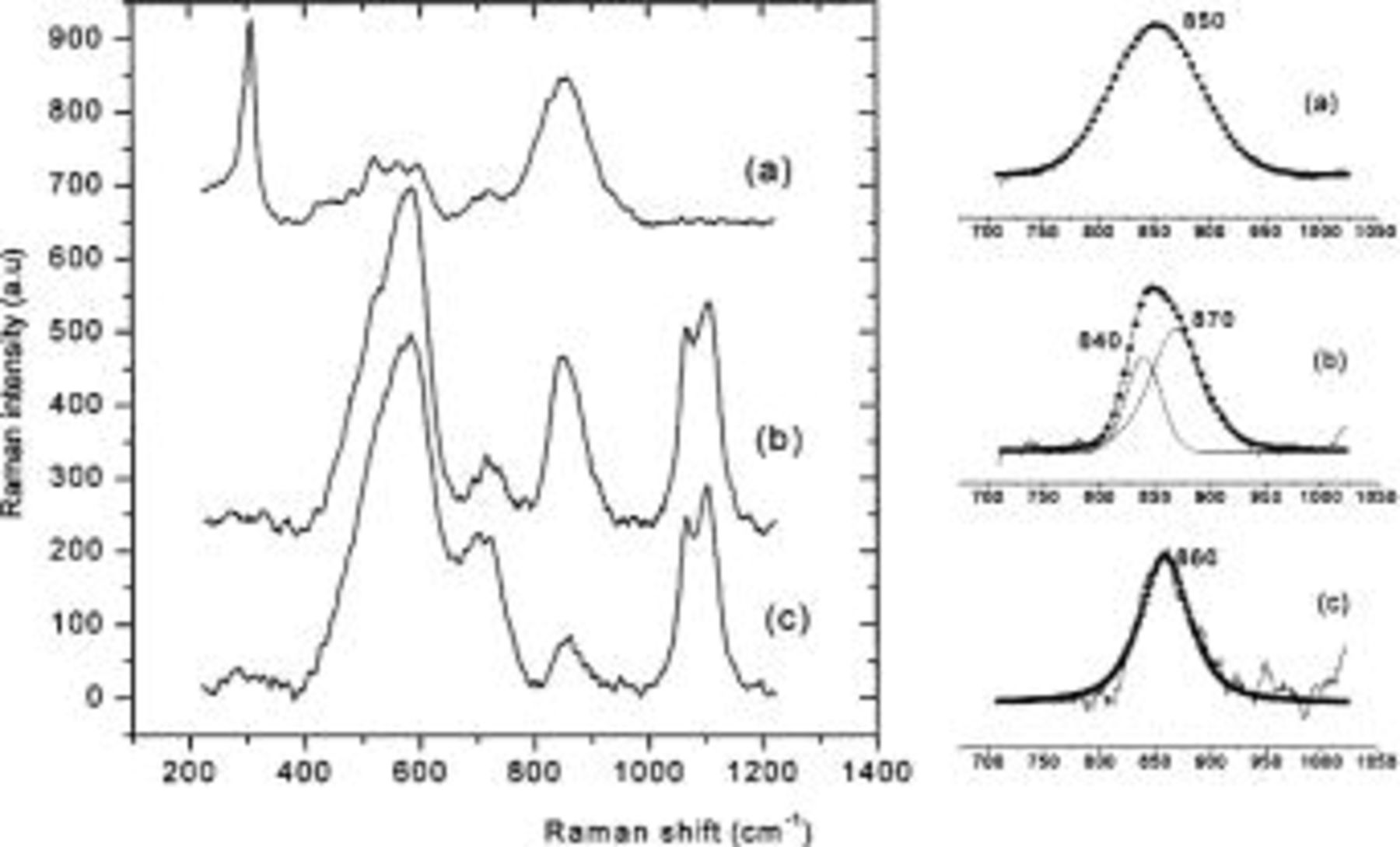
Figure 7. Raman spectra around a pit formed on AA6016. (a) on corrosion products after 1 h of exposure to humid air (95% RH, 20°C). (b) under the corrosion products, and (c) on top of the corrosion products, after 3 days of exposure in humid air (95% RH, 20°C). The corrosion was initiated in the scratch with a droplet of HCl (0.1 N) spreading over Alodine 1200 coating. Right side: deconvolution of chromate peak.
In the second case, in which there was no contact between HCl and Alodine 1200, pitting corrosion of aluminum resulted in the formation of an aluminum hydroxide containing carbonate, after 1 day of exposure. Raman bands attributed to the vibrations of Al-O in a tetrahedral environment and the vibrations of carbonate were clearly observed at 550-600 and 1065-1100 cm−1, respectively7 (see spectrum a, Fig. 8). The pit was located a few tens of micrometers from the CCC. It should be stressed that, an acidic salt layer of aluminum chloride and its hydrolysis products was formed during the first steps of pitting process.5 25 The initial salt layer incorporated carbonates during the growth of the pit, and was transformed into an aluminum hydroxide-containing carbonate. A mechanism of the propagation of filiform corrosion is detailed elsewhere.7 Chromate appeared in the corroded area after only three days of exposure to humid air. Note that Raman investigations were not performed at the exact center of the pit because the signal was disturbed by fluorescence coming from the thick layer of corrosion products. All measurements were recorded between the CCC and the center of the pit. The broad peak at approximately 850 cm−1 in the Raman spectrum from corrosion products close to the metal surface (spectrum b, Fig. 8) arose from chromate. The Raman peak was shifted to ∼900 cm−1 when the Raman laser was focused at the outermost layer of corrosion products (spectrum c, Fig. 8). These observations show that chromate species were released from the Alodine film and migrated towards corroded areas, where they reacted with aluminum corrosion products near the pitting place. It has been suggested that the increased concentration of chromate around a pit results in the formation of a Cr mixed oxide and/or an Al/Cr mixed oxide.10 The latter is more likely to form near the pit, because the formation of a Cr(VI)/Cr(III) mixed oxide is inhibited in the conditions in the pit.19
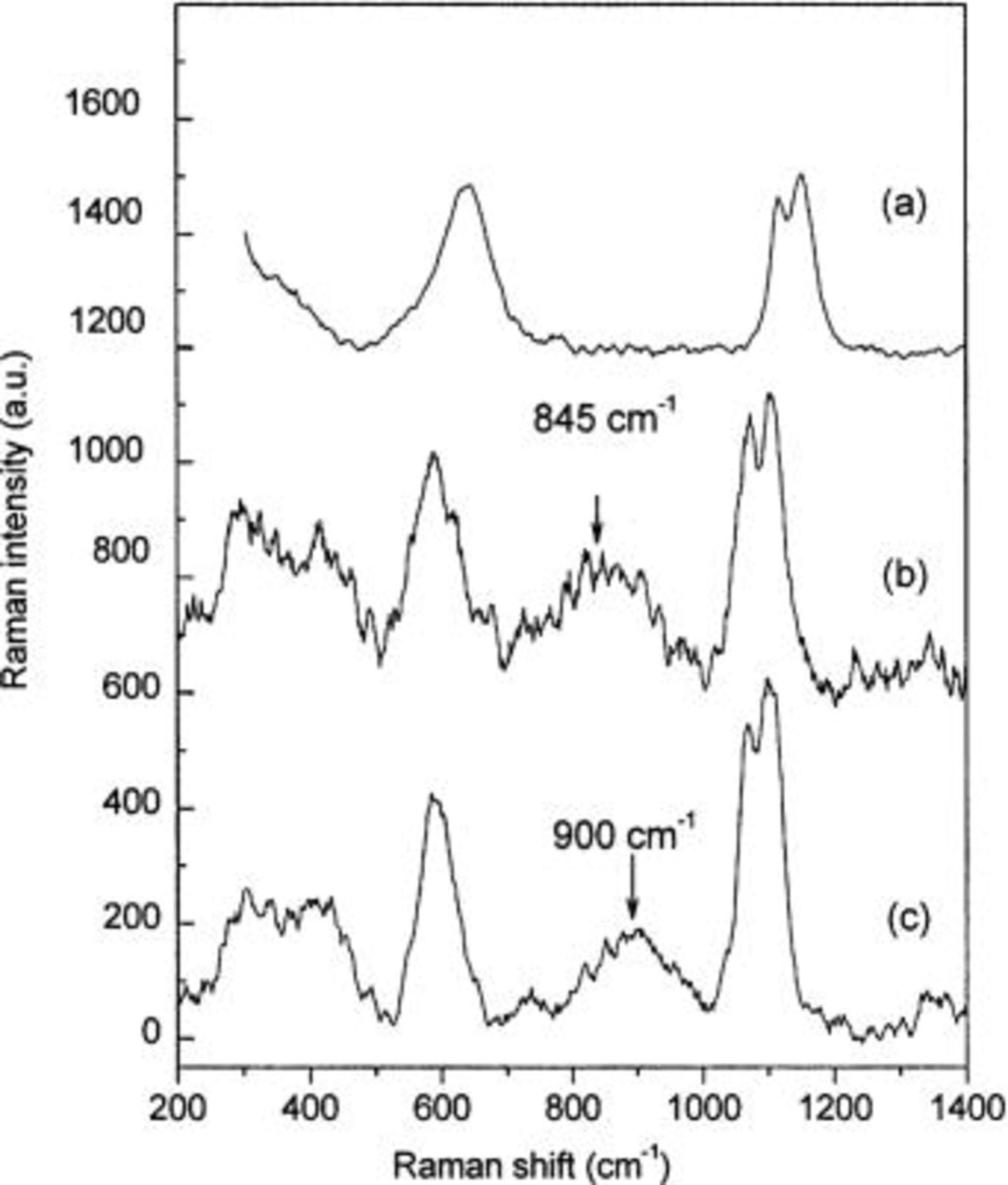
Figure 8. Raman spectra around a pit formed on AA6016. (a) after 1 day of exposure in humid air (95% RH, 25°C), (b) under the corrosion products, and (c) on top of the corrosion products after 3 days of exposure in humid air (95% RH, 20°C). The corrosion was initiated in the scratch with a droplet of HCl (0.1 N) without contact with the CCC.
Several explanations have been proposed for shifts of peak position of chromate toward higher wavenumbers. A shift has been observed when increasing chromium content and dehydratation of the chromate layer on chromium oxide supported by alumina, and this shift has been attributed to the formation of a polymeric chromate compound.20 A shift also occurs when passing from chromate (840 cm−1) to dichromate (910 cm−1) in aqueous solution.18 The equilibria of Cr(VI) species in solution depend on the pH:  (dichromate) and
  (bichromate) exist in acid media, whereas
  is the sole species at pH higher than 8. This leads us to expect that
  will predominate at the interface between the metal and the corrosion products, since the environment here is basic.
Discussion
Filiform corrosion is initiated at a defect when the oxide layer dissolves at some locations along the defect in the presence of chloride ions and water. This takes place, for example, at locations close to intermetallic particles that serve as local cathodes, or at grain boundaries. Aluminum dissolves close to the coating and this results in conditions that resemble the environment of growing pits being established. Aluminum chloride and hydrolysis products of aluminum salt solutions that are formed maintain a low pH.5 25 The conditions appear to be aggressive enough to weaken the adhesion of the coating and initiate filiform corrosion.26 Once initiated, the rate of filiform corrosion depends strongly on the chemical pretreatment of the aluminum and its ability to inhibit the corrosion process and to provide better coating adhesion. It has been shown in the present study, that CCC is highly effective in preventing filiform corrosion, while Cr-free alternatives such as tricationic phosphating and treatments based on titanium-zirconium do not protect as well. It should be noted that the mechanical pretreatment, the composition and surface microstructure of aluminum alloys, the organic coating, and the environmental parameters also determine the propagation rate of filiform corrosion.
Results from XANES and Raman spectroscopy show that Cr(VI) present in the CCC is released into the water layer and is transported to anodic sites in the scratched area by diffusion or migration. In our experimental conditions, the presence of Cr(VI) in the pitting area was detected about 3 days after the corrosion was initiated. It is likely that the release of Cr(VI) started earlier but the concentration was under the detectable level. Xia and co-workers have shown that the release and the adsorption of Cr(VI) depend on the pH, with the mixed oxide Cr(III)-Cr(VI) (or CCC) being more readily formed at low pH, and soluble Cr(VI) being more readily formed at high pH.9 The phase of Cr(VI) in solution may be 
 or
or  depending on the concentration and the pH. Raman spectroscopy after 3 days of exposure showed that a low concentration of Cr(VI); probably in the form of
  was released.
  is the main species in basic solutions above pH 8.27 This is consistent with the presence of cathodic sites near the pits where the pH is high due the reaction of oxygen reduction. The cathodic reaction is inhibited at these locations. This has been observed by McMurray and co-workers28 on filiform corrosion of AA2024 by scanning Kelvin probe measurement, and by Clark et al.29 Scanning Kelvin probe investigations on zinc in the presence of
  and NaCl have shown that the cathodic reaction is inhibited also in this case.30 The Cr(III) oxide film that is formed by the reduction of Cr(VI) inhibits reduction reactions such as the oxygen reduction reaction.31 The XANES investigation presented here showed that a mixture of Cr(VI)-Cr(III) was released from the CCC and incorporated into corrosion products at the opening of the filament in the pitting area. This shows that a part of Cr(VI) was reduced to Cr(III) in the pitting areas. It is, however, difficult to determine whether the Cr(VI) was released at anodic or cathodic sites, or both.
 ions subsequently approach the center of the pit and are acidified due to the low pH at these anodic sites.
  and/or the dimeric
  are in equilibrium in the range 6–2, and these two species are thus expected to form.27 The shift of the Raman peak arising from Cr(VI) toward higher wavenumbers is consistent with the transformation of chromate (840 cm−1) to dichromate (910 cm−1) in aqueous solution.18 The chromate peak also shifted after ageing of Al/Cr oxides in air for 3-4 days and after heating.23 This, however, cannot be the sole explanation. Indeed, such a shift also occurs on increasing the chromium content or the dehydration of
  supported on
  20 Chromate binds to
  to form Al/Cr(VI) mixed oxide. This could effect the corrosion protection in several ways, including surface charge neutralization, displacement of chloride ions, and an increase in local pH. The mixed oxide could also act as a reservoir for Cr(VI), releasing Cr(VI) into the solution.19
Pits subsequently repassivate, and this may explain why a so low propagation was observed on chromated AA6016 samples when the samples were exposed to humid air in presence of chloride. Cr(VI) is enriched mainly at a few locations in the scratch, and this also supports the proposed explanation for the low propagation rate. This agrees well with the XANES experiments, which showed that Cr(VI) was depleted in the CCC at the borderline to the scratch close to the initial pitting events.
Filiform corrosion was initiated as a result of two effects: aluminum oxide was dissolved along the scratch and, Cr(VI) was depleted along the scratch. However, the rate of propagation of filiform was reduced significantly when Cr(VI) was reduced to Cr(III) within the CCC. It is possible that chromate decreased the cathode/anode ratio in the filament and thereby decreased the rate of propagation of filiform corrosion. Scanning Kelvin probe experiments have shown that chromate strongly influences the potential in the tail of the filament, whereas the potential in the anodic part in the head is unaffected. This indicates that chromate mainly functions as a cathodic inhibitor during filiform corrosion.28
Conclusion
The mechanism by which chromate conversion coating inhibits filiform corrosion was investigated using XANES and Raman microspectroscopy. XANES experiments showed that Cr(VI) was depleted in the filiform filament close to the scratch and at locations of presumably former anodic sites. On the other hand, the content of total chromium and of Cr(VI) increased to a large degree in the scratch close to the opening of the filament. Cr(VI) was preferably leached out at the opening of the filament, whereas Cr(VI) was reduced to Cr(III) at all other locations. XANES and Raman microspectroscopy measurements showed that the leached out Cr(VI) accumulated mainly in the centers of pits, located in the scratch just outside the filament. The chromate released from the CCC was partly reduced to Cr(III) in the pitting area, where a mixure of Cr(III) and Cr(VI) was detected. Raman microspectroscopy measurements showed that an Al/Cr mixed oxide formed in the pit regions. Pits in the scratch subsequently repassivated by chromate leaching from the CCC close to the scratch, and this explains the low propagation rate of filiform corrosion observed on chromated aluminum surfaces.
Acknowledgments
We acknowledge the financial support of the Swedish Government and of our industrial partners: Pechiney, PSA, Renault SA, Sapa Technology, and Volvo Car Co. The authors thank Hugh Isaac from Brookhaven National Laboratory and are grateful for the assistance of NSLS beamtime X26A personnel.
Korrosioninstitutet assisted in meeting the publication costs of this article.