Abstract
The quality of the semiconductor–barrier interface plays a pivotal role in the demonstration of high quality reproducible quantum dots for quantum information processing. In this work, we have measured SiMOSFET Hall bars on undoped Si substrates in order to investigate the device quality. For devices fabricated in a full complementary metal oxide semiconductor (CMOS) process and of very thin oxide below a thickness of 10 nm, we report a record mobility of 17.5 × 103 cm2 V−1 s−1 indicating a high quality interface, suitable for future qubit applications. We also study the influence of gate materials on the mobilities and discuss the underlying mechanisms, giving insight into further material optimization for large scale quantum processors.
Export citation and abstract BibTeX RIS

Original content from this work may be used under the terms of the Creative Commons Attribution 4.0 licence. Any further distribution of this work must maintain attribution to the author(s) and the title of the work, journal citation and DOI.
The spin of an electron in silicon has been considered as one of the most promising candidates for large-scale quantum computers, due to its long coherence time, compactness, potential to operate at relatively high temperatures, and compatibility with complementary metal oxide semiconductor (CMOS) technology for upscaling [1–3]. High fidelity single and two qubit operations have been demonstrated in academic lab-based devices [4, 5]. The scale up process to multi-qubit arrays will however entail high quality qubits in large numbers, necessitating a transition to industrial fabrication techniques [6].
While spin qubit-devices can be fabricated using semiconductor manufacturing techniques, a detailed and careful analysis on the impact of different fabrication process steps on the performance of spin qubits is crucial. Hallbar mobility is a widely used metric to characterize the MOS interface quality, which can provide valuable feedback to fabrication process optimization. In this work, we perform transport measurements on SiMOSFETs and investigate the quantum Hall effect. The gate stack for SiMOSFET is the same as that for qubit integration [7]. We extract key characteristics of the MOS gate stack such as critical density and mobility as well as transport and quantum lifetimes. Comparing the obtained results to a transport model, we identify and quantify the leading scattering terms. Additionally, we explore possible mobility limiting factors when changing the top gate material from polySi to titanium nitride (TiN).
The devices measured in this work are undoped inversion gated Hall bars fabricated in a state-of-the art 300 mm fab line [7]. The starting substrate consists of a (100) silicon wafer with a background doping <5 × 1015 cm−3. The Hall bar top gates are defined by electron beam lithography and subsequent dry etching process, and the fanout metal pins are defined by deep UV lithography. After depositing the gate material, the whole wafer is covered with a passivation layer. In order to measure the electronic properties of the investigated samples, a positive voltage has been applied to the top gate to form a two-dimensional electron gas (2DEG) at the interface of Si and SiO2. Throughout this work, we perform four-wire electronic transport measurements using standard lock-in techniques. Both the longitudinal and transverse Hall voltages were measured simultaneously with differential voltage amplifiers. Additionally, the current through the sample was measured using an IV transimpedance amplifier. The measurements were carried out in a dilution refrigerator with a base temperature of 20 mK with a 9 T magnet. Higher temperatures were achieved by heating the mixing chamber, resulting in electron temperatures between 100 mK and 4.2 K.
Figure 1 shows the density and mobility study performed on a sample with a polySi top gate at three different temperatures and on four different samples across the wafer. First, the density of charge carriers in the 2DEG was extracted from the transverse Hall effect in the linear regime far from quantum oscillations, particularly at the lowest temperature with magnetic field between ±1 T. The density of charge carriers in the 2DEG has an overall linear dependence on the applied top gate voltage VG as expected from a plate-capacitor model. Assuming the relative dielectric constant Figure 1. Density and mobility study. (a) Linear relationship between 2DEG sheet density nS and the top gate voltage VG. Below a top gate voltage of ≈0.4 V the extracted density deviates from the expected linear behaviour as shown in the inset. (b) Channel mobility μ measured as a function of nS and corresponding fit to a mobility model (black) which includes scattering from charge impurities and surface roughness. The inset shows a SEM image of a similar device as the one used during the experiments with the same dimensions. (c) Channel mobility μ trends with respect to temperature at various sheet densities. The symbols coincide with the ones used in panel (b). The dashed lines are linear fits to the extracted mobilities and appear curved due to the logarithmic scale. (d) Longitudinal conductivity σxx
in the low density range and fit to a percolation theory (black). A linear trend with respect to temperature for np is observed in the inset. Download figure: r(SiO2) = 3.9, we extract the thickness of the oxide and obtain a value of 8.1 ± 0.1 nm. This in good agreement with the oxide thickness of 8 nm defined during the fabrication process. As one can see in the inset of figure 1(a), the extracted density deviates from a linear regime at very low VG near the threshold voltage, particularly at the lowest temperature. A temperature dependent dielectric constant would result in a temperature dependent slope of the nS regardless of the VG [8], which is not observed in this study. Partial localization of charge carriers in the disorder potential at low sheet density, on the other hand, could explain this [9]. Here, the disorder potential is mainly due to bulk charge scattering and scattering from oxide charges. At these rather low densities close to the 2D metal to insulator transition (MIT), partial localization would effectively reduce the sheet density of mobile carriers below a simple capacitor model, as observed, and thus slightly enhance the mobility, which is inversely proportional to the density.
The extracted densities, in combination with the sheet conductance from the longitudinal voltage measurements, allow for the calculation of the mobility μ at various temperatures. The resulting curves are shown in figure 1(b). We measured a maximum mobility of 17.5 × 103 cm2 V−1 s−1, the highest mobility reported for SiMOSFET devices with sub 10 nm oxide thickness [10–12] corresponding to a mean free path of 160 nm. The mobility is consistent in the four Hallbars measured across the wafer. Of course, we note that without the restriction of oxide thickness, much higher mobilities have been reported [13, 14]. We fit the mobility curve with the Kruithof–Klapwijk–Bakker (KKB) model (reference [15]) which includes remote impurity scattering and surface roughness terms [15, 16]. Solving the model self-consistently for three separate temperatures (0.5, 0.9 and 4.2 K) yields the charged impurity center density NC = 1.53 ± 0.03 × 1010 cm−2, the rms height of the amplitude of the interface roughness Δ = 5.9 ± 0.51 Å and the correlation length L = 1.8 ± 0.35 nm. The parameters extracted from the KKB model compared to other experimental studies [12, 17, 18] indicate a slightly lower charged impurity density and a larger correlation length resulting in an overall improved mobility. Lower charged impurities and a smoother interface are critical for future qubit implementations.
As shown in figure 1(b), there is a slight deviation of the maximum mobility from the theory curve at 0.9 K, and the theoretical curve does not agree with the reported data for 0.1 K in the low density regime. This could be explained by the assumption of a linear relationship between mobility and temperature in the KKB theory. According to our fitting, this assumption seems to be only valid above 1 K and can become a more complex function of temperature below 1 K if the low density regime becomes non-linear. This is due to the fact that the slightly reduced density (compared to the capacitor model) results in a slightly higher mobility, explaining the deviation of our data from the theory. Furthermore, for sheet densities nS close to the depletion charge density ndep, the calculation of the finite extent of the wave function in the KKB theory can become unreliable because of the assumed approximations. While the density in our sample is approaching a localized regime, the reported maximum mobility is at a sheet density 0.5 × 1011 cm−2 which corresponds to a top gate voltage of 0.4 V. At this voltage the deviation of the sheet density from the linear capacitor model is not significant (roughly 8%). The effect on the mobility is also insignificant as is confirmed when the mobility is calculated using a linearly extrapolated density (figure A1). The theoretically predicted curve can be recovered by using a linearly extrapolated density during the calculation of the mobility. Further details are discussed in appendix
Another key parameter is the percolation density, which indicates the minimum density required to form a conducting channel. Generally, the percolation density describes the disorder in the channel at low densities, where quantum devices typically operate. In figure 1(d), we employed a MIT model in order to fit the density-dependent conductivity  [17], where np and p are the percolation density and universal exponent, respectively. However, this model is only valid in the low density regime and deviates above n = 8 × 1011 cm−2. We fixed the exponent p = 1.31, as expected in a two-dimensional system, and allowed np to vary [17]. Our fits yield np = 1.86 × 1011 cm−2 at T = 4.2 K. As seen in the inset of 1(d) the extracted np decreases with decreasing temperature, which is in agreement with previous studies [17], and is below 1 × 1011 cm−2 at the lowest temperature. Such a low percolation density is among the lowest reported for similar devices [12, 18].
Additionally, we investigate the temperature dependence of mobility at various top gate voltages. For sheet densities less than 2 × 1012 cm−2 the mobility is a function of temperature, with a linear dependence for temperatures above 1 K (see figure 1(c)). The temperature dependence of the mobility is only visible for low electron densities because mobilities at higher densities are limited by surface roughness, which is not temperature dependent. Additionally, the peak mobility shifts to higher densities at higher temperatures due to the activation of background charges limiting the mobility at high temperatures.
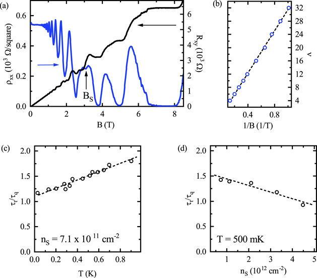
In order to extract more information about the transport properties and the dominating scattering mechanism, we investigated the transverse resistance Rxy
and longitudinal resistivity ρxx
in the quantum Hall regime. The magnetic field B was swept up to 8.5 T at a fixed sheet density of 7.1 × 1011 cm−2 near the peak mobility. As shown in figure 2(a), we observe Shubnikov–De Haas (SdH) oscillations starting at 0.8 T and begin to resolve spin splitting at 3.2 T. The ρxx
shows well developed zeros for magnetic fields larger than 3.8 T. In combination with the single frequency of the SdH oscillations extracted below 2.5 T and the absence of beatings strongly indicate single subband occupancy. We further observe a four-fold degeneracy in the filling factor which changes to a two-fold degeneracy as we increased the magnetic field (figure 2(b)). The remaining two-fold degeneracy is due to the two lowest lying valleys which are split off from the remaining four valleys due to the z-confinement in silicon (100) [19]. A linear fit of the filling factor (figure 2(b)) with respect to inverse magnetic field yields a sheet density 7.1 × 1011 cm−2 in agreement with the extracted Hall density, further confirming clean single subband transport in the investigated samples. Figure 2. Extended Hall studies with transport properties. (a) Longitudinal resistivity ρxx
(blue) and transverse resistance Rxy
(black) at nS = 7.1 × 1011 cm−2 as a function of magnetic field B. The arrow indicates the magnetic field spin is resolved. (b) Linear relationship between filling factor ν (blue scatter) and inverse magnetic field. The solid line is a fit from which the sheet density is calculated. (c) and (d) Extracted dingle ratio τt/τq as a function of temperature T and sheet density nS, respectively. The dingle ratio is slightly temperature and density dependent and is Download figure: , which indicates that large angle scattering is most dominant scattering mechanism in this sample.
Upon further investigations into the SdH oscillation amplitudes below 2.5 T, we were able to extract an effective mass m* = 0.21 ± 0.02 ⋅ m0 from the temperature dependent data, which corresponds to the transverse mass expected for silicon samples with similar background doping [20]. Further details are discussed in appendix  to
to  with increasing temperature, indicating a shift in the type of scattering dominating at different temperature ranges. We can see an inverted trend for the Dingle ratio with respect to density. For a fixed temperature of 0.5 K, we observe a decrease from a ratio of
  to
to  by increasing the density, again showing a slight shift towards large angle scattering. This is true for all measured temperatures and densities. In all, the observed Dingle ratio around 1 to 2 shows that short range/large angle scattering is the dominant scattering mechanism in this system, where the scattering centers are near or in the channel itself [20].
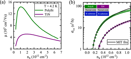
Furthermore, we investigate the effect of two different gate metals on the mobility and percolation density. We chose polySi and TiN as top gate materials since both are widely applied gating materials for integrated CMOS device fabrication. While polySi has generally larger mobilities, which indicates a small disorder potential and therefore a low dot-to-dot variation, TiN exhibits low resistivity and is superconducting at low temperatures, which is desirable for microwave qubit control and readout. The density dependent mobilities at 4.2 K, for both TiN and polySi are shown in figure 3(a). There is a decrease by a factor of three in the maximum mobility when changing the material from polySi to TiN while all other parameters in the fabrication remain the same. We expect the TiN gate to be superconducting at these temperatures and for fields lower than ∼3.3 T. However, the decrease in the mobility cannot be attributed to the modification of the magnetic flux in the 2DEG due to the Meissner effect. The deposited TiN gate thickness is less than the London penetration depth λL, and additionally there are no discontinuities during the magnetic field sweep indicating no superconducting transition. To investigate the underlying mechanism for the mobility difference, we perform high magnetic field Hall measurements on the TiN devices as well. Unlike polySi which shows vanishing ρxx
in figure 2(a), ρxx
of TiN does not have well developed zeros. This can be attributed to the lower mobility and could be due to multiple subband transport [21] (see appendix Figure 3. Gate material study. (a) The channel mobility μ with respect to sheet density nS for polySi (green) and TiN (violet), both at 4.2 K. The mobility shows a decrease by a factor of three when changing the top gate material from polySi to TiN. (b) Longitudinal conductivity σxx
with respect to sheet density. The fits to percolation theory (black) show a significant difference between the polySi and TiN percolation densities. Download figure:
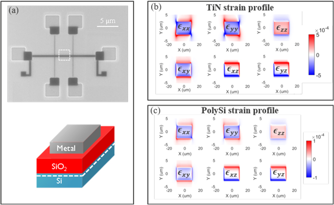
To explain the inter-subband scattering, we firstly consider the effect of strain. On silicon (100) surfaces, materials used as top gates with certain coefficient of thermal expansion (CTE) introduce compressive strain [22]. This leads to a decrease in the energy splitting of two subsequent subbands [20, 23, 24]. Strain simulations, described in appendix
In summary, we have characterized SiMOSFET samples using Hall effect measurements. We found a record mobility of 17.5 × 103 cm2 V−1 s−1 which is the highest reported mobility to date for SiMOSFET samples with sub-10 nm oxide thickness. Further, we have shown that the dominant mobility limiting factor are charges near the conducting channel, which can be improved by further reducing the impurity levels in the substrate. For example, an epitaxial layer can reach a background doping level of roughly 1 × 1012 cm−3, which is three orders of magnitude lower than the samples measured in this study. Additionally, we show that the choice of top gate material directly affects the mobility and percolation density. Factors such as strain and oxygen scavenging could explain the strong influence on both parameters. This demonstrates that the choice of top gate material is of paramount importance. The MOS interface has been widely identified as the source for charge noise and disorder sites, which limits the qubit performance and upscaling.
Further improvements in mobility can be achieved by reducing charged impurity density or step height. This can be realised by additional forming gas anneals [18] or growing epitaxial pure silicon on the standard substrate. While increasing the correlation length increases high density mobility and improves device uniformity over large scale qubit arrays. Furthermore, to improve the qubit device fabrication, more systematical investigations are needed. The Hallbar mobility and the analysis presented in this study could provide valuable insight into the gate stack over a large device area and direct further fabrication optimizations, which could pave the way for a large scale spin qubit processor integration with a full CMOS process. Spin qubits in silicon MOS structures are designed to have an effective dot diameter of roughly 10 nm. Considering spin qubits being operated in the last electron regime, we use the percolation density to estimate an approximate distance between scattering centers  35 nm. This would, statistically, correspond to one out of every three dots having an impurity within its diameter. These estimations further highlight the importance of improving both the mobility and percolation density for spin qubit applications.
Acknowledgments
This work was performed as part of IMEC's Industrial Affiliation Program (IIAP) on Quantum Computing. Additionally, this work was supported by the Swiss Nanoscience Institute (SNI), the Swiss National Science Foundation (SNF), the National Centers of Competence in Research (NCCR) SPIN and the EU H2020 European Microkelvin Platform (EMP) Grant No. 824109.
Author contributions
TNC, AE and DMZ performed the experiments, analysed the measurements and wrote the manuscript with input from all authors. BG designed the test structures. SK and JJ fabricated the devices. FAM performed the strain simulations. The work was completed with assistance from RL, PVD and IR.
Data availability statement
The data that support the findings of this study are openly available at the zenodo repository at DOI https://doi.org/10.5281/zenodo.5762556.
Appendix A.: Mobility as a function of linear density and MIT fitting range
During the calculation of the mobility at the lowest temperature, we observed a peak mobility higher than the KKB model (see figure 1(b)). We associated this deviation to the non-linear density dependence in the small top gate voltage regime at the lowest temperature as shown in the inset of figure 1(a). This assumption is further supported because the theoretical curve can be recovered using a linear extrapolated density when calculating the mobility (see figure A1). This behaviour can be explained within the KKB theory, where the depletion charge density ndep is implicitly assumed to be significantly smaller than the sheet density nS especially in the critical regime of maximum mobility [15]. If the density becomes non-linear, this violation of the linear density assumption has a significant impact when calculating the finite extent of the wave function b within the Coulomb scattering term ⟨|UC(q)|2⟩ and the dielectric response function ɛ. Further research in this regime is needed in order to capture the behaviour found in this work, but it exceeds the scope of this work. Nevertheless, we emphasize the mobility of 17.5 × 103 cm2 V−1 s−1 is the properly measured mobility, and the slightly lower peak mobility of 16.5 × 103 cm2 V−1 s−1 in figure A1 is a modelled mobility assuming a linear density model. The previous mobility record was ≈10 × 103 cm2 V−1 s−1 for a comparable sample although the oxide was slightly thicker in that work [12].
Figure A1. Mobility as a function of linear density and MIT fitting range. (a) When using a linearly extrapolated (instead of the carefully extracted) density in order to calculate the mobility of our sample (blue), the peak mobility becomes slightly smaller than previously demonstrated in figure 1(b). Additionally, we can fit the KKB theory (black) self-consistently with the other temperature data highlighting the importance of the density values. (b) By varying ΔnS for extracting the percolation density np within the MIT model, we determine the optimal fitting range. We chose ΔnS = 3.2 × 1011 cm−2 (indicated by the red box) because the extracted np does not change significantly while changing ΔnS. Download figure:
The MIT model we used in this work is only valid at very low densities (below 1 × 1012 cm−2) and therefore is rather sensitive to the fitting range. In order to find the appropriate fitting range, we varied both the minimum and maximum value independently. As shown in figure A1, we determined that fitting the data between 2.7 × 1011 cm−2 and 6.0 × 1011 cm−2 yields the most reliable outcome because variations in the fitting range do not significantly change the result.
Appendix B.: Extraction of m* and τq
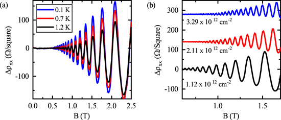
In order validate our evaluation approach and our experiments, we extract the effective mass from the temperature dependence of the SdH oscillations as seen in figure B1. For that, we subtract a polynominal background from the ρxx data and use the following formula as described in [27, 28]

with χ(T) = 2π2 kB T/ℏωc and ωc = eB/m*. Here, T is the temperature, T0 the lowest temperature, kB is the Boltzmann constant, ℏ the reduced Plank constant, e the electric charge, B the magnetic field and m* the effective mass. Using the effective mass as the only free fit parameter, we extracted m* = 0.21 ± 0.02 ⋅ m0, which is close to the expected value of m* = 0.19 ⋅ me.
Figure B1. SdH oscillations. (a) We can extract the effective mass by analysing the temperature dependent SdH oscillations at various magnetic field values B. (b) The envelope of the SdH oscillations in the fully spin and valley degenerate regime ( Download figure: 2.5 T) we can extract the quantum lifetime τq for various densities. Curves are offset for clarity.
Further, the envelope of the SdH oscillations allows for the extraction of the quantum lifetime τq. For that, we use the following formula

Therefore, by analysing the slope of the magnetic field dependent logarithmic term we can extract τq for all measured densities and temperatures. In combination with the transport lifetime τt we can then further extract the dingle ratio as described in the main text.
Appendix C.: TiN data at high fields
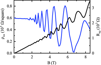
In comparison to the reported data in figure 2(a), TiN does not show well developed zeroes in the longitudinal resistivity ρxx at high magnetic fields at a temperature of 500 mK (see figure C1), as expected for a much lower mobility. Further, the transversal Hall resistance Rxy shows oscillating features instead of the expected Hall plateaus. This could be due to multiple subbands contributing to the overall transport or with the increased density of background charges due to the above mentioned oxygen scavenging.
Figure C1. TiN data at high fields. Longitudinal resistivity ρxx
(blue) and transverse Hall resistance Rxy
(black) of the sample measured with a TiN top gate at 500 mK. Both the not well developed zeroes in ρxx
and the oscillating Rxy
indicate multiple subband occupancy. Download figure:
Appendix D.: Strain simulations
We quantify the stain induced in the 2DEG due to the different thermal expansion coefficients of both gate materials. The strain was simulated using a commercially available software [29]. The silicon was simulated isotropically. The temperature dependence of the CTE for polySi up to room temperature is assumed to be linear because there is no reported data above 200 K [30]. Further, we neglect the intrinsic strain induced during the fabrication process, which is beyond the scope of this work. Thermal contraction is considered from room temperature down to the cryogenic measurement temperatures. All simulations were performed in three dimensions and the components of strain  x
,
x
,  y
,
y
,  z
are calculated 5 nm below the oxide due to the finite extension of the wavefunction. As shown in figures D1(b) and (c), there is a large difference in strain between TiN and polySi. While TiN induces strain up to 2.4 × 10⁻⁴, polySi induces significantly less strain of approximately only 0.28 × 10⁻⁴.
Figure D1. Gate material strain simulations. (a) Schematic of the Hall bar used for the strain simulation. The strain in the channel was calculated using sprocess in the region indicated by the dashed white line. (b) and (c) The strain in the channel for the polySi and TiN respectively. The model uses literature values for the thermal expansion coefficient for both materials. Download figure:


