

Abstract
In this short paper, the hyperbola-based analysis of wave interference recently developed by Thomas is employed to study the pattern of concentric circular fringes captured on a distant screen, when its plane is oriented orthogonal to the line joining two coherent point-sources. Newton's rings are another instance of concentric circular fringes, generated with an extended source and a plano-convex lens-glass plate combination. The underlying geometry of the latter scenario, as described in the literature, allows for the estimation of two important physical parameters viz. the wavelength of light and the refractive index of a liquid medium. It is demonstrated here that the geometrical arrangement of the former scenario can in principle, be utilized to reach the same ends as well. Additionally, the hallmark distinguishing features of both types of circular fringe patterns are qualitatively and quantitatively elucidated.
Export citation and abstract BibTeX RIS

Original content from this work may be used under the terms of the Creative Commons Attribution 4.0 licence. Any further distribution of this work must maintain attribution to the author(s) and the title of the work, journal citation and DOI.
1. Background and motivation
In some recently published papers on the classical double slit experiment, a hyperbola theorem was used to describe the distribution of interference fringes on distant screens of varied shapes [1, 2]. In this treatment, the slits were assumed to have negligible widths and idealized to behave as coherent point sources. The wavefronts that emanate from them at a steady frequency and in-phase manner, interfere with each other either constructively or destructively to form an alternating series of bright and dark fringes that can be captured on a detection screen placed some distance away. The shape of these fringes depends on the orientation of the screen relative to the line joining the two point-sources [3, 4]. When the plane of the screen is placed parallel to the line joining the two sources, the fringes are hyperbolic and when placed perpendicular, they are circular [5, 6]. In the former case, the fringes appear straight if the eccentricities of the hyperbolae are high [4]. The focus of this short article is on the latter scenario viz. the orthogonal orientation.
2. Construction and principle
Consider two coherent in-phase point sources  and
and  separated by a distance
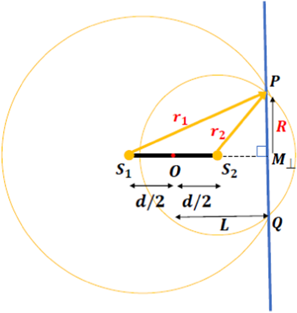
  (see figure 1). The plane of the detection screen is oriented perpendicular to the line joining the two sources. The midpoint
  of the line
  lies at a distance
  from the midpoint
  of the screen. Circular wavefronts of radii
  and
and  that emanate from
  and
and  at different instants of time, expand outwards to meet the screen at P and Q. The interference of these wavefronts result in a pattern of concentric circular bright and dark fringes of radii
  centered about

Figure 1.

 and
and  are the distances of
 and
and  to an arbitrary point
  on the detection screen (blue line), respectively. The midpoint
  of
of  (red dot) lies at distance
  from
from 
Download figure:
Standard image High-resolution image3. Theoretical calculation
Applying Pythagoras' theorem to the two right triangles  and
and 


The magnitude of path difference  is given by,

On algebraic simplification of equation (3), we can obtain the diameter  of a circular fringe that corresponds to a path difference

In order that  the two necessary conditions to be fulfilled are
  and
and  From the geometrical construction shown in figure 1, it is evident that the magnitude of the path difference
  is bounded within the closed interval
 ![$\left[0,d\right].$](https://content.cld.iop.org/journals/2633-1357/2/3/035203/revision2/iopsnac13bbieqn34.gif) Hence, the maximum possible path difference is equal to the inter-source separation, i.e.
Hence, the maximum possible path difference is equal to the inter-source separation, i.e.  Also, since
 ![$\delta \leqslant 2L\,\forall \,{\rm{\delta }}\in \left[0,d\right]\Rightarrow {\delta }_{{\rm{\max }}}\leqslant 2L\Rightarrow d\leqslant 2L.$](https://content.cld.iop.org/journals/2633-1357/2/3/035203/revision2/iopsnac13bbieqn36.gif) Since the screen position
Since the screen position  is physically unfeasible, it follows that the fundamental constraint on the geometry of the arrangement is the strict inequality,

4. Ordering of interference fringes
When the screen is oriented parallel to the line joining  and
and  hyperbolic shaped fringes are formed. If
  be the wavelength of light, then the various (bright) fringe orders
  is given by (see figure 2) [2].

The special brackets  for
for  denotes the floor function. The sign convention used to distinguish the fringes found on the right and left sides of the midline
  has been omitted. When the same screen is oriented perpendicular to the line joining
  and
and  circular shaped fringes are formed (see figure 3). The fringe orders
  in this case, can be inferred from
  after adopting the following definitions,


Figure 2. Hyperbolic shaped interference fringes (yellow dots) are formed on the detection screen (blue line) when it is placed parallel to the line  (black line).
  and
and  are the midpoints of the screen and
  respectively. The distribution of the various (bright) fringe orders
  are depicted for
  (left) and
  (right). Reproduced from [2]. © IOP Publishing Ltd. CC BY 4.0.
Download figure:
Standard image High-resolution image
Figure 3. Circular shaped interference fringes (yellow dots) of radii  centered about
  are formed on the detection screen (blue line) when it is placed perpendicular to the line
  The distribution of the various (bright) fringe orders
  are depicted for
  (left) and
  (right).
Download figure:
Standard image High-resolution imageThe geometrical relationship of the hyperbolic and circular fringe orders can be readily visualized with the help of figures 2 & 3. The numerical relationship of  and
and  is enumerated in table 1. Note that the zeroth order hyperbolic fringe does not correspond to any circular fringe order since the wavefronts from sources
  and
and  in this case, can meet the screen only at infinity. This would require that the circular fringe corresponding to
  be of an infinite diameter. The exclusion of the order
  is thus justified.
Table 1. Hyperbolic-circular fringe order relation: 
Hyperbolic fringe order 
| Circular fringe order 
|
|---|---|

|

|

|

|
| 3 |

|

|

|

|

|

|

|
5. Determination of the diameter of a circular bright fringe
A circular fringe is said to be bright where constructive interference of light from point-sources  and
and  occurs on the orthogonally oriented distant screen. The path difference in this case is a whole number multiple of the wavelength. By writing
  in equation (4), the diameter
  of a circular fringe can be expressed as a function of the hyperbolic fringe order

Alternatively, the diameter can also be expressed as a function of the circular fringe order  by employing the n-m relation (7) in equation (8).
The diameter of the  order circular bright fringe can thus be exactly determined from the experimentally known parameters
5.1. Salient remarks on equation (9)
- (a)The determination of fringe diameter is subject to the constraint

- (b)If the ratio is a natural number, then the zeroth order circular bright fringe lies exactly at the screen center i.e. is occupied by a single bright spot. Formally stated, if then for
- (c)The average fringe density along some radial direction and between the and order circular fringes can be evaluated for a specified interval of fringes as follows,
- (d)The use of the approximation is valid provided that the condition is satisfied. For nearly all practical purposes with light in the visible region, this assumption can be said to hold true.


6. Estimation of the wavelength of light
Equation (4) may be rearranged to form a biquadratic equation in  and then solved algebraically.


This solution satisfies an important feature of the geometrical construction shown in figure 3, namely that  for
for  The wavelength of light
  may be obtained from equation (12) by writing
  and employing the approximation

The estimation of  from the experimentally known parameters
  is subject to three constraints,

7. Estimation of the refractive index of a liquid medium
The passage of light from one optical medium to another is accompanied by a change in its wavelength that is proportionate to the change in its velocity, the frequency remaining unaltered [7]. Let  be the wavelength of monochromatic light in air and
  be its new wavelength upon passing through some liquid medium. The refractive index
  of the latter can be expressed as a ratio of the old to new wavelengths.

Consider an identical arrangement of two point-sources and an orthogonal screen, first immersed in a liquid medium and then in air (see figure 4). From equation (9), it may be inferred that the same  order circular bright fringe (where m > 0) has different diameters, say
  and
and  in the liquid and air, respectively. The refractive index can be calculated based on equations (13) and (15).

The estimation of  from the experimentally known parameters
  is also subject to conditions (14).

Figure 4. Two point-sources  and
and  are suspended inside of a box, aided by a suitable support system (not shown). The walls of the box act as detection screens on which interference fringes can be captured. For the sake of visual clarity, the circular and hyperbolic fringes are depicted only on walls EFGH and BFGC. The diameters of the
  order circular fringe can be readily measured using a well calibrated ruler, when the box is filled with liquid and air.
Download figure:
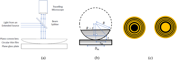
Standard image High-resolution image8. Newton's rings
A circular thin film can be made by placing the convex surface of a plano-convex lens on the top of a plane glass plate, as shown in figure 5. When monochromatic light from an extended source is made to fall on the arrangement at right angles to its surface, a series of concentric alternating bright and dark rings are formed as a consequence of interference of reflected or transmitted light. At the point of contact of the lens with the plate, a central dark spot is seen when viewed in reflected light and a central bright spot is seen when viewed in transmitted light [8]. Historically, these circular fringes were first described by Robert Hooke in his book Micrographia (1664) and then later analyzed by Sir Isaac Newton in his treatise Opticks (1704). Although the original discovery is attributed to Hooke, the rings remain named after Newton [7]. A qualitative and quantitative comparison of Newton's rings and the circular fringes associated with two point-source interference is presented in table 2. Formal details on Newton's rings including its applications viz. the measurement of the wavelength of light and the refractive index of a liquid medium may be found elsewhere [9–12].
Figure 5. (a) Experimental apparatus for the production of Newton's rings, (b) Geometry of the arrangement:  is the radius of curvature of the convex lens,
  is the thickness of the thin (air) film,
  is the radius of the
  order ring and
  is its diameter. Upon applying Pythagoras's theorem for the right triangle shown and using the approximation
  we get
  (c) Newton's rings when seen in reflected light (left) and in transmitted light (right).
Download figure:
Standard image High-resolution image
Table 2. Nature, pattern and production of circular fringes for two point-sources and Newton's rings.
| Characteristic feature | Two point-source rings | Newton's rings |
|---|---|---|
| Source description | Point size | Extended in space |
| Localizability of fringes | These are non-localized fringes that extend throughout the space surrounding the source pair. They are also seen in Young's double slit experiment and special optical arrangements, namely Lloyd's mirror, Fresnel's biprism and Fresnel's mirror. | These are localized fringes visible only at the reflecting/transmitting surface. They are also seen in in wedge shaped thin films (Fizeau fringes) and parallel thin films (Haidinger fringes). |
| Range of fringe orders | There exists a finite order of fringes.
| There exists an infinite order of fringes 
|
| Relationship between fringe diameter and fringe order | The  - - relationship is rather complicated (see equation (9)). relationship is rather complicated (see equation (9)). | The diameter of Newton's (bright) ring is directly proportional to the square root an odd whole number  and the diameter of Newton's (dark) ring is directly proportional to the square root of a whole number and the diameter of Newton's (dark) ring is directly proportional to the square root of a whole number 
|
| Spacing between successive orders of fringes | The quantity  increases with increase of increases with increase of  Thus, the fringes appear more crowded together near the center and spaced apart in the radially outward direction. Thus, the fringes appear more crowded together near the center and spaced apart in the radially outward direction. | The quantity  decreases with increase of decreases with increase of  Thus, the fringes appear more spaced apart near the center and crowded together in the radially outward direction. Thus, the fringes appear more spaced apart near the center and crowded together in the radially outward direction. |
| Average fringe density | Fringe density decreases radially outwards (see equation (10)). | Fringe density increases radially outwards. |
| Central spot | The central spot is bright if  and dark if and dark if  where where 
| The central spot is dark when viewed in reflected light and bright in transmitted light. |
| Geometrical constraint to be satisfied for fringe formation | The orthogonally oriented screen must be placed at a distance greater than half the inter-source separation. That is,  (see equation (5)). (see equation (5)). | The radius of curvature of the convex lens must be much larger than the thickness of the thin film. That is, 
|
9. Summary
In this short paper, the features of concentric circular fringes generated by the interference of light from two coherent point-sources was explored using a hyperbola-based analysis. The geometry of the source-screen arrangement was shown to be suitable for the estimation of the wavelength of light and the refractive index of a liquid medium. The contrasting features of these circular fringes and Newton's rings were qualitatively and quantitatively elucidated.
10. Conclusion
An experiment that is suitably devised towards investigating the proposed theoretical scheme would act as an effective test bed for the hyperbola-based analysis of wave interference. The author therefore, strongly recommends that such a project be taken up by optical researchers.
Acknowledgments
Gloria in excelsis Deo. I wish to thank my parents (Mr. Thomas Varghese and Dr. Annie Susan Thomas), my wife (Dr. Shweta) and my son (Yeshurun) for all their love, encouragement and support.
Data availability statement
All data that support the findings of this study are included within the article (and any supplementary files).