
Abstract
Optimal control problems naturally arise in many scientific applications where one wishes to steer a dynamical system from an initial state x0 to a desired target state  in finite time T. Recent advances in deep learning and neural network–based optimization have contributed to the development of numerical methods that can help solve control problems involving high-dimensional dynamical systems. In particular, the framework of neural ordinary differential equations (neural ODEs) provides an efficient means to iteratively approximate continuous-time control functions associated with analytically intractable and computationally demanding control tasks. Although neural ODE controllers have shown great potential in solving complex control problems, the understanding of the effects of hyperparameters such as network structure and optimizers on learning performance is still very limited. Our work aims at addressing some of these knowledge gaps to conduct efficient hyperparameter optimization. To this end, we first analyze how truncated and non-truncated backpropagation through time affect both runtime performance and the ability of neural networks to learn optimal control functions. Using analytical and numerical methods, we then study the role of parameter initializations, optimizers, and neural-network architecture. Finally, we connect our results to the ability of neural ODE controllers to implicitly regularize control energy.
Export citation and abstract BibTeX RIS

Original content from this work may be used under the terms of the Creative Commons Attribution 4.0 license. Any further distribution of this work must maintain attribution to the author(s) and the title of the work, journal citation and DOI.
1. Introduction
The optimal control (OC) of complex dynamical systems is relevant in many scientific disciplines [1], including biology [2–7], epidemiology [8, 9], quantum engineering [10–12], power systems [13, 14], and supply chains [15].
Mathematically, OC problems can be formulated using variational calculus [16]. The goal is to find a Lebesgue-measurable control signal  (
( ) that steers a dynamical system from its initial state
  to a desired target state
  in finite time T, minimizing the control energy

over the time interval ![$[0,T]$](https://content.cld.iop.org/journals/2632-2153/3/4/045004/revision2/mlstac92c3ieqn6.gif) . Depending on the application, it may be useful to consider additional constraints and integrated cost functionals that are different from equation (1). A corresponding example is provided in appendix
. Depending on the application, it may be useful to consider additional constraints and integrated cost functionals that are different from equation (1). A corresponding example is provided in appendix  are imposed, it has to be chosen from a corresponding set of admissible controls [17].
The outlined OC problem aims at finding

subject to the constraint

where  denotes a vector field that depends on the system state
  , control input
  , and time t. According to Pontryagin's maximum principle (PMP) [18], a necessary condition for OC, the control that satisfies equations (2) and (3) is found by minimizing the corresponding control Hamiltonian

at every time point t. Here,  is a Lagrange multiplier vector whose time-dependent components are called the adjoint (or costate) variables of the system [1, 19]. Linear systems admit a closed-form solution of
  [20]. For general, non-linear dynamical systems, one typically aims at minimizing

where  denotes the distance between the reached state
  and the desired target state
  , e.g. the mean-squared error (MSE)
  . The Lagrange multiplier µ models the impact of control energy on the total loss. Clearly, in the limit
  , we have
  .
.
While PMP provides a necessary condition for OC [18], the Hamilton–Jacobi–Bellman (HJB) equation provides both a necessary and sufficient condition for optimality [21, 22]. To solve non-linear OC problems, one typically resorts to indirect and direct numerical methods. More recently, transformation methods that convert non-linear control problems into linear ones have been proposed [23]. Examples of indirect OC solvers include different kinds of shooting methods [24] that use PMP and a control Hamiltonian to construct a system of equations describing the evolution of state and adjoint variables. In addition to indirect methods, one may also parameterize state and control functions and directly solve the resulting optimization problem. Possible function parameterizations include piecewise constant functions and other suitable basis functions [25]. Over the past two decades, pseudospectral methods have emerged as an effective approach for solving non-linear OC problems [26] with applications in aerospace engineering [27]. However, it has been shown that certain pseudospectral methods are not able to solve standard benchmark control problems [28]. In this work, we represent time-dependent control signals by artificial neural networks (ANNs) [29]. To parameterize and learn control functions, we use neural ordinary differential equations (neural ODEs) [30–34]. A schematic of the application of neural ODE control (NODEC) to a networked dynamical system is shown in figure 1.

Figure 1. Controlling networked dynamical systems with neural ODEs. (a) A neural ODE controller takes the time t as an input variable and produces a control signal  . A networked dynamical system is then controlled by connecting control inputs
  to all or a subset of nodes. Activation functions in the neural ODE controller are denoted by σ. (b), (c) Evolution of x(t), the state of a one-dimensional dynamical system, and of
  , the corresponding control function. Solid grey lines represent x(t) and
  at different training epochs. Solutions after convergence are shown by solid black lines.
Download figure:
Standard image High-resolution imageControl methods that are based on ANNs have been applied to both discrete and continuous-time dynamical systems [35]. To keep calculations associated with gradient updates tractable, applications of ANNs in control have often focused on shallow architectures and linear dynamics. For high-dimensional and non-linear dynamics with intractable gradient updates, 'identifier' ANNs are useful to learn and replace the dynamical system underlying a given control task [35]. Recent advances in neural ODEs [31] and automatic differentiation [36] allow for the direct application of deep neural network architectures to high-dimensional non-linear models [33], thereby avoiding identifier networks [35] and limitations associated with shallow ANN structures. Other popular uses of ANNs for control are found in the fields of deep reinforcement learning [37] and neural HJB methods [38]. Deep reinforcement learning is often applied to model-free control tasks where the model dynamics are unknown or non-differentiable [39]. Neural HJB methods have been applied to state-feedback control and rely on the existence of smooth value functions [38]. Instead of explicitly minimizing control energy or other loss functionals, neural ODE controllers have been shown to exhibit implicitly regularization properties [33, 34]. In this work, we study the effect of learning protocols and hyperparameters such as network structure and optimizers on the ability of NODEC to implicitly learn near-optimal control solutions by minimizing the distance between reached and target state.
The remainder of this paper is organized as follows. Section 2 summarizes the basic concepts associated with NODEC and discusses two different backpropagation protocols for learning control functions: (i) truncated backpropagation through time (TBPTT) and (ii) backpropagation through time (BPTT) [40–42]. In section 3, we discuss how parameter initialization and activation functions affect NODEC's ability to implicitly learn OC solutions. Invoking tools from dynamical systems theory, we discuss how different neural network structures affect the learnability of a constant control solution. We will show that single neurons are able to learn OC solutions only for certain initial weights and biases. Numerical results presented in section 4 indicate that as the depth of the employed neural network increases, initial conditions have a smaller impact on the ability of NODEC to learn a near-OC solution. In section 5, we analyze how gradients in the neural network parameters induce gradient updates in both the control function and control energy. By applying NODEC to a control problem with a time-dependent OC solution, we find that adaptive gradient methods such as Adam [43] are able to approximate OC well while steepest descent (SD) fails to do so. We complement this part of our analysis with one and two-dimensional loss projections [44–49] that are useful to geometrically interpret the tradeoff between (i) a small distance between reached and target state and (ii) a small control energy. Section 6 concludes our paper.
Our source codes are publicly available at [50].
2. Backpropagation protocols
The basic steps underlying NODEC solutions of OC problems (3) are summarized below [34].
- (a)Parameterize the control input
 using a neural network such that equation (3) becomes The vector denotes the neural-network parameters.
 - (b)Solve the dynamical system (6) numerically for a given initial condition.
- (c)Calculate the MSE between reached state and target state and backpropagate gradients to update neural-network weights.
- (d)Iterate steps (a)–(c) until convergence is reached (i.e. until is smaller than a certain threshold).


Instead of learning the vector field f as in related applications of neural ODEs [30, 31], we use ANNs to represent time-dependent control functions  (see figure 1(a)).
We will discuss in the following sections that control solutions with a small control energy ![$E_T[\mathbf{u}]$](https://content.cld.iop.org/journals/2632-2153/3/4/045004/revision2/mlstac92c3ieqn31.gif) can be obtained without explicitly including
can be obtained without explicitly including ![$E_T[\mathbf{u}]$](https://content.cld.iop.org/journals/2632-2153/3/4/045004/revision2/mlstac92c3ieqn32.gif) in the loss function. Even if the control energy is included directly in the loss function, one may still have to search for a Lagrange multiplier µ (see equation (5)) that is associated with a desired tradeoff between control energy and distance from the target state. We provide a corresponding example in appendix
in the loss function. Even if the control energy is included directly in the loss function, one may still have to search for a Lagrange multiplier µ (see equation (5)) that is associated with a desired tradeoff between control energy and distance from the target state. We provide a corresponding example in appendix
To learn control functions that are suitable to solve a certain control problem minimizing the MSE between reached and target state, there exist two main classes of backpropagation protocols: (i) truncating backpropagation and approximating a desired control function within a certain subinterval of ![$[0,T]$](https://content.cld.iop.org/journals/2632-2153/3/4/045004/revision2/mlstac92c3ieqn33.gif) , and (ii) learning the control input over the whole interval
, and (ii) learning the control input over the whole interval ![$[0,T]$](https://content.cld.iop.org/journals/2632-2153/3/4/045004/revision2/mlstac92c3ieqn34.gif) using BPTT. The first option is also referred to as TBPTT.
using BPTT. The first option is also referred to as TBPTT.
In the following two subsections, we will discuss the differences between BPTT and TBPTT with respect to (w.r.t.) learning control functions. We will also provide an example to compare the performance of BPTT and TBPTT.
2.1. Truncated backpropagation through time
For notational brevity, we will consider a TBPTT protocol for a one-dimensional flow  where neural-network parameters
θ
are being updated for a time tʹ in the loss function
where neural-network parameters
θ
are being updated for a time tʹ in the loss function  . Gradients are calculated through the loss function if the underlying dynamical system time t is equal to tʹ. Generalizations for multiple evaluation times and higher-dimensional flows follow directly from the equations below. The TBPTT gradient of L w.r.t.
θ
is
. Gradients are calculated through the loss function if the underlying dynamical system time t is equal to tʹ. Generalizations for multiple evaluation times and higher-dimensional flows follow directly from the equations below. The TBPTT gradient of L w.r.t.
θ
is

where  is a small positive number that determines the width of the TBPTT interval. Note that
  can be absorbed in the learning rate associated with gradient-descent updates of
θ
. The Jacobian of
can be absorbed in the learning rate associated with gradient-descent updates of
θ
. The Jacobian of  w.r.t.
θ
is
w.r.t.
θ
is

In the described TBPTT protocol, we used that

2.2. Backpropagation through time
Without truncating the BPTT protocol, the gradient of L w.r.t. θ is

where the notation ![$I\left[D_{\hat{u}}x(T), \mathcal{J}_{\hat{u}}^\top\right]$](https://content.cld.iop.org/journals/2632-2153/3/4/045004/revision2/mlstac92c3ieqn40.gif) is used to indicate that the integration associated with the derivative
is used to indicate that the integration associated with the derivative  has to be applied to
  . Note that
  is not time-dependent, while the derivative of the loss function L w.r.t.
  is an operator that acts on the time-dependent quantity
  .
.
We will now compare BPTT and TBPTT protocols for controlling the two-dimensional linear flow

with

The OC  associated with solving equation (11) and minimizing
 ![$E_T[\mathbf{u}]$](https://content.cld.iop.org/journals/2632-2153/3/4/045004/revision2/mlstac92c3ieqn52.gif) (see equation (1)) has been derived in [20]. We compare the optimal solution with the solutions obtained using (T)BPTT and the MSE loss
(see equation (1)) has been derived in [20]. We compare the optimal solution with the solutions obtained using (T)BPTT and the MSE loss

Figure 2(a) shows the evolution of  in the
  plane. Both backpropagation protocols, BPTT and TBPTT, produce solutions after 1000 epochs of training that are similar to the OC solution. This similarity is also reflected in the evolution of the control signal and control energy (see figures 2(b) and (c)). To solve equation (11) numerically, we use a forward Euler method with step size 0.01. In the TBTT protocol, we use a different gradient evaluation time tʹ in each backpropagation step. While carrying out our numerical experiments, we observe that convergence of both methods is sensitive to choice of learning rate and optimizer. Figure 2(d) shows that BPTT converges faster with a smaller learning rate, but at later stages in training it becomes less stable. On the contrary, TBPTT, converges slower with a higher learning rate, but it is more stable after convergence. Under the employed parametrization, both methods are capable to converge fast to low error values. In terms of computation time, on the same hardware and according to tqdm library measurements, BPTT performs around 65 training epochs per second, whereas TBPTT achieves approximately 125 epochs per second. The difference in total computation time may be attributed to the fewer gradient evaluations required by TBPTT.

Figure 2. Learning control functions with different backpropagation protocols. (a) The evolution of  of the solution of equation (11) in the
  plane. (b), (c) The evolution of the corresponding control function and control energy. The OC solution is indicated by a dashed grey line. Dashed blue lines and dotted red lines show the solutions associated with BPTT and TBPTT protocols, respectively. The underlying neural network has 2 hidden exponential linear unit (ELU) layers and 14 neurons per hidden layer. We trained the neural network for 1000 epochs using Adam. The learning rates are
  (BPTT) and
  (TBPTT). (d) The loss
  as a function of training epochs n. Both backpropagation protocols can achieve low loss values after a few hundred epochs of training.
Download figure:
Standard image High-resolution image3. Parameter initialization and activation functions
As shown in section 2 and in previous work [33, 34], NODEC is able to learn near-OC solutions without explicitly minimizing ![$E_T[\mathbf{u}]$](https://content.cld.iop.org/journals/2632-2153/3/4/045004/revision2/mlstac92c3ieqn55.gif) . To provide insights into the learning dynamics underlying NODEC, we study two control problems associated with a one-dimensional linear flow. The first dynamical system has a constant OC solution while that of the second dynamical system is time-dependent. In this section, we will show that shallow architectures require one to tune initial weights and biases to learn OC solutions without accounting for a control energy term in the loss function. The next section then provides numerical evidence that deeper architectures are less prone to such weight and bias initialization effects.
. To provide insights into the learning dynamics underlying NODEC, we study two control problems associated with a one-dimensional linear flow. The first dynamical system has a constant OC solution while that of the second dynamical system is time-dependent. In this section, we will show that shallow architectures require one to tune initial weights and biases to learn OC solutions without accounting for a control energy term in the loss function. The next section then provides numerical evidence that deeper architectures are less prone to such weight and bias initialization effects.
3.1. Constant control
We first consider the OC problem associated with the scalar control function

subject to a constraint that is given by the state-independent, one-dimensional flow

The corresponding control Hamiltonian (see equation (4)) is

We use PMP to derive  , which we will assume to be the OC associated with equations (14) and (15). We obtain


Integrating equation (15) with  yields

where we used that the reached state x(T) is equal to the target state  . The OC is
  .
.
A simple neural network that consists of a single rectified linear unit (ReLU) and uses the time t as an input is, in principle, able to represent the constant OC  . For a neural network–generated control signal
  , where
  , we have
  if
if  and
and  .
.
Near-optimal control solutions have been obtained representing control functions by neural ODEs and optimizing

without explicitly accounting for the integrated cost or control energy (1) [34]. Under what conditions (e.g. initial weights and biases, optimization algorithm, and neural-network structure) can a neural network learn a control function  that is close to
  by optimizing equation (20)? As a starting point for addressing this question, we will focus on analytically tractable learning algorithms and neural network structures. In the following sections, we will then use these gained insights to draw conclusions for control problems that involve higher-dimensional neural network structures and generalized optimization algorithms.
3.1.1. Single-neuron structure with linear activation
In the following example, we use simple neural network that consists of a linear activation and a weight and bias parameter (see figure 3(a)). The corresponding loss function is

Using steepest-descent learning and BPTT, weights and biases are iteratively updated according to

where  and
and  denote initial weight and bias, respectively. The quantity η denotes the learning rate. Using the loss function (21), the gradients in equation (22) are

The fixed points  associated with equation (23) satisfy


Figure 3. Examples of single-neuron structures. (a) The input is the time t and the output is  . (b) The input is the time t and the output is
  .
.
Download figure:
Standard image High-resolution imageFor T = 1,  , and
, and  , the fixed points are given by
  . Recall that, in this example, the weight and bias of OC are
  and
and  . This fixed point can only be reached for specific initializations as shown in figures 4(a) and (b). Other fixed points are associated with certain tradeoffs between small control energies

and small losses  (see figures 4(c) and (d)).

Figure 4. Approximating constant control with a linear activation function. (a) The mean squared error (MSE) associated with the deviation of the learned weight and bias,  , from the OC weight and bias,
  , for different initial weights
  and biases
  . The solid white line indicates the location of initial weights and biases for which gradient-descent learning converges to OC. (b) Solid red lines and filled red squares indicate learning trajectories and learned parameters
  , respectively. The solid black line represents fixed points of steepest-descent learning [i.e.
  as defined in equation (24)]. The fixed point
  corresponding to the OC solution is marked by a black circle. (c) The control energy
 ![$E_T[u]$](https://content.cld.iop.org/journals/2632-2153/3/4/045004/revision2/mlstac92c3ieqn80.gif) (see equation (1)) as a function of learned neural-network weights
(see equation (1)) as a function of learned neural-network weights  . Energies associated with Adam-based simulation results and steepest-descent fixed points are indicated by filled red squares and a solid black line, respectively. The dashed grey line marks the energy associated with OC. (d) Control energy as a function of the loss function (21). In all simulations, we set T = 1,
  , and
, and  . We trained the controller with Adam using a learning rate η = 0.1 for 100 epochs.
Download figure:
Standard image High-resolution image3.1.2. Single-neuron structure with ReLU activation
We now use a slightly different neural-network structure that consists of a single ReLU (see figure 3(b)). The loss function in this example is

If the weights are larger than or equal to 0, the steepest-descent equations are equivalent to equation (23). Otherwise, we have

If  for some n, the fixed point of the gradient descent (27) is equivalent to the OC
  . Figures 5(a) and (b) shows that the optimal-control domain of equation (26) is substantially larger than that resulting from a gradient descent in equation (21). The control energy approaches that of OC for
  , while larger values of
  are associated with larger control energies (see figure 5(c)). As in the previous example, one can observe that tradeoffs between small control energies and small losses are possible (see figure 5(d)).

Figure 5. Approximating constant control with a ReLU activation function. (a) The mean squared error (MSE) associated with the deviation of the learned weight and bias,  , from the OC weight and bias,
  , for different initial weights
  and biases
  . The deep purple region indicates initial weights and biases for which the neural network learns OC. In the yellow region, OC cannot be learned. (b) Solid red lines and filled red squares indicate learning trajectories and learned parameters
  , respectively. The solid black line represents the attractor of steepest-descent learning [i.e.
  if
if  and
and  if
if  ]. The attractor
  corresponds to OC. (c) The control energy
 ![$E_T[u]$](https://content.cld.iop.org/journals/2632-2153/3/4/045004/revision2/mlstac92c3ieqn100.gif) (see equation (1)) as a function of learned neural-network weights
(see equation (1)) as a function of learned neural-network weights  . Energies associated with Adam-based simulation results and steepest-descent fixed points are indicated by filled red squares and the solid black line, respectively. The dashed grey line marks the energy associated with OC. (d) Control energy as a function of the loss function (21). In all simulations, we set T = 1,
  , and
, and  . We trained the controller with Adam using a learning rate η = 0.1 for 100 epochs.
Download figure:
Standard image High-resolution imageEquation (27) also shows that the OC solution associated with equation (15) is a global attractor if one would just learn a bias term, reflecting the fact that the OC is given by a constant.
3.2. Time-dependent control
To study the ability of NODEC to learn time-dependent control functions, we consider the OC problem

subject to

A practical application of this OC problem is temperature control in a room [53]. The corresponding OC signal is

Note that for a > 0 the magnitude of  decays exponentially because larger values of t are associated with larger state values of the uncontrolled dynamics
  . The opposite holds for a < 0. The evolution of the system state x(t) under the influence of
  is
is

and the control energy associated with the OC signal (30) is

As in the prior examples, we use NODEC to learn  by minimizing the MSE loss (20). We set
  and
and  , such that
  ,
,  , and
, and ![$E_T[u^*] = 1/(e^2-1)\approx 0.157$](https://content.cld.iop.org/journals/2632-2153/3/4/045004/revision2/mlstac92c3ieqn118.gif) . To capture the time-dependence of the control input, we use a neural network with two hidden layers and six exponential linear units (ELUs) per hidden layer. Numerical experiments with smaller architectures showed that the exponential decay of the OC solution could not be captured well. The number of timesteps in our simulations is 100. If bias and weight values are initialized to 1, NODEC is able to steer the dynamical system toward the desired target state (see figure 6(a)). For a learning rate of about 0.12, we observe that NODEC approximates the OC solution by a constant control with a similar control energy (see figures 6(b) and (c)). The relative difference between the two control energies is about 3.5%. Using smaller initial weights and biases can help NODEC approximate the OC solution even more closely (see figures 6(d)–(f)). We find a minimum relative control energy difference of less than 0.2%. Earlier work [34] also suggested that small initial weights and biases can be helpful for learning OC solutions without explicitly regularizing control energy.
. To capture the time-dependence of the control input, we use a neural network with two hidden layers and six exponential linear units (ELUs) per hidden layer. Numerical experiments with smaller architectures showed that the exponential decay of the OC solution could not be captured well. The number of timesteps in our simulations is 100. If bias and weight values are initialized to 1, NODEC is able to steer the dynamical system toward the desired target state (see figure 6(a)). For a learning rate of about 0.12, we observe that NODEC approximates the OC solution by a constant control with a similar control energy (see figures 6(b) and (c)). The relative difference between the two control energies is about 3.5%. Using smaller initial weights and biases can help NODEC approximate the OC solution even more closely (see figures 6(d)–(f)). We find a minimum relative control energy difference of less than 0.2%. Earlier work [34] also suggested that small initial weights and biases can be helpful for learning OC solutions without explicitly regularizing control energy.

Figure 6. Approximating time-dependent control. We use NODEC to control equation (29) for  and
and  . The neural network that we use in this example consists of 2 hidden layers with 6 ELU neurons each. (a)–(c) Initial weights and biases are set to 1. (d)–(f) Initial weights and biases are set to 0.1. Different solid red lines are associated with different learning rates. Solid black lines indicate OC solutions (30)–(32). We trained NODEC for 1000 epochs using Adam.
Download figure:
Standard image High-resolution image4. Neural network depth and width
After having discussed the effect of parameter initialization on the ability of NODEC to implicitly learn OC solutions, we will now study how different numbers of layers and neurons per layer can help improve learning performance in the context of the examples from section 3.
4.1. Constant control
We first focus on the ability of deeper ANN architectures to implicitly learn a constant control function for the example that we discussed in section 3.1. The OC signal is  , and we use an ANN with hyperbolic tangent activations, between one to nine layers, and up to 1100 neurons. Weights and biases are initially distributed according to
  , where k denotes the number of input features of a certain layer. Figure 7(a) shows that an increase in the number of layers is associated with a decrease in control energy toward the optimal value of 0.5. Even if the number of layers increases, loss values are still small and almost unaffected by the change of the ANN architecture (see figure 7(b)). Increasing the number of layers also helps in learning constant controls, as the temporal mean
  is close to the optimal constant control value for most simulated scenarios with many layers (see figure 7(c)) while the corresponding variance
  gets closer to 0 (see figure 7(d)). To summarize, we observe that adding layers is more beneficial than adding more neurons in order to approximate a constant OC function.

Figure 7. Effect of variations in number of layers and neurons per layer on the ability of NODEC to learn a constant control signal. The underlying architectures use hyperbolic tangent activations in all hidden layers. Bias terms are not included. Each ANN is trained for 100 epochs using Adam and a learning rate  . We set the number of neurons per layer to be the greatest integer less than or equal to the maximum number of neurons (vertical axes) divided by the number of layers (horizontal axes). The optimal constant control is −1 and the OC energy is
  . Heatmaps show the (a) control energy
 ![$E_T[\hat{u}]$](https://content.cld.iop.org/journals/2632-2153/3/4/045004/revision2/mlstac92c3ieqn121.gif) , (b) loss
, (b) loss  , (c) mean control signal over time
  , and (d) control signal variance over time,
  .
.
Download figure:
Standard image High-resolution image4.2. Time-dependent control
For learning the time-dependent control signal that we studied in section 3.2, we use an ANN with ELU activations, between one to nine layers, and up to 90 neurons. Weights and biases are initially distributed according to  , where k denotes the number of input features of a certain layer. Figure 8(a) shows that smaller control energies can be achieved on average as the number of layers increases. For one or eight layers and 30 neurons in total, we observe that the ANN controller is able to implicitly learn a solution with a small loss and a control energy that is close to that of the optimal solution. However, the loss may increase with the number of layers (see figure 8(b)). Increasing the number of layers while keeping a relatively small number of neurons per layer seems to affect convergence as most ANNs seem to converge to a non-optimal constant control—the corresponding variances in figure 8(d) are close to 0 (darker color). We show in section 5.3 that the constant OC approximation of equation (30) has a control energy of about 0.169 (see figure 8). In this example, we find that implicit regularization of control energy can be achieved by selecting appropriate hyperparameters (e.g. one or eight layers and 30 neurons in total).

Figure 8. Effect of variations in number of layers and neurons per layer on the ability of NODEC to learn the time-dependent control signal (30) for  and
and  . The underlying architectures use bias terms and ELU activations in all hidden layers. Each ANN is trained for 500 epochs using Adam and a learning rate
  . We set the number of neurons per layer to be the greatest integer less than or equal to the maximum number of neurons (vertical axes) divided by the number of layers (horizontal axes). The OC energy is approximately 0.157. Heatmaps show the (a) control energy
 ![$E_T[\hat{u}]$](https://content.cld.iop.org/journals/2632-2153/3/4/045004/revision2/mlstac92c3ieqn132.gif) , (b) loss
, (b) loss  , (c) mean control signal over time
  , and (d) control signal variance over time,
  .
.
Download figure:
Standard image High-resolution imageIn appendix
5. Implicit energy regularization
For sufficiently small changes in the neural-network parameters  (i.e. a sufficiently small learning rate η), a steepest-descent update in
  changes a control input according to

where  . The gradient
  can be evaluated with BPTT and TBPTT protocols (see equations (7) and (10)). We will now study the evolution of control inputs under neural-network parameter updates.
5.1. Induced gradient update
For the linear one-dimensional flow (29), we have

and

Using the BPTT notation introduced in section 2, we obtain


Invoking equation (33), the induced gradient update in  is
is

Based on equation (38), we define the weighted total change in  for the linear dynamics (29) as

where  can be directly evaluated with standard backpropagation methods, thus avoiding the evaluation of the Jacobian elements
  in equation (33).
Figure 9 shows a comparison of learned control signals  for the linear dynamics (29) with
  and
and  . The neural network that we use in this example consists of 2 hidden layers with 6 ELU neurons each. Weights and biases are initialized to values of 0.1. SD fails to approximate the OC signal (see figure 9(a)), whereas Adam is able to approach the OC function (see figure 9(b)). We again emphasize that the learning loss is proportional to the squared difference between reached state and target state
  (see equation (21)). Learning the OC solution is not a direct learning target. Still, in the discussed example, learning OC is possible with the Adam optimizer. As described by equations (33)–(38), a gradient descent in
  may induce a gradient update in
  . Because the Jacobian
  is usually not straightforward to evaluate, we use
  to study if the linearization of
  in
in  is justified. Figure 9(c) shows that
  (red squares) is well-described by
  (solid red line). The evolution of
  under Adam (solid blue line) undergoes oscillations.

Figure 9. Learning control signals with SD and Adam. We use NODEC to control equation (29) for  and
and  . (a), (b) Learned and OC signals are indicated by solid red and black lines, respectively ((a) SD; (b) Adam). Different solid red lines correspond to control functions
  learned after different numbers of epochs n. The learning rate was set to η = 0.15. The neural network that we use in this example consists of 2 hidden layers with 6 ELU neurons each. Initial weights and biases are set to 0.1. Solid black lines indicate the OC signal (30). (c) The weighted total change
  (see equation (39)) as a function of epochs n. Red squares (SD) and the blue solid line (Adam) are based on directly evaluating
  . The solid red line is based on evaluating the right-hand side of equation (39) using neural-network parameter changes
  associated with SD.
Download figure:
Standard image High-resolution image5.2. Control energy regularization
The induced gradient update in the control input  and the evolution of the control energy
 ![$E_T[\hat{\mathbf{u}}]$](https://content.cld.iop.org/journals/2632-2153/3/4/045004/revision2/mlstac92c3ieqn159.gif) during training are connected via
during training are connected via


Using the identity ![$\nabla_{\boldsymbol{\theta}^{(n)}} E_T[\hat{\mathbf{u}}^{(n)}] = \int_0^T\mathcal{J}_{\hat{\mathbf{u}}^{(n)}}^\top \hat{\mathbf{u}}(t;\boldsymbol{\theta}^{(n)})\,\mathrm{d}t$](https://content.cld.iop.org/journals/2632-2153/3/4/045004/revision2/mlstac92c3ieqn160.gif) , we obtain
, we obtain

Equation (42) shows that, up to terms of order  , a gradient-descent update in
  is associated with a control energy update that is equal to
 ![$(\nabla_{\boldsymbol{\theta}^{(n)}} E_T[\hat{\mathbf{u}}^{(n)}])^\top$](https://content.cld.iop.org/journals/2632-2153/3/4/045004/revision2/mlstac92c3ieqn163.gif) multiplied by
multiplied by  . Let ω denote the angle between
 ![$\nabla_{\boldsymbol{\theta}^{(n)}} E_T[\hat{\mathbf{u}}^{(n)}]$](https://content.cld.iop.org/journals/2632-2153/3/4/045004/revision2/mlstac92c3ieqn165.gif) and
and  . If
. If  (i.e.
(i.e.  ), a gradient update in
  is associated with a decrease in control energy. The control energy increases for
  (i.e.
(i.e.  ) and it stays constant for
  (i.e.
(i.e.  ).
).
Table 1 provides an overview of the gradient updates associated with the neural-network parameters  , control function
  , and control energy
 ![$E_T[\hat{\mathbf{u}}^{(n)}]$](https://content.cld.iop.org/journals/2632-2153/3/4/045004/revision2/mlstac92c3ieqn202.gif) .
.
Table 1. Overview of gradient updates of neural-network parameters, control function, and control energy.
| Neural-network parameters |

|
| Control function |

|
| Control energy |
![$E_T[\hat{\mathbf{u}}^{(n+1)}] = E_T[\hat{\mathbf{u}}^{(n)}]-\eta(\nabla_{\boldsymbol{\theta}^{(n)}} E_T[\hat{\mathbf{u}}^{(n)}])^\top\nabla_{\boldsymbol{\theta}^{(n)}}L$](https://content.cld.iop.org/journals/2632-2153/3/4/045004/revision2/mlstac92c3ieqn182.gif)
|
Using random projections of the loss function L [45] can help provide geometric intuition for the interplay between explicit minimization of L and implicit regularization of the control energy ![$E_T[\hat{\mathbf{u}}]$](https://content.cld.iop.org/journals/2632-2153/3/4/045004/revision2/mlstac92c3ieqn203.gif) . To obtain two and three-dimensional projections of the 51-dimensional parameter space of the employed neural networks, we set the neural-network parameters
. To obtain two and three-dimensional projections of the 51-dimensional parameter space of the employed neural networks, we set the neural-network parameters  around a local optimum
  . Here,
  denote scaling parameters and
  are random Gaussian vectors.
For an Adam-based optimization of the OC problem (29), figure 10 shows two and three-dimensional random projections of  ,
, ![$E_T[\hat{u}]$](https://content.cld.iop.org/journals/2632-2153/3/4/045004/revision2/mlstac92c3ieqn209.gif) , and
, and

quantifying the deviation of  from the optimum
  . Here, M is the number of timesteps and
  . In the random projection shown in figure 10, we observe that Adam produces a local optimum that is associated with a small loss,
  , and control energy. In comparison with the results obtained with SD (see figure 11), we observe that Adam produces sharper local optima. The loss projection that we show in figure 11 also suggests that SD produces two 'valleys' of local optima separated by a plateau. Escaping from a local optimum located in one valley to another optimum in the second valley may be challenging as even larger learning rates may not be able to overcome the plateau. Additional loss projections for neural networks with fewer parameters are provided in appendix

Figure 10. Loss landscapes for training with Adam. Around a local optimum  obtained after 1000 training epochs, we set the neural-network parameters
  , where
  . (a), (d) The loss
  (see equation (20)) for
 ![$\alpha\in [-0.4,0.4]$](https://content.cld.iop.org/journals/2632-2153/3/4/045004/revision2/mlstac92c3ieqn187.gif) , β = 0 (a) and
, β = 0 (a) and ![$\alpha,\beta\in[-0.4,0.4]$](https://content.cld.iop.org/journals/2632-2153/3/4/045004/revision2/mlstac92c3ieqn188.gif) (b). (b), (e) The MSE associated with the difference between
(b). (b), (e) The MSE associated with the difference between  and
and  ,
,  (see equation (43)), as a function of
 ![$\alpha\in [-0.4,0.4]$](https://content.cld.iop.org/journals/2632-2153/3/4/045004/revision2/mlstac92c3ieqn192.gif) (b) and
(b) and ![$\alpha,\beta\in[-0.4,0.4]$](https://content.cld.iop.org/journals/2632-2153/3/4/045004/revision2/mlstac92c3ieqn193.gif) (e). (c), (f) The control energy
(e). (c), (f) The control energy ![$E_T[\hat{u}]$](https://content.cld.iop.org/journals/2632-2153/3/4/045004/revision2/mlstac92c3ieqn194.gif) (see equation (1)) as a function of
(see equation (1)) as a function of ![$\alpha\in [-0.4,0.4]$](https://content.cld.iop.org/journals/2632-2153/3/4/045004/revision2/mlstac92c3ieqn195.gif) (c) and
(c) and ![$\alpha,\beta\in[-0.4,0.4]$](https://content.cld.iop.org/journals/2632-2153/3/4/045004/revision2/mlstac92c3ieqn196.gif) (f). The OC energy,
(f). The OC energy,  , is indicated by a dashed black line in panel (c). The neural network that we use in this example consists of 2 hidden layers with 6 ELU neurons each. Parameters of the underlying dynamical system (29) are set to
  and
and  . We used Adam to train the neural network and set the learning rate to η = 0.15. Initial weights and biases were set to 0.1.
Download figure:
Standard image High-resolution image
Figure 11. Loss landscapes for training with SD. Around a local optimum  obtained after 1000 training epochs, we set the neural-network parameters
  , where
  . (a), (d) The loss
  (see equation (20)) as a function of
 ![$\alpha\in [-0.4,0.4]$](https://content.cld.iop.org/journals/2632-2153/3/4/045004/revision2/mlstac92c3ieqn218.gif) , β = 0 (a) and
, β = 0 (a) and ![$\alpha,\beta\in[-0.4,0.4]$](https://content.cld.iop.org/journals/2632-2153/3/4/045004/revision2/mlstac92c3ieqn219.gif) (b). (b), (e) The MSE associated with the difference between
(b). (b), (e) The MSE associated with the difference between  and
and  ,
,  (see equation (43)), as a function of
 ![$\alpha\in [-0.4,0.4]$](https://content.cld.iop.org/journals/2632-2153/3/4/045004/revision2/mlstac92c3ieqn223.gif) (b) and
(b) and ![$\alpha,\beta\in[-0.4,0.4]$](https://content.cld.iop.org/journals/2632-2153/3/4/045004/revision2/mlstac92c3ieqn224.gif) (e). (c), (f) The control energy
(e). (c), (f) The control energy ![$E_T[\hat{u}]$](https://content.cld.iop.org/journals/2632-2153/3/4/045004/revision2/mlstac92c3ieqn225.gif) (see equation (1)) as a function of
(see equation (1)) as a function of ![$\alpha\in [-0.4,0.4]$](https://content.cld.iop.org/journals/2632-2153/3/4/045004/revision2/mlstac92c3ieqn226.gif) (c) and
(c) and ![$\alpha,\beta\in[-0.4,0.4]$](https://content.cld.iop.org/journals/2632-2153/3/4/045004/revision2/mlstac92c3ieqn227.gif) (f). The OC energy,
(f). The OC energy,  , is indicated by a dashed black line in panel (c). The neural network that we use in this example consists of 2 hidden layers with 6 ELU neurons each. Parameters of the underlying dynamical system (29) are set to
  and
and  . We used SD to train the neural network and set the learning rate to η = 0.15. Initial weights and biases were set to 0.1.
Download figure:
Standard image High-resolution image5.3. Constant OC approximation
In situations where the OC function is expected to only vary modestly in time, or when no good guess of the OC solution is available, one may use a constant control approximation as a baseline. For such a baseline, the underlying neural network consists of a bias term (i.e.  ) and equation (33) becomes

where  . For linear dynamics (29) with
  and
and  , the loss function (35) becomes

In the limit  , the control function approaches
  and in each gradient-descent step, the control energy changes according to


Figure 12 shows the evolution of  ,
, ![$E_T[\hat{u}^{(n)}]$](https://content.cld.iop.org/journals/2632-2153/3/4/045004/revision2/mlstac92c3ieqn245.gif) , and
, and  . Solid red and blue lines represent solutions that were obtained with SD and Adam, respectively. Dashed black lines in figures 12(a) and (b) indicate the OC solutions. The convergence behavior of Adam is non-monotonic. Between 60 and 70 training epochs, Adam achieves control energy values smaller than
 ![$E_T[\hat{u}^{(\infty)}] = 1/2(e-1)^{-2}$](https://content.cld.iop.org/journals/2632-2153/3/4/045004/revision2/mlstac92c3ieqn247.gif) , owing to an increase in the loss
, owing to an increase in the loss  . The ratio between
 ![$E_T[\hat{u}^{(\infty)}] = 1/2(e-1)^{-2}$](https://content.cld.iop.org/journals/2632-2153/3/4/045004/revision2/mlstac92c3ieqn249.gif) and the OC energy is 1.08, indicating that the constant control approximation achieves a control energy that is close to that of the corresponding OC solution.
and the OC energy is 1.08, indicating that the constant control approximation achieves a control energy that is close to that of the corresponding OC solution.

Figure 12. Approximating OC by a constant. (a) The constant control input  as a function of the number of training epochs n. The dashed black line indicates the optimum
  . (b) The control energy
 ![$E_T[\hat{u}^{(n)}]$](https://content.cld.iop.org/journals/2632-2153/3/4/045004/revision2/mlstac92c3ieqn239.gif) as a function of n. In the limit
as a function of n. In the limit  , the control energy approaches
  (dashed black line). (c) The MSE loss
  as a function of n. Solid red and blue lines represent SD and Adam solutions, respectively. We set the learning rate to
  .
.
Download figure:
Standard image High-resolution imageThe constant control baseline that we derived in this section also appears to be close to possible local optima that are learned by NODEC. For example, for certain learning rates and initial values of neural-network parameters, Adam approaches solutions that are similar to the constant baseline (see figures 6(b) and (e)). We also observe a similar behavior for steepest-descent learning (see figure 9(a)). One of the loss projections in appendix
6. Discussion
Optimal control problems arise in various applications and often admit analytical solutions only under special assumptions (e.g. for linear systems [20]). For non-linear control problems, different direct and indirect numerical methods have been developed to approximate OC solutions. The loss function underlying OC problems consists of a final cost (e.g. difference between reached and target state) and an integrated cost (e.g. control energy). To achieve a certain tradeoff between these two cost contributions, one has to find suitable Lagrange multipliers (see equation (5)), which might prove challenging in practice. Neural ODE controllers provide an alternative to standard direct and indirect OC solvers in that they are able to implicitly learn near-optimal control functions [33, 34] if the underlying hyperparameters are chosen appropriately. The problem of optimizing Lagrange multipliers in OC loss functionals can be recast into a hyperparameter optimization problem, with the goal being that the basin of attraction of the desired OC solution in the underlying loss landscape is sufficiently large.
To study the ability of neural ODE controllers to perform implicit control energy regularization, we have analyzed the influence of backpropagation protocols, parameter initialization, optimizers, and activation functions on the learned control solutions. Using analytical and numerical arguments, we were able to identify different features that can help NODEC designers to efficiently perform hyperparameter optimization and learn near-optimal control solutions.
First, TBPTT has been shown to be computationally more efficient in terms of iterations per unit time than its untruncated counterpart. Although TBPTT protocols only provide an approximation of the actual gradient update, our results suggest that they can achieve loss values and control solutions that are similar to those obtained with untruncated gradient updates. Future work may evaluate the computational advantages of TBPTT over BPTT in larger-scale problems.
Second, a useful starting point for certain control problems may be a constant controller that can be represented by a bias term. Constant OC approximations appeared as local optima in deeper architectures that we used in our numerical experiments. For high-dimensional control tasks studied in earlier work [34], NODEC has also learned a constant OC approximation that provided better performance than solutions found by an adjoint-gradient method (i.e. an indirect OC solver). Increasing the width and depth of the underlying ANN can substantially improve the performance of NODEC in implicitly learning near-optimal control solutions as shown in section 4. Between four to six hidden fully-connected layers and about five to ten neurons per hidden layer have shown good performance in different control tasks. In accordance with earlier numerical work [34], our results also highlight the importance of appropriate initialization protocols. Large weight and bias values may often be associated with loss values that are far away from the basin of attraction of a near-OC solution. In this context it may be worthwhile to study combinations of neural-network parameter initialization protocols and momentum schedulers [54].
Third, adapative gradient methods like Adam have been shown to be able to learn near-OC functions in problems where SD fails to do so. These results therefore contribute to the discussion of the advantages of adaptive optimizers over standard gradient descent techniques [55–57]. Two and three dimensional loss projections provide insights into hyperparameter-dependent geometric features of the loss and control energy landscapes and may reveal the existence of better nearby local optima.
There are different possibilities for future work. Studying the ability of neural ODE controllers to implicitly learn control functions for loss functionals different from equation (5) can help provide insights into the properties of generalized implicit regularization approaches. It would also be interesting to use dynamical systems approaches to study the behavior of adaptive optimizers akin to our steepest-descent analysis in section 3.1. Instead of using ANNs to approximate control functions, control problems can function as a tool to better understand optimization dynamics within deep ANNs that are otherwise mainly studied in terms of image classification. Finally, an important direction for future work is to control complex real-world systems by combining neural ODE controllers with machine-learning methods [58, 59] that can learn dynamical models from time series data.
Acknowledgments
Lucas Böttcher thanks Mingtao Xia for helpful discussions. Thomas Asikis acknowledges that the research was supported by NCCR Automation, a National Centre of Competence in Research, funded by the Swiss National Science Foundation (Grant No. 180545). Both authors would like to especially thank Nino Antulov-Fantulin for the helpful inputs, discussions, and guidance.
Data availability statement
The data and source codes that support the findings of this study are openly available at https://gitlab.com/ComputationalScience/near-optimal-control.
Appendix A.: Moving particle subject to friction
The goal is to minimize

subject to

where  [26]. This control problem describes the movement of a particle under friction from
  to
to  minimizing the work done. The control input u(t) corresponds to a force that acts on the particle and the OC in this example is
  .
.
To solve this control problem with NODEC, we represent u(t) by a neural network  with H layers and NH
neurons per layer. We train NODEC using Adam and the MSE loss and set
with H layers and NH
neurons per layer. We train NODEC using Adam and the MSE loss and set  . That is, we do not explicitly account for control bounds and
 ![$W[\mathbf{x},u]$](https://content.cld.iop.org/journals/2632-2153/3/4/045004/revision2/mlstac92c3ieqn256.gif) . Figures A1(a) and (b) show the evolution of x(t) and u(t). OC and NODEC solutions are represented by solid grey and red lines, respectively. The neural network that we use in this example has H = 64 layers with
. Figures A1(a) and (b) show the evolution of x(t) and u(t). OC and NODEC solutions are represented by solid grey and red lines, respectively. The neural network that we use in this example has H = 64 layers with  ELU neurons per layer. Bias terms are included in every layer.

Figure A1. Controlling a moving particle that is subject to friction. (a), (b) Evolution of the state x(t) and control function u(t). OC and NODEC-based solutions are shown in grey and red, respectively. (c), (d) Loss  and
and  for different activations and architectures as a function of the number of neurons.
Download figure:
Standard image High-resolution imageTo study the effect of different neural network structures and activations on the learning performance, we first set the number of neurons per layer  and vary the number of layers H from 2 to 64. All weights and biases are initially set to a value of 10−2. We perform numerical experiments for both ELU and ReLU activations. We train NODEC for 100 epochs using Adam with a learning rate
  and we evaluate the best model. We show the corresponding loss and MSE values after training in figures A1(c) and (d). For
  , the loss approaches values smaller than 10−7 and the MSE drops to values below 10−4. For one layer and varying NH
, the neural network is not able approximate the OC solution. Our results are almost identical for both ReLU and ELU activations.
, the loss approaches values smaller than 10−7 and the MSE drops to values below 10−4. For one layer and varying NH
, the neural network is not able approximate the OC solution. Our results are almost identical for both ReLU and ELU activations.
In addition to the prior numerical experiment, we now also directly account for the additional loss term ![$W\,[\mathbf{x},u]$](https://content.cld.iop.org/journals/2632-2153/3/4/045004/revision2/mlstac92c3ieqn268.gif) and optimize
and optimize

where µ is a Lagrange multiplier that models the influence of ![$W[\cdot]$](https://content.cld.iop.org/journals/2632-2153/3/4/045004/revision2/mlstac92c3ieqn269.gif) on the total loss. To initialize weights without additional parameter optimization, we use the Kaiming uniform initializer [60], and we initially set all biases to a value of 10−2. The neural network that we use to optimize equation (A.3) consists of H = 8 fully connected linear layers with
on the total loss. To initialize weights without additional parameter optimization, we use the Kaiming uniform initializer [60], and we initially set all biases to a value of 10−2. The neural network that we use to optimize equation (A.3) consists of H = 8 fully connected linear layers with  ELU neurons each. This way of setting up the network architecture ensures that NODEC is able to represent the constant control function. We use Adam with a learning rate of 10−1 to train the neural network for 100 epochs, and we evaluate the best model. In addition to the uniform weight initialization, the learning rate of
  was chosen to model a not fully optimized hyperparameter set. Otherwise, near-optimal solutions would be learned automatically as in the previous example without optimizing the multiplier µ. As shown in figures A2(a) and (b), the loss component
  approaches a minimum for
  . The corresponding value of
 ![$W[\mathbf{x},u]$](https://content.cld.iop.org/journals/2632-2153/3/4/045004/revision2/mlstac92c3ieqn274.gif) is reasonably close to the optimal solution. However, figure A2(a) also shows that the implicit regularization of
is reasonably close to the optimal solution. However, figure A2(a) also shows that the implicit regularization of ![$W[\mathbf{x},u]$](https://content.cld.iop.org/journals/2632-2153/3/4/045004/revision2/mlstac92c3ieqn275.gif) can achieve smaller loss values and similar values of
can achieve smaller loss values and similar values of ![$W[\mathbf{x},u]$](https://content.cld.iop.org/journals/2632-2153/3/4/045004/revision2/mlstac92c3ieqn276.gif) . Figures A2(c) and (d) shows different NODEC solutions (solid red lines) that are associated with different multiplier values µ. Although almost all solutions are aligned with the OC solution in terms of the evolution of x(t), variations in µ produce visible deviations of
. Figures A2(c) and (d) shows different NODEC solutions (solid red lines) that are associated with different multiplier values µ. Although almost all solutions are aligned with the OC solution in terms of the evolution of x(t), variations in µ produce visible deviations of  from
from  .
.

Figure A2. Lagrange multiplier optimization. (a), (b) The loss  and work
 ![$W[\mathbf{x},u]$](https://content.cld.iop.org/journals/2632-2153/3/4/045004/revision2/mlstac92c3ieqn261.gif) (see equation (A.1)) for different values of µ (see equation (A.3)). Red disks are associated with a direct optimization of both
(see equation (A.1)) for different values of µ (see equation (A.3)). Red disks are associated with a direct optimization of both  and
and ![$W[\mathbf{x},u]$](https://content.cld.iop.org/journals/2632-2153/3/4/045004/revision2/mlstac92c3ieqn263.gif) while solid red lines indicate implicit regularization solutions. (c), (d) Different values of µ are associated with different NODEC-based solutions of x(t) and
while solid red lines indicate implicit regularization solutions. (c), (d) Different values of µ are associated with different NODEC-based solutions of x(t) and  (solid red lines). As a reference, we also show the corresponding OC solutions (solid grey line).
Download figure:
Standard image High-resolution imageAppendix B.: Architectures for time-dependent control in two dimensions
For learning the time-dependent control of the two-dimensional flow (11), we use an ANN with leaky ReLU activations, between one to nine layers, and up to 90 neurons. Weights and biases are initially distributed according to  , where k denotes the number of input features of a certain layer. Figure B1(a) shows that smaller control energies can be achieved as the number of layers increases. For six layers and 18 neurons in total, we observe that the ANN controller is able to implicitly learn a solution with a small loss and a control energy that is close to that of the optimal solution. However, in general, the loss may increase with the number of layers (see figure B1(b)). Increasing the number of layers while keeping a low number of neurons seems to affect convergence as most ANNs seem to converge to a non-optimal constant control—the corresponding variances in the bottom right corner of figure B1(d) are close to 0 (darker color). To summarize, implicit regularization of control energy can be achieved by selecting appropriate hyperparameters (e.g. six layers and 18 neurons in total).

Figure B1. Effect of variations in number of layers and neurons per layer on the ability of NODEC to learn a time-dependent control signal for the two-dimensional flow (11). The underlying architectures use bias terms and leaky ReLU activations in all hidden layers. Each ANN is trained for 500 epochs using Adam and a learning rate  . We set the number of neurons per layer to be the greatest integer less than or equal to the maximum number of neurons (vertical axes) divided by the number of layers (horizontal axes). The OC energy is approximately 34. Heatmaps show the (a) control energy
 ![$E_T[\hat{u}]$](https://content.cld.iop.org/journals/2632-2153/3/4/045004/revision2/mlstac92c3ieqn281.gif) , (b) loss
, (b) loss  , (c) mean control signal over time
  , and (d) control signal variance over time,
  .
.
Download figure:
Standard image High-resolution imageAppendix C.: Loss projections
To complement our geometric analysis of implicit energy regularization (see section 5), we provide additional loss, MSE, and control energy visualizations in figures C1 and C2. The control task is the same as in section 5. We aim at controlling the one-dimensional flow (29) with  and
and  . The neural network that we use here consists of 2 hidden layers with 5 ELU neurons each. Weights and biases are initialized to 0.1. The total number of neural-network parameters is 46 instead of 51 as in section 5.

Figure C1. Loss landscapes for training with Adam. Loss landscapes for training with Adam. Around a local optimum  obtained after 1000 training epochs, we set the neural-network parameters
  , where
  . (a), (d) The loss
  (see equation (20)) as a function of
 ![$\alpha\in [-0.4,0.4]$](https://content.cld.iop.org/journals/2632-2153/3/4/045004/revision2/mlstac92c3ieqn291.gif) , β = 0 (a) and
, β = 0 (a) and ![$\alpha,\beta\in[-0.4,0.4]$](https://content.cld.iop.org/journals/2632-2153/3/4/045004/revision2/mlstac92c3ieqn292.gif) (b). (b), (e) The MSE associated with the difference between
(b). (b), (e) The MSE associated with the difference between  and
and  ,
,  (see equation (43)), as a function of
 ![$\alpha\in [-0.4,0.4]$](https://content.cld.iop.org/journals/2632-2153/3/4/045004/revision2/mlstac92c3ieqn296.gif) (b) and
(b) and ![$\alpha,\beta\in[-0.4,0.4]$](https://content.cld.iop.org/journals/2632-2153/3/4/045004/revision2/mlstac92c3ieqn297.gif) (e). (c), (f) The control energy
(e). (c), (f) The control energy ![$E_T[\hat{u}]$](https://content.cld.iop.org/journals/2632-2153/3/4/045004/revision2/mlstac92c3ieqn298.gif) (see equation (1)) as a function of
(see equation (1)) as a function of ![$\alpha\in [-0.4,0.4]$](https://content.cld.iop.org/journals/2632-2153/3/4/045004/revision2/mlstac92c3ieqn299.gif) (c) and
(c) and ![$\alpha,\beta\in[-0.4,0.4]$](https://content.cld.iop.org/journals/2632-2153/3/4/045004/revision2/mlstac92c3ieqn300.gif) (f). The OC energy,
(f). The OC energy,  , is indicated by a dashed black line in panel (c). The neural network that we use in this example consists of 2 hidden layers with 5 ELU neurons each. Parameters are set to
  and
and  . We used Adam to train NODEC and we set the learning rate to η = 0.1733. Initial weights and biases are set to 0.1.
Download figure:
Standard image High-resolution image
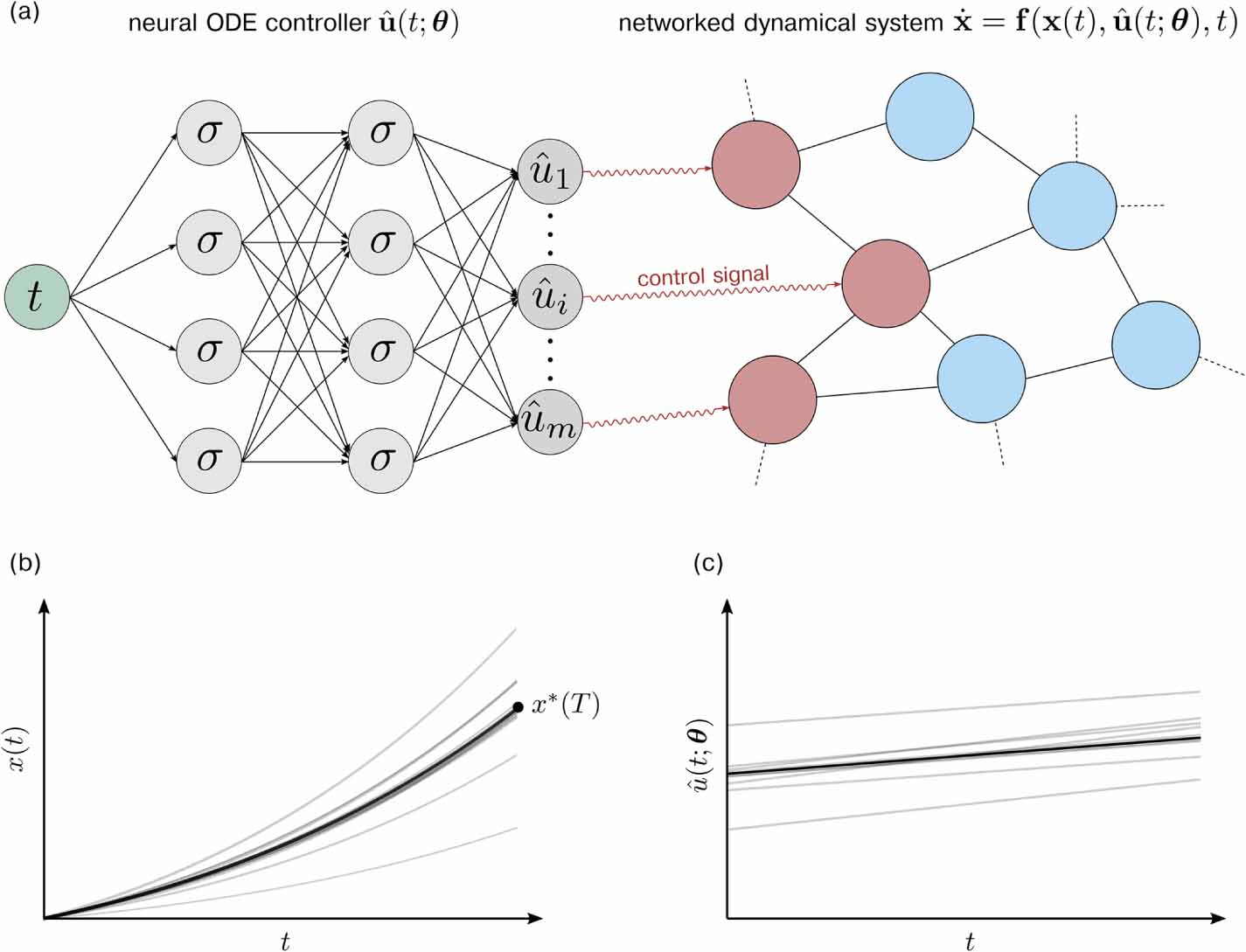
Figure C2. Loss landscapes for training with SD. Loss landscapes for training with Adam. Around a local optimum  obtained after 1000 training epochs, we set the neural-network parameters
  , where
  . (a), (d) The loss
  (see equation (20)) as a function of
 ![$\alpha\in [-0.4,0.4]$](https://content.cld.iop.org/journals/2632-2153/3/4/045004/revision2/mlstac92c3ieqn308.gif) , β = 0 (a) and
, β = 0 (a) and ![$\alpha,\beta\in[-0.4,0.4]$](https://content.cld.iop.org/journals/2632-2153/3/4/045004/revision2/mlstac92c3ieqn309.gif) (b). (b), (e) The MSE associated with the difference between
(b). (b), (e) The MSE associated with the difference between  and
and  ,
,  (see equation (43)), as a function of
 ![$\alpha\in [-0.4,0.4]$](https://content.cld.iop.org/journals/2632-2153/3/4/045004/revision2/mlstac92c3ieqn313.gif) (b) and
(b) and ![$\alpha,\beta\in[-0.4,0.4]$](https://content.cld.iop.org/journals/2632-2153/3/4/045004/revision2/mlstac92c3ieqn314.gif) (e). (c), (f) The control energy
(e). (c), (f) The control energy ![$E_T[\hat{u}]$](https://content.cld.iop.org/journals/2632-2153/3/4/045004/revision2/mlstac92c3ieqn315.gif) (see equation (1)) as a function of
(see equation (1)) as a function of ![$\alpha\in [-0.4,0.4]$](https://content.cld.iop.org/journals/2632-2153/3/4/045004/revision2/mlstac92c3ieqn316.gif) (c) and
(c) and ![$\alpha,\beta\in[-0.4,0.4]$](https://content.cld.iop.org/journals/2632-2153/3/4/045004/revision2/mlstac92c3ieqn317.gif) (f). The OC energy,
(f). The OC energy,  , is indicated by a dashed black line in panel (c). The neural network that we use in this example consists of 2 hidden layers with 5 ELU neurons each. Parameters are set to
  and
and  . We used SD to train NODEC and we set the learning rate to η = 0.1733. Initial weights and biases are set to 0.1.
Download figure:
Standard image High-resolution image
Figure C1 shows two and three-dimensional loss projections around a local optimum found by Adam. The local optimum is associated with a small loss, MSE, and control energy. Other surrounding local optima are not closer to OC solution.
For the same neural network and initial conditions, we observe in figure C2 that SD gets stuck in a local optimum that is associated with a larger MSE than the optimum found by Adam. Another optimum that is visible in the projections in figure C2 has a significantly smaller MSE and control energy than the one found by SD. However, in the shown example, SD converges toward a constant control approximation (see section 5.3) and not towards the local optimum that is closer to the OC solution