
Abstract
The work primarily focuses on increasing the efficiency of EV drive in electric two-wheeler by working on several aspects, such as modulating the vehicle's design, optimizing the control strategy, and increasing the speed range using a dual-motor approach. The dynamics of electric two-wheeler have been discussed with a mathematical vehicle model and further tuning of several aspects. Besides, this paper also introduces a novel Augmented Teaching and Learning based Optimization (ATLBO) technique designed exclusively to control BLDC motors for the electric two-wheeler vehicle. Besides, the designed technique has been implemented for the widely used commercial e-bike of Hero Company. Most two-wheeler electric motors are mounted on the rear side of the wheel, which has a limited speed range. Therefore, an analysis has been performed to increase the vehicle's speed range using a dual motor, from 45 km hr−1 to 62 km hr−1, proving to be a viable alternative to a single motor generally used in an electric bike. ATLBO technique has been designed against a conventional TLBO to optimize the proportional-integral-derivative (PID) controller for the speed control of a linear brushless DC (BLDC) motor. The proposed method has several advantages, including ease of implementation, a consistent convergence characteristic, and high computational efficiency. Furthermore, the literature has validated the merits of the presented novel control technique. The only disadvantage of using a dual motor is the initial cost, but the overall cost is moderated in the long-term usage for its augmented performance parameters. The performance parameters of the above technique are analyzed against other optimization techniques like conventional Teaching and Learning based optimization (TLBO), Particle Swarm Optimization (PSO). MATLAB/Simulink models the brushless DC motor and implements ATLBO, TLBO, and PSO algorithms. It has been found that the response obtained from ATLBO is comparatively much faster than other optimization techniques, which supports the motor for quick acceleration as well as more efficient in improving the step response characteristics such as rise time, settling time, and steady-state error in the speed control of a linear BLDC motor.
Export citation and abstract BibTeX RIS
1. Introduction
Adopting electric vehicles (EVs) is essential to revolutionizing the automotive sector through a sustainable approach. Optimized control of electric drive for high-performance parameters of EV is a critical factor in this regard. This includes the choice of motor, modulating its design and optimized control to suit EV requirements. Besides, there are some other constraints of two-wheeler EVs, such as limited energy storage of battery pack and their effective utilization, limited speed, limited range, high initial cost and the proper choice of electric motor [1, 2]. EVs utilize different types of the motor such as Induction Motor (IM) [3], Switched Reluctance Motor (SRM) [4], DC motor [5], Permanent Magnet Synchronous Motor (PMSM) [6], BLDC [7] etc. Among all these motors, IM and BLDC drive for EVs are widely used in a commercial vehicle. IM is cost-effective and rugged among all motors [8]. However, it lags in several performance characteristics like poor power factor, lower efficiency etc. In contrast, BLDC has several advantages over IM, such as higher efficiency due to the absence of rotor winding, smaller size due to high torque to weight ratio, low noise, better power factor and adequate dynamic response [7]. Considering all these benefits, BLDC is considered to be a potential choice for EVs [7–9]. The cost of the BLDC is high due to the additional use of a converter and controller. This can be affordable with precise control of the motor. This work discusses using BLDC motor for electric two-wheeler controlled through PID, optimized through a novel algorithm, which has been further implemented for Hero company-based EV bike.
Considering the control techniques of several motors for electric drives, industrial process control techniques have come a long way in the last decade. Neural control [10], fuzzy control [11] and adaptive control [12, 13] are just a few of the control approaches that have been investigated. The PID controller is the widely considered control technique among all these and is being extensively utilized in the industry due to its simple design and reliable performance for a wide range of operations. However, proper PID controller tuning is quite difficult due to its high order. Due to the simplicity and ease in the design of the PID controller, it is easy to implement smooth control of electric vehicles (EVs). However, the PID controller constant should be designed appropriately. The first method relied on Ziegler and Nichols' classical tuning rules [14], but this method has proven tough in determining optimal or near-optimal PID settings. such as particle swarm optimization (PSO) [15], artificial bee colony (ABC) [16], ant colony algorithm (ACO) [16], bat algorithm [17], and firefly algorithm [18] are being utilized to optimize the ID control method.
Evolutionary algorithms such as PSO, ABC, ACO, BAT algorithm are preferable to conventional optimization techniques such as incremental conductance [19], hill climbing [20], perturb and observe [21] because the fitness function for the parameter extraction problem is a multi-modal optimization problem. However, it has been discovered that using a genetic algorithm (GA) to solve the existing problems has a number of drawbacks, including slow convergence and deterioration of highly interaction fitness functions. Therefore, particle Swarm Optimization (PSO) has been used to solve parameter extraction problem due to the drawback of GA [22]. This method has proven to offer better results, such as correct PID controller constant. But, in this case, the no of iterations is increased, which may take longer computation time.
Teaching and learning-based optimization (TLBO) is another efficient, simple, intelligent optimization technique for solving various linear and non-linear large-scale problems. The TLBO algorithm has been used in a variety of sectors, including engineering design [23], medical disease diagnosis [24], and many other applications described in the literature [25] because it performs exceptionally well and requires no additional parameters. However, in the TLBO algorithm, a teacher (teacher phase) and two random students are selected (learner phase), which restricts the learner phase. In this work, the considered problem has been solved using an augmented version of TLBO, i.e. ATLBO algorithm. Furthermore, the response obtained from the ATLBO algorithm is found to be very suitable for the electric scooter. As in the case of an electric scooter or light vehicle, the transient behavior should be better so that it can easily pick up speed quickly. In case of a heavy vehicle, it need not require a transient response to be better rather, it urges a steady state behavior since it runs at constant speed mostly.
Besides, the work also analyzes utilizing dual motors against single motor in EVs. In general, the motor is linked to the rear wheel shaft through a transmission in the chassis-mounted topology. This particular transmission typically has set gear ratios. Depending on the motor specifications and required maximum vehicle speed and torque, the gear ratio ranges from 1:6 to 1:10. The size and efficiency of the in-wheel motor is increased significantly, because a classic mounted motor is used for low torque and high speed as compared to the in-wheel motor. The powertrain's overall efficiency is however decreased by the transmission, which is coupled in series with the motor and the rear wheel. In order to obtain the greater range, the battery size must be increased due to the decrease in efficiency. Another problem in the case of electric scooters is their speed range which is limited by the use of single motor. Because it can't go beyond its range due to transmission losses. The use of dual motors can reduce this problem.
This paper introduces a dual-motor approach aimed at enhancing the speed performance of electric two-wheeler vehicles (EVs) compared to those equipped with a single motor. In typical commercial electric scooters, a single motor is commonly employed. However, the proposed method involves substituting the existing single motor with an additional electric motor, albeit with a lower power rating. This modification is intended to enable higher speed operations, contributing to an overall improvement in the speed and efficiency of the electric two-wheeler. To validate the effectiveness of this dual-motor approach, the study utilizes a well-known electric scooter model, the Hero Electric Photon, which is widely recognized and commercially available.
This paper is divided into the following sections. Section II describes the vehicle modelling, in which different forces acting on the vehicle are described. Section III describes the mathematical modelling, transfer function and PID controller of BLDC motor. In section IV, optimization techniques are discussed, and an optimized value of the PID controller constant is found with the help of optimization techniques. The last section V describes the dynamical equation of the BLDC motor with EV and performs a dual motor analysis. Their result and analysis is discussed subsequently.
2. Electric vehicle modelling
The dynamics of any EV can be broadly classified into two aspects: a) vehicle dynamics and b) motor dynamics. These two dynamics are coupled via the transmission unit, comprising the gearing system. The vital parameters in modelling any vehicle dynamics are hill climbing angle, acceleration, road condition, and aerodynamic drag.
A vehicle model is shown in the figure 1 to describe the forces acting on the vehicle. The description of each force are as follows:
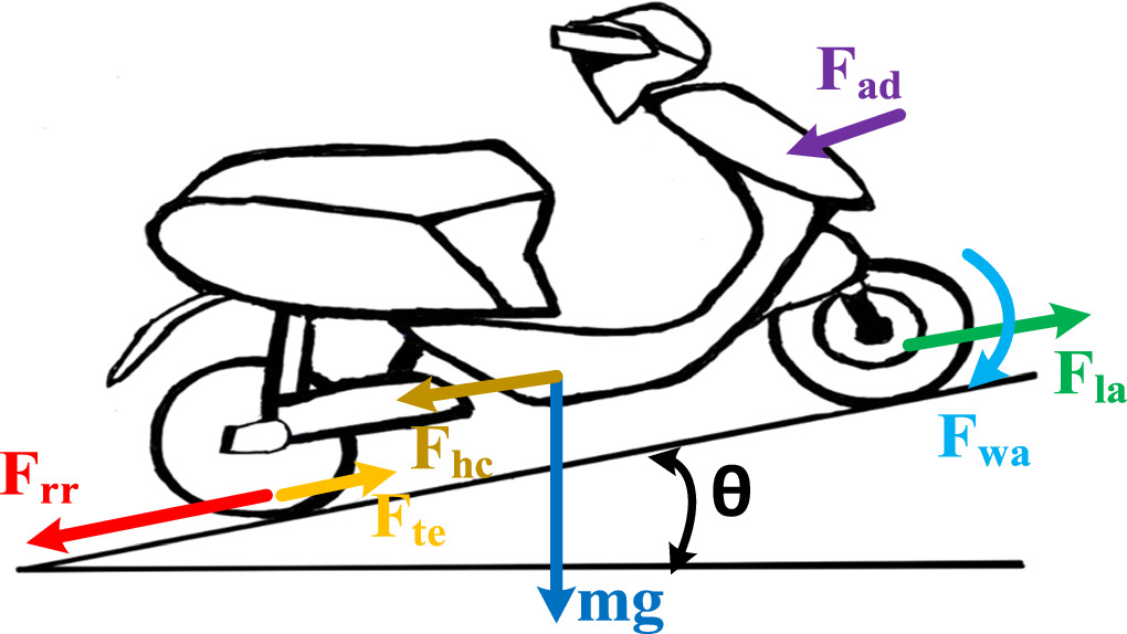
Figure 1. Forces acting on a vehicle [26].
Download figure:
Standard image High-resolution imageTractive Effort (Fte):- Tractive effort represents the force applied to the wheels that propels the electric two-wheeler forward. This force is generated by the electric motor and is responsible for overcoming resistive forces to ensure the vehicle's acceleration. Mathematically, Fte is the driving force exerted on the wheel.
Aerodynamics Force (Fad):- Aerodynamics force is the resistance exerted by the air against the forward motion of the electric two-wheeler. As the vehicle moves, it encounters air resistance, and (Fad) acts in the opposite direction, opposing the vehicle's forward movement. The magnitude of this force depends on factors such as the vehicle's speed and the shape of its body.
Rolling Resistance Force (Frr):- Rolling resistance force arises from the friction between the tires and the road surface. It is a resistive force that opposes the rolling motion of the wheels. Frr is influenced by factors like tire type, road conditions, and the load on the vehicle. This force is essential to consider as it affects the overall energy efficiency of the electric two-wheeler.
Hill Climbing Force (Fhc):- Hill climbing force is the resistance encountered when ascending an inclined road surface. Fhc is directly related to the incline of the road and plays a crucial role in determining the energy requirements for ascending slopes. It is a component that contributes to the overall resistive forces and influences the power needed for climbing inclines.
Linear Acceleration and Angular Acceleration Force:- Linear acceleration force Fla is associated with the acceleration of the electric two-wheeler in a straight line, contributing to changes in its translational motion. Angular acceleration force (Faa) is linked to the rotational acceleration, affecting the vehicle's turning or angular motion. Both forces represent the dynamic aspects of the electric two-wheeler's motion.
The motor gives a tractive effort (Fte) on the wheel, which is responsible for the vehicle's forward movement. This tractive effort is countered by different forces such as aerodynamics force (Fad ) which is applied by the air; rolling resistance force (Frr ) which is applied by the friction and hill climbing force (Fhc ) which is applied due to the inclination of the road surface. Nevertheless, the tractive effort overcome all these forces to accelerate the vehicle. The expression of all these forces is shown in equation (2).
Therefore, the tractive effort is given by-

Where Fla is linear acceleration force, Fωa is angular acceleration force. i.e.

Where 'μrr' is the rolling resistance with assumption of identical rolling resistance on the front and rear tires, 'm' is the total average mass, 'g' is the acceleration due to gravity, 'ρ' is the density of air, 'A' is the frontal area of scooter, 'Cd ' is the drag co-efficient, 'v' is the velocity of vehicle, 'I' is the moment of inertia of rotor of the motor, 'ηg ' is gear system efficiency, 'G' is the gear ratio and 'r' is the radius of the wheel.
Typically, the value of angular acceleration is much smaller than linear acceleration. So, the angular acceleration value may be ignored and consider only 5% of the linear acceleration value. i.e. increase the total mass by 5% [27].
3. Brushless DC motor
The Electric Motor plays a very important role in the EVs drive. BLDC motor is one kind of permanent magnet synchronous motor. A permanent magnet motor is divided into two categories depending upon the wave shape of the induced emf. If the induced emf wave shape is sinusoidal, it is known as Permanent Magnet Synchronous Motor. And if the induced emf's wave shape is trapezoidal, it is known as a Permanent Magnet brushless DC motor. Since DC motor is an essential candidate for EV due to its prominent speed-torque characteristics but it suffers problems from brushes and commutator. It requires high maintenance, which is why a brushed DC motor is not used in EV. But, in case of the brushless motor this problem is solved but its torque–speed characteristics is similar to the DC motor. This is an important reason that it is widely used in EV and HEVs applications. This motor has many advantages; the overall volume and weight are significantly low for a given output power, i.e., high power density; higher efficiency, noiseless operation, long operating life, high-speed ranges, and heat dissipation is very good to the surroundings [28].
The mechanical rectifier and brushes are used for commutation in the DC motor. On the other hand, the BLDC motor uses Hall Effect sensors rather than mechanical rectifiers and brushes. Coils are stators in BLDC motors, whereas permanent magnets are rotors. The magnetic fields created by stators cause the rotor to rotate. The hall effect sensors detect the rotor position. As a result, BLDC motors do not require brushes since they use permanent magnets instead of coils in the armature.
Mathematical modelling of BLDC and corresponding control strategy are considered in this section for E-bike. Figure 2 shows the control strategy of the BLDC motor using a PID controller optimized through novel algorithm ATLBO along with PSO and TLBO. A PID controller is applied in series with the motor. This PID controller is optimized by different optimization techniques such as PSO, TLBO and ATLBO. Since the transfer function of the BLDC motor is obtained with respect to output as a speed (rad/sec) and input is speed. So, as a reference, a speed command is applied, which will be our desired output. The characteristics of output is shown in section IV.

Figure 2. Block diagram of BLDC motor with PID controller.
Download figure:
Standard image High-resolution image3.1. Mathematical modelling
The mathematical equations of the BLDC motor can be represented with the voltage equation as –

The back emf of the motor is proportional to the speed of the motor i.e.

The electromagnetic and load torque equations of the BLDC motor is given by –


Where Vi
(t) is the applied voltage, i(t) is the stator current of the motor,  is the motor speed, eb(t) is the back emf of the motor, R and L are the stator resistance and inductance, respectively, T is the motor torque, B is the viscous coefficient, J is the moment of inertia, Kb
is the back emf constant, and Kt
is the electromagnetic torque constant. The parameters of the BLDC motor are given in table 1, which is to take to find the motor's transfer function.
is the motor speed, eb(t) is the back emf of the motor, R and L are the stator resistance and inductance, respectively, T is the motor torque, B is the viscous coefficient, J is the moment of inertia, Kb
is the back emf constant, and Kt
is the electromagnetic torque constant. The parameters of the BLDC motor are given in table 1, which is to take to find the motor's transfer function.
Table 1. Specifications of BLDC Motor used in this study.
| Sl no | Parameters | Value |
|---|---|---|
| 1. | Rated terminal voltage | 24V |
| 2. | Rated current | 8.5A |
| 3. | Rated Power | 200W |
| 4. | Rated Speed (Ns) | 2300 rpm |
| 5. | Per phase resistance (R) | 27.739 mohm |
| 6. | Per phase inductance | 40 μH |
| 7. | Back-emf constant (Kb) | 9.133 V/krpm |
| 8. | Torque Constant (kt) | 0.087248 Nm/A |
| 9. | Rotor inertia (J) | 0.0031095 Nms2 |
3.2. Transfer function
To find the transfer function of the motor, the Laplace Transform of the above equations have been taken. The above equations obtained after Laplace Transform are as


From equations (7), (8) and (11),
Therefore, the transfer function of the BLDC motor is given as

3.3. PID controller
Since the PID controller has a simplicity to design and due to its robustness, reliability and easy tuning, it is widely used in industrial applications. PID controller is commonly called as proportional (P), integral (I) and derivative (D) controller. The proportional controller is used to decrease the error of the system. It reduces the error by a factor of its gain. But this can't make an error equal to zero. For that, an Integral controller has been used. By proper selection of an integral controller, a steady-state error can be almost reduced to zero. It also improves the response time of the system. The derivative controller decreases the system's overshoot but generally increases the system's response time [29]. A block diagram of the PID controller is shown in figure 3. By proper tuning of the PID controller, the desired performance of the motor can be optimized. For the optimum tuning of the controller, three different optimization techniques, including an Augmented TLBO, have been implemented. This article compares the result obtained from ATLBO with optimization techniques TLBO and PSO.

Figure 3. PID controller.
Download figure:
Standard image High-resolution imageThe mathematical equation of the output in S-domain of PID controller can be given as

The time domain output of the controller is

Where, KP = gain of proportional controller
KI = gain integral controller
KD = gain derivative controller.
4. Optimization techniques
The PID controller used for the BLDC motor can be tuned using several optimization methods. This work proposes a novel optimization technique, i.e. ATLBO, and corresponding results are compared with conventional techniques such as PSO and TLBO.
Optimization is a method of determining a solution to a problem for minimizing or maximizing an objective function within the domain containing acceptable values of variables. While also meeting certain constraints. Various solutions might satisfy the requirements and maximize or minimize the objective function. They are known as acceptable solutions. And the best solution among them is referred as the optimal solution to the problem. Three optimization techniques have been implemented to find the controller gain and compare its solution. When a system reaches its intended performance goals or runs as efficiently as possible, it is said to be in an optimal control state. The goal of the optimization procedure in the context of our study is to identify the ideal PID controller parameters that satisfy predetermined performance standards and minimize a cost function. A quantitative indicator of system performance, the cost function takes error reduction, stability, and responsiveness into account[28]. The following objective function is taken into account in this study when tuning the PID controller.

Where, Mp is overshoot, tr is rise time, ts is settling time, Ess is steady state error, β is weighting factor.
4.1. Particle swarm optimization (PSO)
Kennedy and Eberhart initially introduced the PSO approach in 1995. It's a type of evolutionary computing method. Adaptation, a concept derived from social-psychological philosophy, has been effective in dealing with non-differentiability issues and nonlinearity issues with a large number of optima and a high degree of dimensionality. This optimization method is based on swarm studies such as bird flocking and fish schooling. However, the computation time is less, and it necessitates the use of some memory [30].
Birds obtain food via flocking, according to the findings of a study on a flock of birds (not by each individual). The finding leads to the conclusion that the flocking shares all information. Furthermore, each individual's (agent) behaviour is dependent on the groups' permitted behaviour patterns, such as customs and other behavior patterns, depending on each individual's experience. according to observations of human group behavior. PSO was created mostly by simulating a flock of birds in two-dimensional space. The XY-axis represents each agent's location, while Vx (x-axis velocity) represents their velocity (displacement vector). The location and velocity information are used to change the position of the agent [15].
Each particle keeps track of its positions in the challenge space, which are linked to its most recent best solution (evaluation value). This is referred to as pbest. The other best value monitored by the particle swarm optimizer's global version is gbest, which represents the best value and its global position as determined by any particle in the group. At each time step, the velocity of each particle changes towards its pbest and gbest positions, according to the PSO concept.
The ith particle, for example, is represented as xi = (xi,1, xi,2,...xi,g). pbesti = (pbesti,1, pbesti,2,..., pbesti,g) returns the ith particle's best previous position. Among all the particles in the group, gbestg is the best particle index. Vi = (vi,1, vi,2,..., vi,g) represents the velocity of ith particle. Using the current distance and the velocity from Pbesti,g to gbestg, each particle's modified velocity and location can be determined as stated in the formula below [31].


i = 1, 2, ..., n
g = 1, 2, ...., m
where,
n number of particles in a group;
m number of members in a particle;
t pointer of iterations (generations);
 velocity of particle j at iteration t,
W inertia weight factor;
c1, c2 acceleration constant;
Rand(),Rand() random no between 0 and 1;
 current position of particle i at iteration t;
pbesti best position of the ith particle
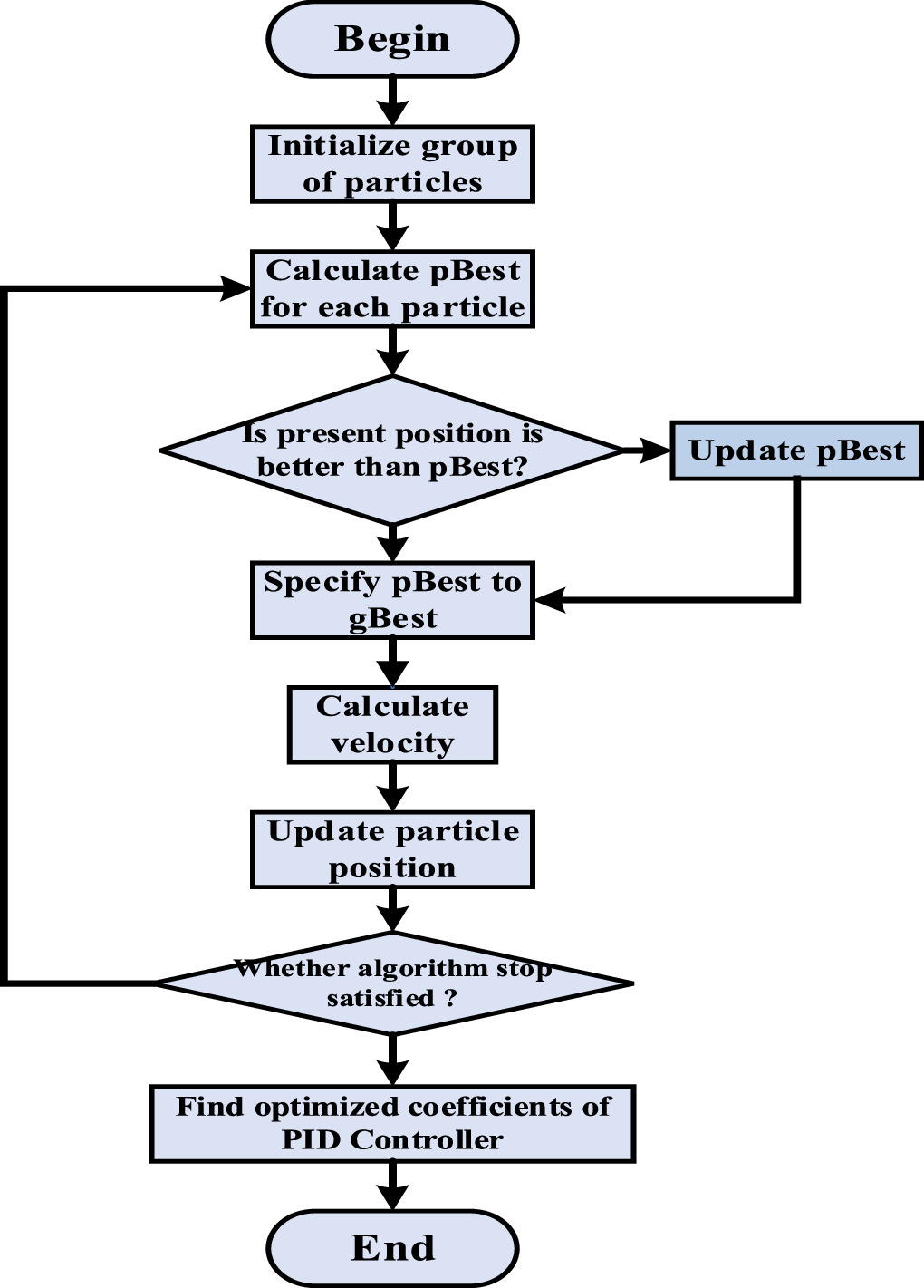
gbest is the best particle among all the particles in the population. The whole process of this Algorithm is represented in flow chart as shown in figure 4.

Figure 4. Flow chart of PSO technique.
Download figure:
Standard image High-resolution image4.1.1. Result and analysis
PID controller implemented for BLDC motor is shown in figure 5. The PID controller has been optimized using PSO algorithm, and the result obtained with an optimized value of controller is shown in the figure 6.
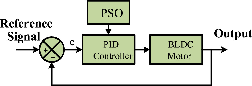
Figure 5. PSO based optimal PID control.
Download figure:
Standard image High-resolution image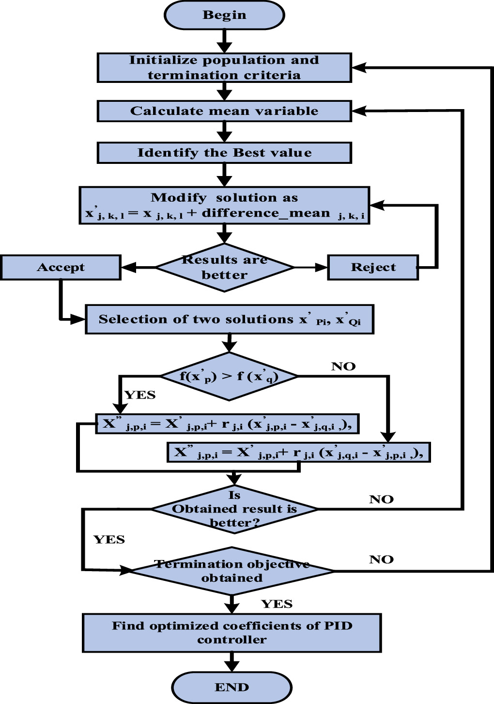
Figure 6. Flow chart of TLBO technique.
Download figure:
Standard image High-resolution image4.1.2. Step response of the motor
A step input is applied on the BLDC motor. The step response of the motor is shown in the figure 9. The parameters obtained in the step response is shown in the table 2. The rise time obtained from the motor is around 25.5 μsec. The settling time is 48 μsec, which is inferior to the other result obtained from ATLBO and conventional TLBO techniques. But for this particular value of PID controller constant, the peak overshoot and undershoot is zero.
Table 2. PID controller constant parameters of PSO, TLBO and ATLBO.
| Controller constant | PSO | TLBO | ATLBO |
|---|---|---|---|
| Kp | 27.4358 | 11.2298 | 9.66998 |
| KI | 30.133 | 17.27115 | 16.74595 |
| Kd | 0.125 | 0.2663 | 0.2715 |
The parameter characteristics of the step response of the motor with optimized controller constant obtained from the PSO technique is shown in the table 2 and the step response characteristics of the motor with optimized controller constant is shown in table 2. These response characteristics is obtained by MATLAB simulation.
4.2. Conventional teacher-learning based algorithm
It is an algorithm inspired by the teaching–learning of teachers and students proposed by Rao et al in 2011. It's based on the influence of a teacher on students in a classroom [32]. This Algorithm defined two main types of learning: (1) direct learning by a teacher (teacher phase) and (2) interacting among learners (learner phase). A population of learners is included in this optimization technique. The optimization problem's separate design variables are the various subjects given to the learners and the various subjects. The fitness value of the optimization issue is equivalent to the learner's outcome. The teacher is seen to be the best solution for the entire population. The design variables are considered as the parameters of the objective function in the given optimization problem. The optimal solution is the objective function's best value. This Algorithm's entire operation is explained below
- a.Teacher Phase
In this step of the Algorithm, the most educated individual is taken into account, which is the teacher. In this teacher phase, the teacher aims to improve the average performance of the students in the class in the topic he is teaching. The mean performance of the class that all depends on the quality of the teacher. The total no of learners is considered as the population size and no of subject is considered as design variables. In this step of the Algorithm, the most educated individual, the teacher, is taken into account. During this phase, the teacher aims to improve the average performance of the students in the class in the topic he is teaching.
 is the ith iteration optimum solution. The value of f(
 ) is minimum. The optimum solution is
  The mean result
  is calculated in the next step for the newcomer in any concerned subject.
The design goal of improving the system's mean performance disparity, as previously described, may be expressed as follows:

The best learner of the subject is x j, kbest, i and mean is varied by the factor tf. The random value of ri,j is varied between 1 to 2 and it is represented in equation (14). The Algorithm uses the following equation to generate the value of tf. It is not the value of a single parameter that is supplied to the input -

The existing solution is updated with respect to difference mean, according to the following formula with respect to the mean difference in the j, k, i, teacher phase:
- b.Learner phase
It is the next step of the Algorithm, in which learners engage with one another to enhance their knowledge. The learners acquire knowledge from other learners who have more knowledge. Let the total population size is n. select P and Q two learners randomly such that

The entire process of TLBO algorithm is represented in the form of flow chart as shown in figure 6.
4.2.1. Result and analysis
The PID controller-based simulation model is implemented in the figure 8. The PID controller constant value is found with the help of the TLBO algorithm. And the result obtained with the optimized value of the controller is shown in figure 7.
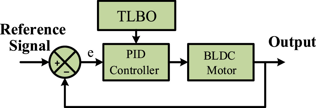
Figure 7. TLBO based optimal PID control.
Download figure:
Standard image High-resolution image
Figure 8. ATLBO based optimal PID control.
Download figure:
Standard image High-resolution image4.2.2. Step response of the motor
A step input is applied on the BLDC motor. The step response of the BLDC motor is shown in the figure 9. The PID controller constant obtained from TLBO is shown in the table 2. The rise time obtained from the motor is less, and it is around 12 microseconds. In the step response, there is no overshoot, and undershoot is obtained. This response is obtained for the optimized value of the PID controller constant that is given in table 2.

Figure 9. Step response of BLDC motor with different optimization techniques.
Download figure:
Standard image High-resolution image4.3. Augmented TLBO (ATLBO) techniques
In the conventional TLBO teaching and learning phase is conducted by one teacher (current best solution) and two randomly selected students (individuals), respectively. This imposes some restrictions on the search and use of TLBO search. Therefore, this work is required to be Augmented. So, a new version of TLBO is suggested. The proposed adaptive learning-based Algorithm updates the learner phase. In the teacher phase, one teacher is assigned to each subject, while in the learning phase, a learning scheme of four students is added to increase the convergence rate.

The proposed TLBO is represented through the Algorithm-
Proposed TLBO Algorithm
Input: Maximum number of iterations (max), population size (nP)
Output: xbest, fbest
Main Algorithm
| 1 Set up the population and the values of their objective functions. |
| 2 For i = 1 to max |
| 2.1 Select the best solution, xbest, fbest and define xteacher = xbest |
| (Teacher Phase) |
| For j = 1 to np |
| 2.2 Update the population using equation (15) |
| 2.2.1 Calculate the value of the objective function. |
| 2.2.2 Make a greedy selection |
| Learner Phase |
| For j = 1 to np |
| 2.3 update the population using equation (17) |
| 2.3.1 Calculate the value of the objective function |
| 2.3.2 Make a greedy selection |
| End. |
| 3. End |
4.3.1. Result and analysis
A simulation-based model is shown in figure 8, where PID controller constant value is found out by the ATLBO technique. The performance characteristics of the BLDC motor are shown in the figure 9. Performance characteristics of BLDC motor have better response and is quite suitable for a vehicle with a good transient response.
4.3.2. Step response of the motor
A step input is applied on the BLDC motor. The step response of the motor is shown in the figure 9. The PID controller constant obtained from ATLBO technique is shown in table 2, and parameters obtained from step response is shown in the table 2. The rise time that has been obtained of the motor is very less, and it is around 11.63 μsec which is the best result as compared with the other optimization techniques. Similarly settling time of the system is also Augmented, and it is better than other optimization techniques. Furthermore, there is no overshoot in the step response, and undershoot is obtained, which is similar to others.
4.4. Comparative analysis
The results obtained in this work for BLDC motor has been compared and analyzed with different works from the literature. The related comparative study is shown in the table 3. Jigang et al [33] have performed the speed control with PI controller optimized with the modified differential evolution algorithm. The maximum overshoot obtained by the proposed Algorithm is 2.47%, whereas rise time and settling time are 14 ms and 31 ms under sudden load change. Similarly, by using a genetic Algorithm, an optimal PID control of the BLDC motor is performed by Ibrahim et al [34]. In this work, a PID controller is being utilized using conducted integral absolute error (IAE) criterion and integral square error criterion. The response characteristics with IAE is shown in the comparison table. The rise time and settling time is 51.1 μsec and 91.1 μsec, respectively. Kommula et al [35] have utilized modified firefly-based PSO for fractional order PID controller to control BLDC motor. The result shown in the comparison table is with respect to a speed of 2000 rpm and 1.5 Nm torque from their work [35]. In this condition, peak overshoot and settling time result are 0.7% and 0.254 sec, respectively. In the works by Wang et al [12] and Shuraiji et al [13] an adaptive fuzzy PID and fuzzy PID controller are discussed, respectively, for the control of BLDC motor. In the work by Wang et al [12] settling time and peak time are 40 ms for a speed of 2997 rpm, and the steady-state error is 2.9 rpm. Whereas one by Shuraiji et al [13], rise time is 19.53 ms, peak overshoot is 1.531%, and undershoot is 11.924%.
Table 3. Comparative analysis with PSO, TLBO, ATLBO and other literature.
| Algorithm | Rise time | Settling Time | Peak Time | Peak Overshoot | Peak Undershoot | Peak | Steady State Error | |
|---|---|---|---|---|---|---|---|---|
| PSO PID | 25.492 μsec | 48.0 μsec | 108.16 μsec | 0 | 0 | 0.994 | 0.006 | This work |
| TLBO PID | 11.892 μsec | 21.885 μsec | 56.268 μSec | 0 | 0 | 0.9963 | 0.0037 | This work |
| ATLBO PID | 11.663 μsec | 21.456 μsec | 55.192 μsec | 0 | 0 | 0.9964 | 0.0037 | This work |
| Differential evolution-based PI | 0.014 sec | 0.031 sec | ∼ | 2.47% | ∼ | ∼ | 0 | [33] |
| GA based PID | 51.1 μsec | 91.1 μsec | ∼ | 0 | ∼ | 1 | 0 | [34] |
| Modified firefly-based PSO PID | ∼ | 0.254 sec | ∼ | 0.7% | ∼ | ∼ | ∼ | [35] |
| Adaptive fuzzy PID | ∼ | 40 ms | 40 ms | ∼ | ∼ | ∼ | 2.9 rpm | [12] |
| Fuzzy PID | 19.53 ms | ∼ | ∼ | 1.531% | 1.788% | ∼ | ∼ | [13] |
From all these works considered for the comparative study, it can be concluded that the result obtained from the proposed ATLBO in this work is comparatively more optimized. Among all the works from the literature, the minimum overshoot of 0.7% is there, whereas with ATLBO, there is no overshoot. Similarly, the minimum settling time obtained is 91.1 μ sec, whereas with ATLBO, this settling time is even much smaller i.e. 21.456 μ sec. The comparative response of ATLBO, TLBO and PSO is shown in figure 12, and the comparative value of PID controller constant is shown in the table 2. This comparative analysis shows that ATLBO provides the better and optimized value of the controller constant, which supports fast response in vehicle acceleration.
5. Vehicle dynamics of electric bike
In this section, vehicle dynamics for the Electric bike have been analyzed for BLDC used in this study, and further the study has been analyzed for Hero Photon E-bike using the experimental parameters for the BLDC used in that particular bike. In table 4, parameters considered for the BLDC motor is taken in the first part of this section, and the parameters of the BLDC motor used in the hero electric bike, as shown in table 4 is taken in the second part of this section. Furthermore, dual-motor has been suggested for Hero Photon E-bike, and a corresponding study has been included. The 200 W electric motor is strategically incorporated as part of a dual-motor system, working in conjunction with the existing, stronger electric motor utilized in the Hero electric bike. Unlike the primary motor, the 200 W motor is not engaged during the initial acceleration phase but comes into play during specific running conditions.
Table 4. Motor parameters considered for the design of electric scooter.
| Sl no | Parameters | Our motor | Motor used in hero-electric photon |
|---|---|---|---|
| 1. | Motor type | BLDC | BLDC |
| 1. | Motor power | 200 W | 1200 W |
| 2. | Top speed | 62 km h−1 | 45 km h−1 |
| 3. | Wheel diameter | 30.48 cm (Front and rear) | 25.4 cm (Front and rear) |
| 4. | Average mass of scooter | 110 kg | 95 kg |
| 5. | Passenger mass | 65 kg | 65 kg |
| 6. | Frontal area | 0.7 m2 | 0.7 m2 |
| 7. | Drag co-efficient | 0.5 | 0.5 |
| 8. | Rolling resistance (μrr) | 0.007 | 0.007 |
| 9. | Gear ratio | 2:1 | 2:1 |
5.1. Force analysis for BLDC motor considered in this study
The tractive effort of the electric motor can be found with the help of equation (2). After putting all the parameters of the BLDC motor given in the table 4 the tractive effort is obtained as

To obtain the motor's velocity characteristics with respect to time, two cases have been considered i.e. when the motor is going to start and when the motor is running. At the time of starting motor needs maximum torque and when the motor is running in running mode, this torque should fall with respect to speed. The maximum torque produced by the motor can find out as-Since

Where, E is the electromotive force i.e. a voltage induced in the winding, Km is the motor constant, φ is the magnetic flux and N is the rotational speed in rpm. Therefore,

Therefore, maximum torque while starting is given by,

Since, the maximum possible value of current is up to 4 to 5 times the rated current for up to a few seconds. i.e. Imax = 40A is taken at the time of starting. Therefore, Tm is equal to 4 N-m. the tractive effort is given by the formula

Therefore, equation (18) becomes
Therefore,

while in running condition, it follows

i.e.

substitute T in equation (22) and finding tractive effort of the vehicle. Therefore, equation (18) is obtained as

Solving above equations (23) and (25) by MATLAB coding and speed versus time characteristics have been obtained as shown in the figure 10.
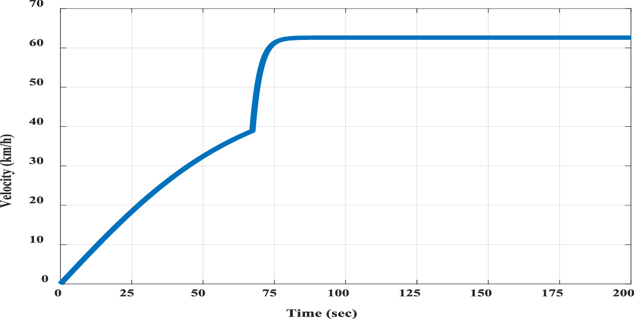
Figure 10. Speed-time characteristics of BLDC motor.
Download figure:
Standard image High-resolution imageThe starting torque of the BLDC motor is 4.0 N-m. At starting around the torque is being constant and after that torque is inversely proportional to speed such that power of the motor will be constant. After achieving speed of around 40 km h−1, the torque is further reduced due to the rise in speed. The final torque of the BLDC motor at its peak speed is around 0.9 N-m. And this torque remains constant at steady state. The torque characteristics of the BLDC motor is shown in the figure 11. The electric motor's speed versus time dynamic equation shows a sudden rise in responsiveness. This behavior can be ascribed to a number of variables, including external conditions, control inputs, and system dynamics. The motor may go from a lower to a higher operating mode as a result of shifting control signals or load conditions, which could account for the abrupt increase in response.

Figure 11. Torque characteristics of BLDC motor.
Download figure:
Standard image High-resolution imageNow, the inclination force acting on the vehicle body can also be considered. The inclination force is given by the equation

Two different inclination angles i.e.  have been considered.
So, the inclination force at  is Fhc
= 149.625 N and at
is Fhc
= 149.625 N and at  is Fhc
= 298.11 N. So, equation (25) can be modified, and it is equal to
is Fhc
= 298.11 N. So, equation (25) can be modified, and it is equal to

And

By, solving equations (23), (26) and (27), results at different inclinations can be obtained. The result is shown in the figure 12.
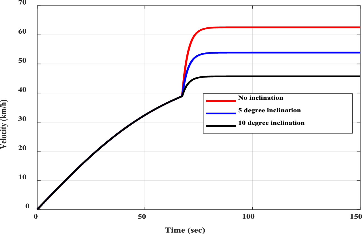
Figure12. Speed-time characteristics of BLDC motor with inclination.
Download figure:
Standard image High-resolution image5.1.1. Result analysis
The speed-time characteristics of BLDC motor, when used in the vehicle, are shown in figure 10. In this characteristic the initial acceleration is not good, and the initial torque is not sufficient to start the vehicle. It takes around 25 s to reach a speed of 20 km hr−1. But, in the running condition, when it reached to around 40 km hr−1, it had quick acceleration. And it takes only a few seconds to accelerate the vehicle from 40 km hr−1 to 60 km hr−1. That means this motor, a 200W motor is is not suitable for starting the motor, but it is suitable for the running condition. According to the speed-time characteristics, it has an application towards electric scooters. The speed time characteristics at the running condition at different inclinations have also been found. The force applied by the BLDC motor is sufficient to accelerate the vehicle in case of inclination also.
In the next part, Hero electric photon bike has been considered to find it's speed-time characteristics first, and later on, a solution to improve its top speed by the addition of one additional motor has been devised whose torque-speed response and control have been discussed earlier.
5.2. Force calculation for BLDC motor used in 'Hero Electric Photon' electric scooter
The tractive effort is calculated by the equation (2). With the use of hero electric photon electric motor parameter listed in table 4, the total tractive force is found out as

Here also if speed-time characteristics of motor have to be obtained, two cases can be considered. First at the time of start and second when the vehicle is in running condition. At the time of starting, it has to apply maximum torque that is calculated in a similar way as in case of first motor.

In this case the maximum possible value of current 213 A, only for few seconds since it has large rating machine compared to first motor. Therefore, the maximum torque is equal to 66.56N-m. Therefore, tractive effort is equal to

Therefore, equation (28) becomes
Therefore,

While in running condition, it follows equation (24). Therefore, it is equal to –

substitute 'T' in equation (29) and finding tractive effort of the vehicle. Therefore, equation (28) is obtained as –

Solving above equations (30) and (31) by MATLAB coding and speed versus time characteristics has been obtained as shown in the figure 13.
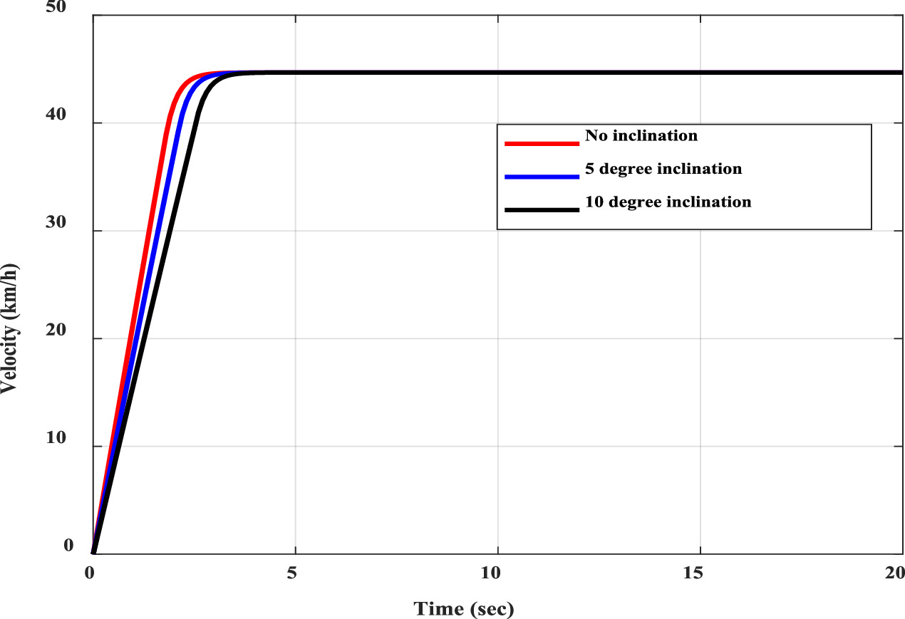
Figure 13. Speed time characteristics of hero electric photon electric scooter with inclination.
Download figure:
Standard image High-resolution imageNow, the inclination force acting on the vehicle body can also be considered. The inclination force is given by the equations -

Here also, two different inclination angles, i.e.  can also be considered.
So, the inclination force at  is Fhc
= 136.8 N and at
is Fhc
= 136.8 N and at  is Fhc
= 272.558 N. So, equation (30) can be modified, and it is equal to
is Fhc
= 272.558 N. So, equation (30) can be modified, and it is equal to

And

Solving equations (31)–(33) results at different inclinations can also be obtained. The result is shown in figure 13.
The starting torque of the hero electric photon electric scooter is 66.56 N-m. At starting up to 0.3 sec the torque is being constant and after that torque is inversely proportional to speed such that power of the motor will be constant. After achieving peak speed, the torque becomes constant and it is equal to 7.32 N-m. The torque-speed characteristics of the hero electric photon electric scooter is shown in the figure 14.
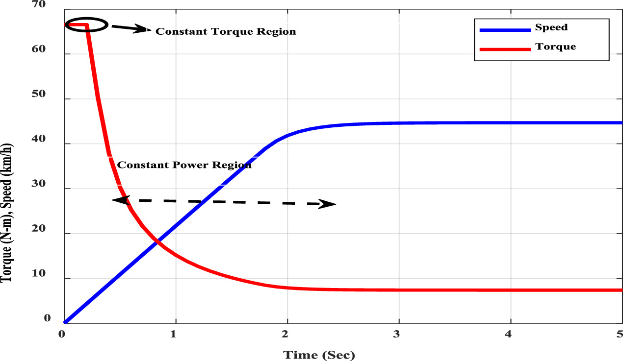
Figure 14. Torque-speed characteristics of hero electric photon electric scooter.
Download figure:
Standard image High-resolution image5.2.1. Result analysis
The hero electric photon electric scooter's speed-time characteristics are shown in figure 13. In this characteristic, the initial acceleration is good. It has quick start. It achieves 45 km hr−1 within 3 sec. But its maximum speed is 45 km hr−1, also mentioned in the specification of the hero electric photon scooter [26]. That means it is very suitable for electric scooters but cannot go beyond 45 km hr−1 speed range. Therefore, it has a limited speed range.
In the case of a light vehicle like an electric scooter, electric car quick acceleration and deacceleration is required. For this, its transient response has to be good. The transient response of both motors is shown in figures 10 and 13. The second motor used in the hero electric photon scooter has better transient characteristics than the motor used in this paper. Speed range of more than 45 km hr−1 with the use of both motors. i.e. can also be obtained. In the case of the dual motor, the requirement of both, i.e. good transient response or high initial acceleration and high-maximum speed, can be fulfilled. The characteristics of the dual motor is shown in figure 12.
In the above characteristics shown in figure 15, it is clearly understood that the it has very quick acceleration and if this electric scooter need to go in the high-speed range, then it has to switch to another motor. Then the overall speed of the motor is increased. The motor used in the high-speed region requires less torque, so it need not require more power. So, the battery's energy can be saved, and the distance range of the vehicle can be increased with one charge of the battery. The motor which is used to start i.e. which produces high initial torque has to mount in the rear wheel, and the motor used for speed greater than 45 km hr−1 is mounted in the front wheel because it need not require high torque to drive the vehicle. The above discussion is for the zero-degree inclination. If any inclination is present, then a hill climbing force is required to drive the vehicle. There are two inclination angles taken, and the result is found. The following result is shown in figure 12. It can be shown that motor acceleration is also quite good in the case of inclination. That means the hero electric photon scooter is suitable for starting and running conditions with and without inclination. However, for the performance of the electric bike highly depends on the voltage and current associated with the electric motor. Voltage is proportionate with the speed and the current is proportionate with speed and load [36].

Figure 15. Speed-time characteristics of dual motor.
Download figure:
Standard image High-resolution image
6. Conclusion
In this work, the BLDC motor with PID controller is tuned by optimization techniques, including a novel technique ATLBO, for Electric vehicle applications. This BLDC motor is suitable for the use of an Electric scooter at high speed. The performance parameter obtained from ATLBO is better than the other optimization techniques utilized in this work, such as PSO and TLBO. Besides, results are compared with the works from literature, and work is found to be suitable for EVs, particularly E-bikes. The experimental results from the literature verified that the proposed scheme. Since two motors of different power ratings are used, the overall system's speed range and efficiency is increasing. Motor with a higher rating is connected to the rear wheel because an electric scooter needs more starting torque while starting. The motor with less power rating is connected with the front wheel, which is used to boost the speed after the start of the motor. Therefore, in the case of the dual motor, the speed range of the hero electric photon scooter can be increased from 45 km hr−1 to 62 km hr−1, and the distance can also be increased with one charge of battery because of the less power-rated motor is used in the high-speed region. Their control is also augmented with ATLBO optimization techniques because its transient response obtained from ATLBO techniques is better than conventional TLBO and PSO. This work can be a remarkable contribution towards upgrading the current EVs' two-wheelers in particular
Acknowledgments
The authors acknowledge the Department of Science and Technology (DST), Govt. of India for the financial assistance provided under DST SERB Project (File No. SRG/2021/002110) to carry out the present work. Dr Amitesh Kumar would like to thank DST SERB for providing a Start-up Research Grant for this project to conduct research at NIT Patna. Mr Rajnish Kumar would like to thank the Ministry of Education and NIT Patna for the research fellowship. The authors are thankful to NIT Patna for providing research facilities.
Data availability statement
The data cannot be made publicly available upon publication because they are not available in a format that is sufficiently accessible or reusable by other researchers. The data that support the findings of this study are available upon reasonable request from the authors.