

Abstract
A dual-band 8 × 8 multiple-input-multiple-output (MIMO) PIFA antenna that operates in the sub-6 GHz spectrum for 5G and WLAN mobile terminals is presented. The eight elements of the MIMO antenna are formed by using an L-slotted PIFA antenna, an L-shaped parasitic element, and a 2D rectangular open-ended ring parasitic structure that is printed next to the L-shaped parasitic element. In this article, we first proposed an ultra-thick PIFA antenna element to work in the 3.4-3.8 GHz 5G band and the 5.15-5.85 GHz WLAN band, adopting a new method that can provide dual-band behavior with wide bandwidth. Then, the final antenna element is used to design an eight-port MIMO antenna system, and the results show good MIMO performance in terms of envelope correlation coefficient (ECC), diversity gain (DG), mean effective gain (MEG), and multiplexing efficiency (ME).
Export citation and abstract BibTeX RIS
1. Introduction
The use of MIMO technology in wireless communication systems has become one of the core of several emerging wireless standards and a viable solution to increase the channel capacity and improve the spectral efficiency without increasing the bandwidth [1]. In a Rayleigh fading channel with a signal-to-noise ratio (SNR) of 20 dB, the value of the capacity upper limit of an ideal eight-element MIMO system can attain 46 bps/Hz. Whereas for a two-element MIMO system, it is 11.5 bps/Hz [2]. Consequently, by using multiple antennas on both the transmitting and receiving ends, higher capacity and data rates can be achieved. Unlike 4G, which requires two to four antenna elements, at least six to eight antenna elements are needed to meet the requirement of 5G in mobile terminals [3]. However, taking into account the mutual coupling will degrade the performance of the MIMO system. Integrating multiple antennas within a limited space in mobile devices is a serious challenge since the electrical wavelengths in these frequency bands are much larger compared with the millimeter-wave (mm-wave) frequency bands.
On the other hand, since the World Radio Communication Conference (WRC-15) has allowed the allocation of the band 3,4-3,6 GHz for 5G mobile communications in 2015, numerous single-band MIMO antennas have been designed [4–9], including MIMO antennas that have been designed to operate in the 3.4-3.8 GHz band. Not to mention that the unlicensed wireless wide area network (WLAN) spectrum is considered a promising solution to meet the ever-growing mobile broadband data traffic demands, with the condition of ensuring a friendly coexistence between the 5G band and other wireless systems [10]. Therefore, designing MIMO antennas in these bands is necessary to meet high throughput requirements.
Planar Inverted F-antennas (PIFAs) are attractive antennas for mobile communications due to their omnidirectional radiation pattern and ability to enable dual-band properties by adding slots to the radiating plates. However, they suffer from a narrow bandwidth, and a wider bandwidth can only be achieved by increasing the height of the PIFA, which does not meet the compact requirements of modern communication systems. Some techniques have been proposed to enhance the bandwidth, such as changing the width of the feed plate [11], etching slots in the ground plane [12] and adding parasitic elements [13]. Further, several recent studies have used PIFAs for 5G sub-6 GHz MIMO applications in mobile terminals. A two-port, two-element dual-band MIMO antenna with a 7.7 mm height has been designed in [14] to support the 4G band (2.5-2.7 GHz) and 5G band (3.4-3.8 GHz). Here, meandered slots are used to attain dual-band behavior and a parasitic element to enhance its bandwidth. In [15], a four-port, two-element single-band MIMO antenna having a height of 3 mm and two rectangular slots in the ground plane, to enhance the isolation between ports, is proposed to cover the 2.7-3.6 GHz band. An eight-port, four-element single-band MIMO antenna covering the 2.3-3.8 GHz band for Internet of Things and cellular handheld applications is presented in [16], the PIFA height is 3.5 mm. In [17], a two-port, two-element single-band wideband MIMO antenna having a height of 3.5 mm is designed to cover 2-3.6 GHz. The wideband characteristic is achieved by etching slots on the radiating plate and in the ground plane. A multiband reconfigurable 2-port, 4-element MIMO antenna is introduced in [18]. Multiband operation is achieved by using two slotted PIFAs with heights of 7 mm and 8 mm, covering the 0.8-1.06 GHz and 3.33-5.66 GHz bands, 1.66-2.17 GHz, 2.44-2.66 GHz, and 3.67-5.67 GHz bands, respectively. In [19], an eight-port, eight-element MIMO antenna having a height of 2.8 mm is constructed using slotted PIFA with a vertical patch to realize dual-band operation and reduce its length.
Generally, most of the designs listed above use high-height slotted PIFA with slots in the ground plane to achieve single-band operation with wideband characteristics or to achieve dual-band operation with narrow bandwidth. In this article, we propose an eight-port, eight-element dual-band MIMO antenna for mobile terminals to cover the 5G band (3.4-3.8 GHz) and WLAN band (5.15-5.85 GHz). The antenna element consists of an ultra-thick PIFA with an L-shaped slot, a parasitic element, and a rectangular open-ended ring. Herein, instead of using the classical method, which relies on exciting the second resonance frequency of the PIFA by etching slots on its radiating plate to reach dual-band behavior and then enhancing its bandwidth with parasitic elements, we propose to use the parasitic element to achieve dual-band operation and the second resonance frequency of the PIFA to improve the bandwidth. With this configuration, a good impedance matching is obtained. The proposed MIMO antenna is designed and simulated using CST Microwave Studio and re-simulated using HFSS for comparison. To validate the performance of the MIMO antenna system, S-parameters, radiation pattern, radiation and total efficiencies, diversity gain, mean effective gain, and multiplexing efficiency are given and studied. Moreover, to verify the suitability of the proposed MIMO PIFA antenna, a comparison with other published works is provided in tables 3 and 4.
2. Single PIFA antenna element
The geometry of the single PIFA antenna element is shown in figure 1. It consists of a planar PIFA antenna with a height of 2.5 mm, fed near the shorting plate using coaxial cable and having an L-shaped slot on its radiating plate, a parasitic element, and a rectangular open-ended ring. The PIFA antenna is located at the edge of a 0.8-mm-thick FR4 substrate, with a relative permittivity of 4.4 and a loss tangent of 0.02, and situated 21.6 mm from the corner. It is worth mentioning that the substrate has a length of 150 mm and a width of 75 mm and is backed by a ground plane.
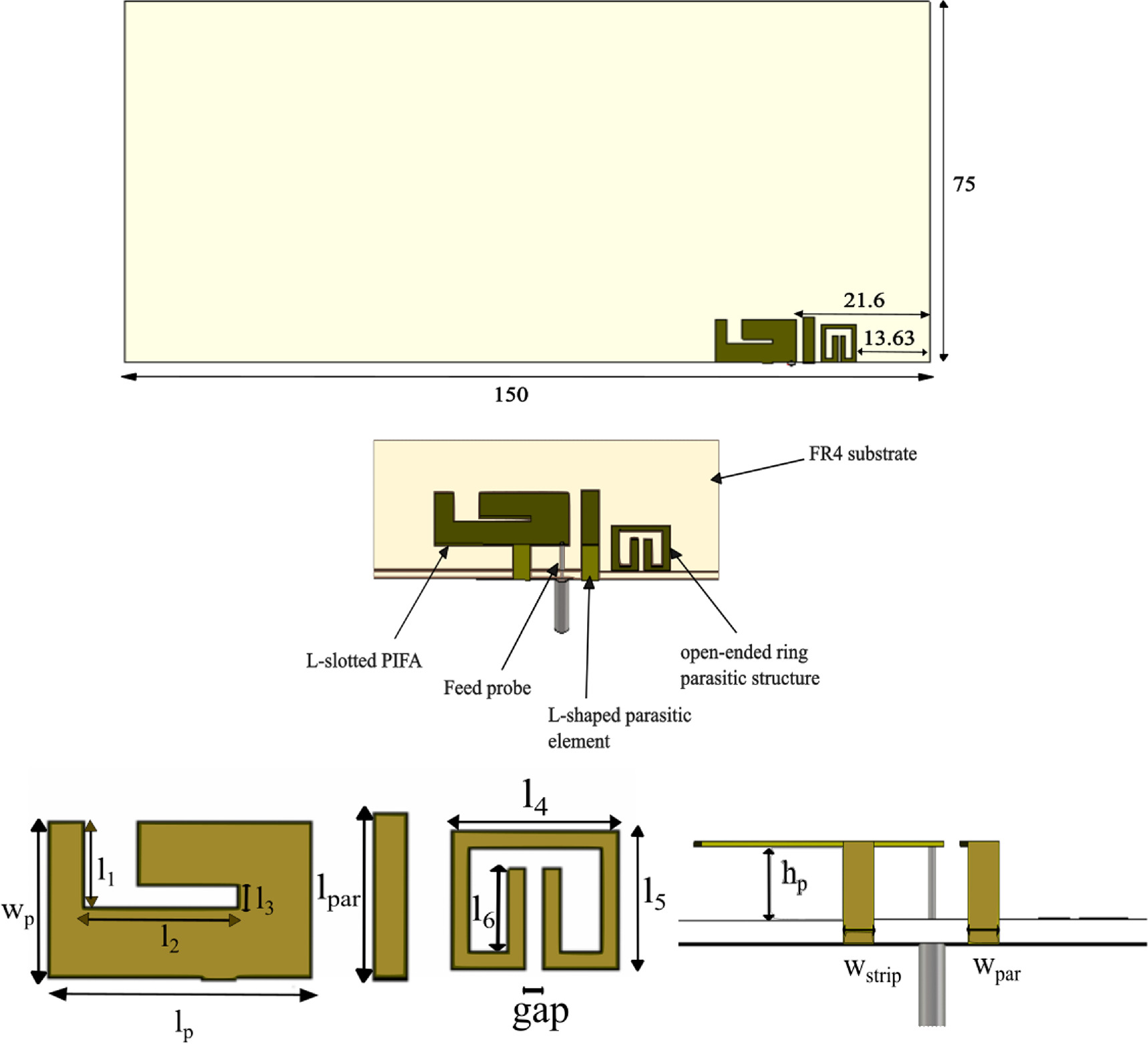
Figure 1. Layout of the proposed PIFA antenna element.
Download figure:
Standard image High-resolution image2.1. Antenna element evolution
The design procedure of the proposed antenna element is divided into four steps. Figure 2(a) visualizes the design steps of this antenna, while figure 2(b) depicts their S11 responses. First, the typical PIFA antenna is designed to operate at 3.6 GHz to cover the 3.4-3.8 GHz band (Ant. a). Here, the resonant frequency is determined by the length and width of the radiating plate, which can be approximated by the formula (1) [20]:

where c is the velocity of light, lp
and wp
are the length and width of the radiating plate, respectively,  r
is the relative dielectric constant of the substrate, and f0 is the operating frequency of the PIFA. From the result of the Ant. a, which is depicted in figure 2(b) (Ant. a), it can be clearly observed that the PIFA provides a resonance at 3.6 GHz with a −6 dB working bandwidth of 500 MHz (3.37-3.87 GHz), covering the 3.6 GHz 5G band. It is worth noting that the achieved −10 dB bandwidth is 280 MHz (3.47-3.75 GHz). Figure 3 depicts the current distribution of the Ant. a at 3.6 GHz. As shown, the current distributes on the surface of the strip and on some edges of the radiating plate of the PIFA.
r
is the relative dielectric constant of the substrate, and f0 is the operating frequency of the PIFA. From the result of the Ant. a, which is depicted in figure 2(b) (Ant. a), it can be clearly observed that the PIFA provides a resonance at 3.6 GHz with a −6 dB working bandwidth of 500 MHz (3.37-3.87 GHz), covering the 3.6 GHz 5G band. It is worth noting that the achieved −10 dB bandwidth is 280 MHz (3.47-3.75 GHz). Figure 3 depicts the current distribution of the Ant. a at 3.6 GHz. As shown, the current distributes on the surface of the strip and on some edges of the radiating plate of the PIFA.

Figure 2. (a) Antenna element design evolution and (b) its corresponding reflection coefficient.
Download figure:
Standard image High-resolution image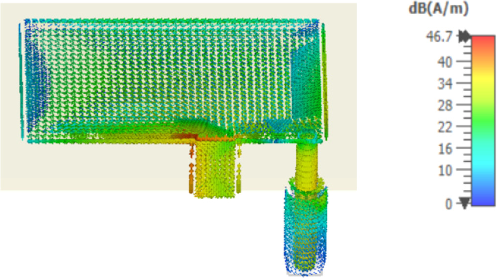
Figure 3. The current distribution of the Ant. a at 3.6 GHz.
Download figure:
Standard image High-resolution imageThen, the next step in our design consists of achieving dual-band characteristics to cover the entire WLAN band (5.15-5.85 GHz). For this, an L-shaped parasitic element and an L-shaped slot are added to the design (Ant. b and Ant. c). Here, instead of using the traditional method of etching slots on the radiating plate to excite the second resonance frequency of the PIFA and then adding a parasitic element to enhance the upper-band bandwidth, we propose a new method consisting of using a parasitic element to achieve dual-band operation and slots on the radiating plate to extend the upper-band bandwidth. The reason behind selecting the parasitic element to excite the first resonance frequency of the upper band rather than the slots is that etching slots on the radiating plate creates a narrow bandwidth that decreases with increasing the length of the slot, which influences the total bandwidth of the upper band. To prove that, the reflection coefficients S11 of the L-slotted PIFA with different values of L2 are displayed in figure 4(a). It can be clearly seen that the upper band bandwidth decreases when the length L2 increases: when L2 increases from 9 to 11 mm, the upper resonance frequency moves from 5.7 to 5.1 GHz, and the upper bandwidth shifts from 24 to 13 MHz. Further, figure 4(b) demonstrates that the upper bandwidth of the PIFA with only the L-shaped parasitic element is about twice as large as that of the L-slotted PIFA. It is worth mentioning that the size of the L-slot and the L-shape parasitic element are selected to have a resonance at 5.5 GHz. Finally, a comparison between the traditional and the proposed methods is depicted in figure 5 which shows that the proposed method has good impedance matching and a wider bandwidth.
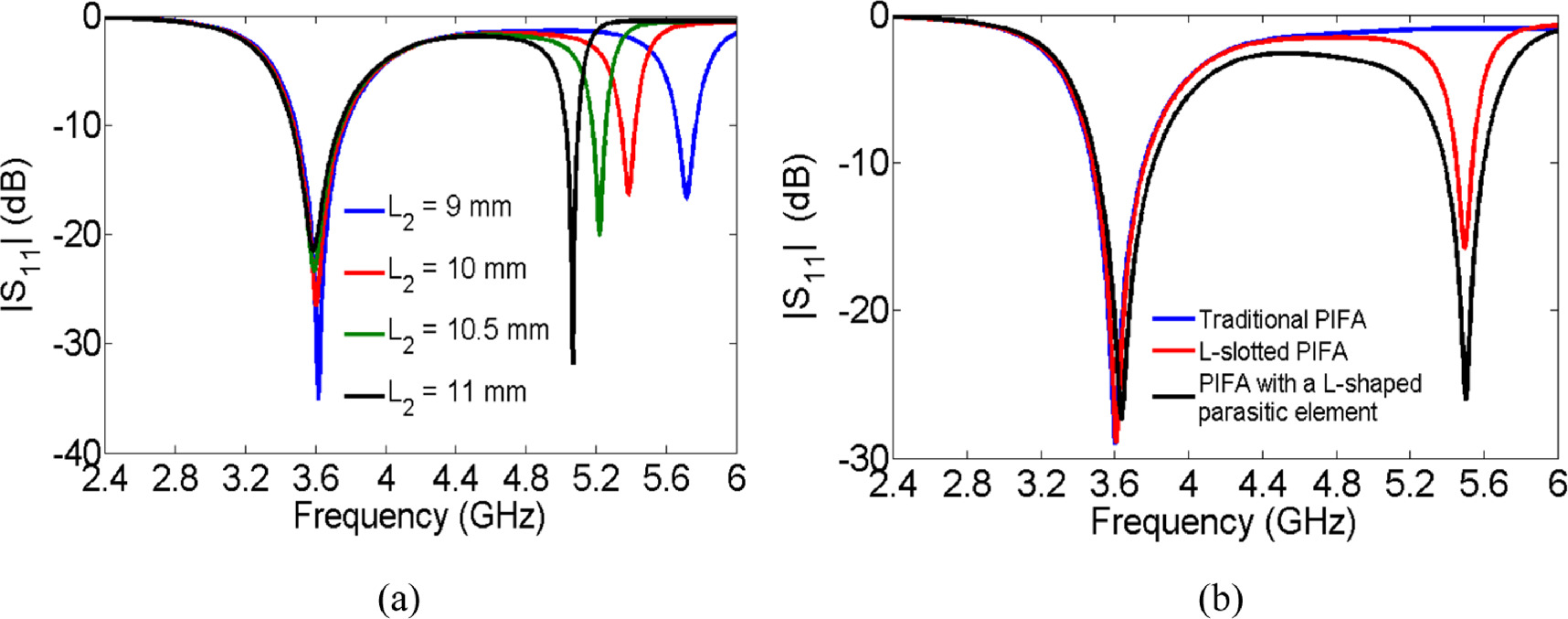
Figure 4. (a) The reflection coefficient of the L-slotted PIFA for different values of L2 and (b) A comparison between the L-slot PIFA and PIFA with only an L-shaped parasitic element at 5.5 GHz.
Download figure:
Standard image High-resolution image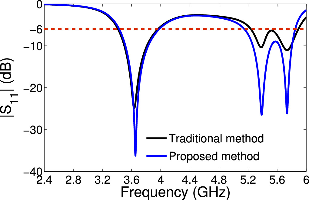
Figure 5. Comparison between the traditional method and the proposed method.
Download figure:
Standard image High-resolution imageThe reflection coefficients of Ant. b and Ant. c are displayed in figure 2(b). The −6 dB and −10 dB working bandwidths of the upper band of Ant. b are 350 MHz and 190 MHz, respectively. For Ant. c, the −6 dB working bandwidth of the upper band is 730 MHz, while for the −10 dB impedance condition, Ant. b has two bands in the upper band with a bandwidth of 240 MHz and 150 MHz, respectively.
To further explain the dual-band behavior of Ants. b and c, current distributions at the resonant frequencies of each antenna are shown in figure 6. For Ant. b and at 3.6 GHz, there is a nearly identical current distribution to the one of the PIFA without a L-shaped parasitic element (figure 3) with weak current flowing through the parasitic element. Thus, the first resonance is basically dependent on the PIFA and is slightly affected by the L-shaped parasitic element. At 5.37 GHz, the current is strongly distributed on the L-shape parasitic element and relatively weak at the edges of the PIFA next to the L-shaped parasitic element, which may be due to the coupling between them. This indicates that the L-shaped parasitic element is responsible for the second resonant frequency. The same behavior is observed for Ant. c at 3.6 and 5.37 GHz. At 5.75 GHz, we can observe that the L-shaped slot is responsible for creating another resonance in the upper band.
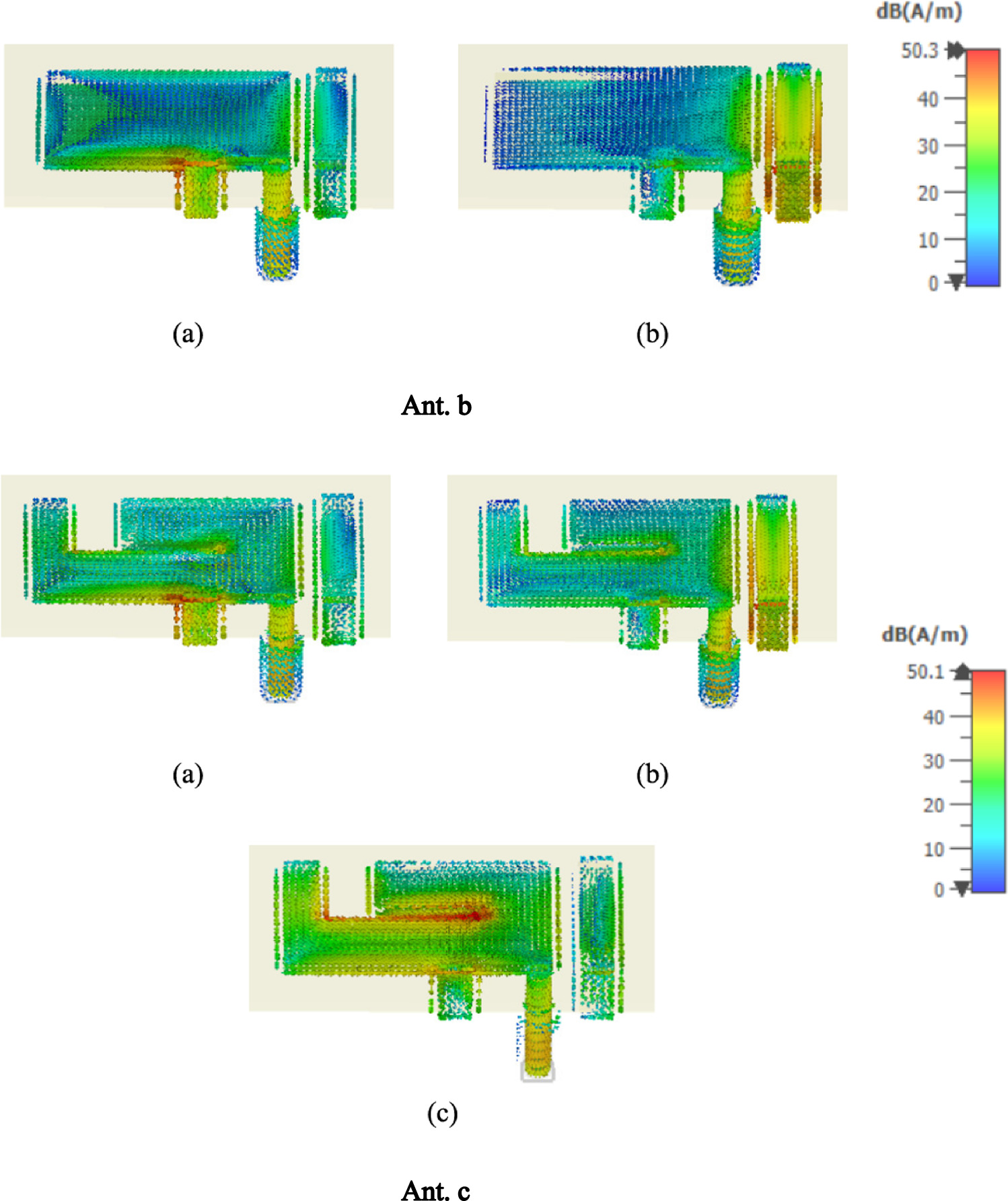
Figure 6. Current distributions of Ant. b and Ant. c : at (a) 3.6 GHz, (b) 5.37 GHz, and (c) 5.75 GHz.
Download figure:
Standard image High-resolution imageLastly, a rectangular open-ended ring parasitic structure is printed on the top layer of the substrate next to the L-shaped parasitic element in order to enhance the impedance matching of the antenna element at the upper band. This generates a new resonance at the center frequency of the WLAN band (5.5 GHz), as illustrated in figure 2 (Ant. d). The simulated reflection coefficient of this structure and the other previous configurations is shown in the same figure. Comparing the reflection coefficient of the final configuration of the antenna element to the previous starting configurations, it is evident that the bandwidth and impedance matching at the upper band are significantly improved.
Figure 7 shows the total efficiency of Ant. a to Ant. c. The total efficiency ranges from 75% to 97 % in the lower band for all antennas. However, in the upper band, it ranges from 19% to 97% for Ant. b, 69% to 97% for Ant. c, and 58% to 94 % for Ant. d. Due to using a printed rectangular open-ended ring parasitic structure, the total efficiency of the final configuration decreases from 91% to 64% compared with the configuration of the Ant. c. The reason for this decrease is that the printed rectangular open-ended ring parasitic structure introduces more losses at its resonant frequency (5.5 GHz).
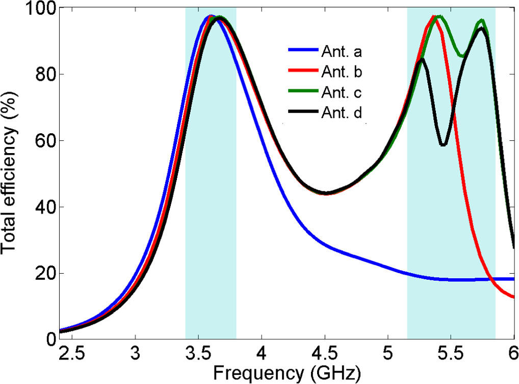
Figure 7. Simulated total efficiency of Ant. a, Ant. b, Ant. c and Ant. d.
Download figure:
Standard image High-resolution imageIn the final configuration of the antenna element, there is a slight change in the PIFA first resonance frequency (f0 = 3.6 GHz) when slots and parasitic elements are added to the antenna. Thus, additional optimization would be necessary. The final dimensions of the proposed antenna element are listed in table 1 and its reflection coefficient under CST and HFSS software is displayed in figure 8. The −6 dB working bandwidth in the lower and upper bands is 510 MHz (3.39-3.9 GHz) and 710 MHz (5.14-5.85 GHz). While for the -10 dB condition, the bandwidth in the lower and upper bands is 280 MHz (3.47-3.75 GHz) and 610 MHz (5.2-5.81 GHz) in both software, respectively.

Figure 8. Reflection coefficient of the proposed antenna element.
Download figure:
Standard image High-resolution imageTable 1. Dimensions of the proposed antenna element.
| Parameter | Value (mm) | Parameter | Value (mm) |
|---|---|---|---|
| lp | 14.92 | l3 | 0.9 |
| wp | 9 | l4 | 8 |
| l1 | 4.1 | l5 | 6.5 |
| l2 | 8.7 | l6 | 4.8 |
| wstrip = wpar | 1.9 | hp | 2.5 |
| gap | 0.7 | lpar | 9.45 |
Figure 9 illustrates the dual-band antenna element's current distributions at resonant frequencies, demonstrating the impact of all the previously discussed steps. Since the current is distributed on the strip's surface as well as on the PIFA antenna's radiation plate at 3.6 GHz, it is evident that the radiating plate of the PIFA is what causes the resonance frequency, whereas at 5.75 GHz, the current is distributed on the L-shaped slot. While the majority of the currents at 5.29 GHz are concentrated in the L-shaped parasitic element. At 5.5 GHz, most of the currents are dispersed around the rectangular open-ended ring.

Figure 9. Current distribution of the proposed PIFA antenna element: (a) at 3.6 GHz, (b) at 5.29 GHz, (c) at 5.5 GHz and (d) at 5.75 GHz.
Download figure:
Standard image High-resolution imageFigure 10 plots the radiation and total antenna efficiencies of the suggested antenna element. As can be observed, the CST radiation efficiency across the lower and upper bands varies roughly between 96%-98% and 61%-96%, while in HFSS it varies between 97%-99% and 60%-95%, respectively. Plus, the total efficiency in CST varies between 63.7%-96.7% in the lower band (55.5%-88.5% in HFSS) and between 58.6%-93.8% (55%-95 in HFSS) in the upper band.

Figure 10. (a) Radiation efficiency and (b) Antenna efficiency of the proposed antenna element.
Download figure:
Standard image High-resolution imageThe 2D radiation patterns of the antenna element in the xz and yz planes in CST and HFSS are plotted in figure 11. The maximum radiation pattern on the xz plane at 3.6 GHz, 5.29 GHz, and 5.5 GHz occurs at angles of 315°, 311°, 6°, while at 5.74 GHz, the maximum radiation is quite uniform. On the yz plane, the maximum radiation takes place at θ = 300° at 3.6 GHz, 5.29 GHz, and 5.5 GHz, while at 5.74 GHz, the maximum radiation pattern occurs at θ = 377°.

Figure 11. 2D radiation patterns of the proposed antenna element in the x-z and y-z planes.
Download figure:
Standard image High-resolution imageThe peak realized gain of the proposed antenna element is shown in figure 12. In CST, the minimum peak realized gain obtained in the lower band is 4.28 dB (3.6 dB in HFSS), while in the upper band it is 5.1 dB (5 dB in HFSS). However, the maximum peak realized gain obtained in the lower and upper bands in CST is 5.71 dB and 6.1 dB (5.97 dB and 7.18 dB in HFSS), respectively.

Figure 12. The peak realized gain of the proposed antenna element.
Download figure:
Standard image High-resolution image3. MIMO PIFA antenna performances
Figure 13 depicts the layout of the proposed dual-band eight-port MIMO PIFA antenna. The separation between adjacent antenna elements is 27.62 mm. In the following discussion, since Ant4, Ant5, Ant6, and Ant8 are considered to be similar to Ant3, Ant2, Ant1, and Ant7, respectively, Only the performances of Ant1, Ant2, Ant3, and Ant7 are provided.

Figure 13. Configuration of the proposed dual-band MIMO PIFA antenna.
Download figure:
Standard image High-resolution image3.1. S-parameters and efficiencies
The simulated curves of the S-parameters for Ant 1, 2, 3, and 7 are plotted in figure 14. The 6-dB bandwidths in the lower and upper bands of Ant1, Ant2, Ant3, and Ant 7 are 440 MHz (3.41-3.85 GHz) and 700 MHz (5.14-5.86 GHz), 490 MHz (3.42-3.91 GHz) and 710 MHz (5.15-5.86 GHz), 400 MHz (3.43-3.83 GHz) and 710 MHz (5.15-5.86 GHz), and 550 MHz (3.39-3.94 GHz) and 730 MHz (5.14-5.87 GHz) in CST. Whereas in HFSS are 440 MHz (3.41-3.85 GHz) and 720 MHz (5.13-5.85 GHz), 490 MHz (3.42-3.91 GHz) and 690 MHz (5.16-5.85 GHz), 380 MHz (3.44-3.82 GHz) and 700 MHz (5.15-5.85 GHz), and 540 MHz (3.39-3.93 GHz) and 710 MHz (5.14-5.85 GHz), respectively. The minimum isolation between adjacent antenna elements in CST is 12.2 dB in the lower band and 12 dB in HFSS, while in the upper band it is 16.4 dB in CST and 15.9 dB in HFSS. Plus, the maximum isolation in the lower band is between Ant3 and Ant7: 37.5 dB in CST and 33.7 dB in HFSS, while in the upper band it is between Ant1 and Ant6: 37.3 dB in CST and 30.6 dB in HFSS.
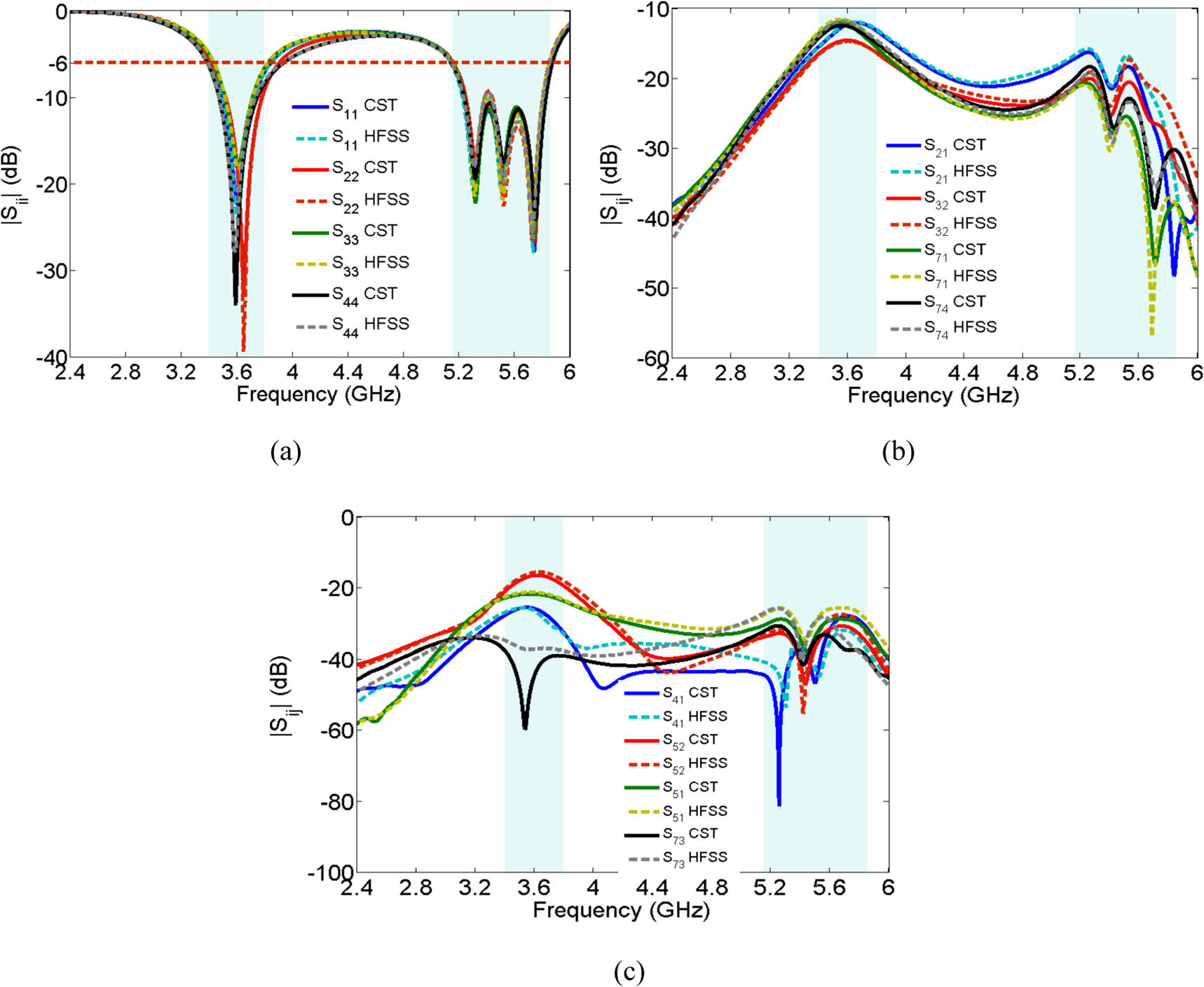
Figure 14. (a) Simulated reflection coefficients, (b) and (c) transmission coefficients of the proposed MIMO antenna.
Download figure:
Standard image High-resolution imageFurther, the surface currents of all eight antenna elements at 3.6 GHz, 5.29 GHz, 5.5 GHz, and 5.75 GHz are displayed in figure 15. At 3.6 GHz, there is strong current flowing on the ground plane around and between antenna elements, which increases the mutual coupling between antenna elements. However, at the other resonant frequencies, we can observe that the surface current is distributed only around antenna elements, which justifies the high isolation value in the upper band.
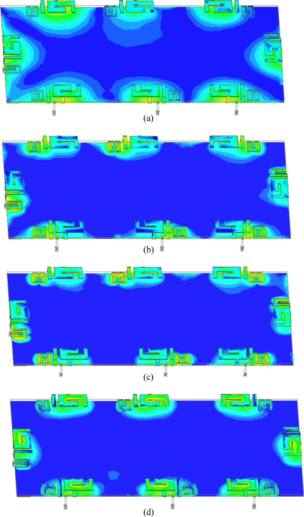
Figure 15. The surface currents of the proposed MIMO antenna: (a) at 3.6 GHz, (b) at 5.29 GHz (c) at 5.5 GHz and (d) 5.75 GHz.
Download figure:
Standard image High-resolution imageThe radiation and antenna efficiencies of Ant1 to Ant3 and Ant7 are plotted in figure 16. The radiation efficiency in the lower and upper bands ranges from 95% to 97% and 57.2% to 96.2% in CST, while in HFSS it ranges from 96.9% to 98.1% and 58.4% to 95.5%, respectively. In addition, the antenna efficiency in CST of all antennas is between 61.1% and 91.2% in the lower band (65.7% and 97.4% in HFSS), while in the upper band it ranges from 53% and 95.4% (52.9% and 95.1% in HFSS).

Figure 16. (a) Radiation efficiency and (b) antenna efficiency of the proposedMIMO PIFA antenna.
Download figure:
Standard image High-resolution image3.2. Radiation patterns and the peak realized gains
The 2D radiation patterns in the xz and yz planes at the center frequency of the 3.6 GHz 5G band and 5.5 GHz WLAN band for Ant1 to Ant3 and Ant 7 on both software are depicted in figures 17 and 18. We can see that each antenna has a different radiation pattern, which lowers the ECC.
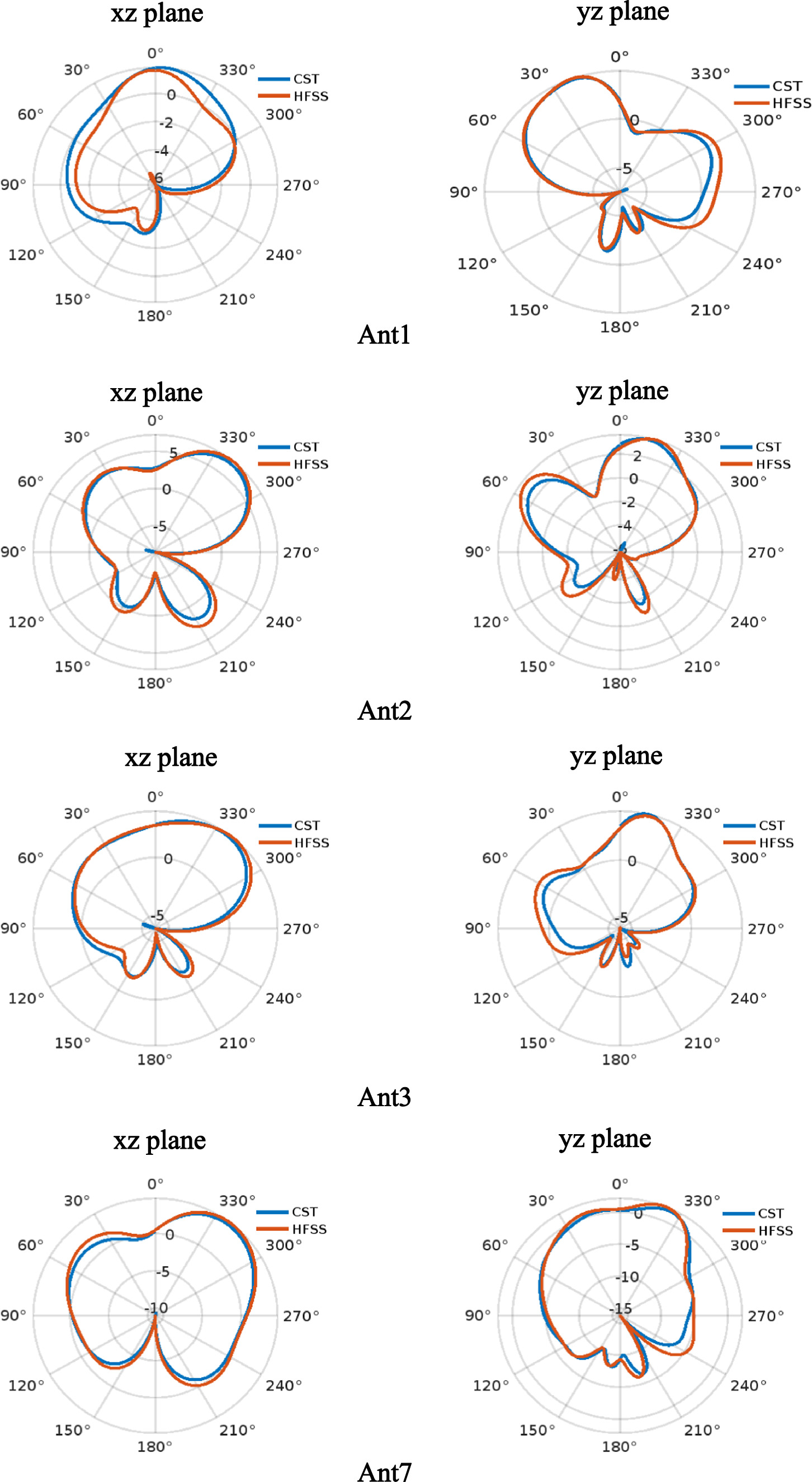
Figure 17. Radiation patterns of Ant1, Ant2, Ant3 and Ant7 at 3.6 GHz.
Download figure:
Standard image High-resolution image
Figure 18. Radiation patterns of Ant1, Ant2, Ant3 and Ant7 at 5.5 GHz.
Download figure:
Standard image High-resolution imagePeak realized gains of Ant1 to 3 and Ant7 are plotted in figure 19. The minimum realized gain for Ant1 to 3 and Ant7 in the lower band is 4.16 dB, 4.6 dB, 4.87 dB, and 4.37 dB in CST, while in HFSS it is 4.33 dB, 4.66 dB, 4.86 dB, and 4.37 dB. Whereas in the upper band it is 3.7 dB, 4 dB, 4.3 dB and 4.2 dB in CST, and 4.7 dB, 4.5 dB, 5.4 dB and 4.5 dB in HFSS, respectively. The maximum realized gain in the lower band is 5.5 dB, 7.12 dB, 6.15 dB, and 5.1 dB for Ant1, Ant2, Ant3, and Ant7 in CST, and it is 5.51 dB, 7.21 dB, 5.68 dB, and 5.6 dB in HFSS. While in the upper band it is 6.7 dB, 5.9 dB, 5.8 dB and 6.3 dB in CST, and 6.8 dB, 6.3 dB, 5.8 dB and 6.4 dB in HFSS, respectively.
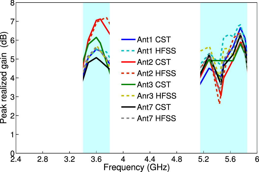
Figure 19. Peak realized gain of Ant1, Ant2, Ant3 and Ant7.
Download figure:
Standard image High-resolution image3.3. Envelope correlation coefficient
The envelope correlation coefficient (ECC) is an important parameter to evaluate diversity performance. It measures how well the received signals from the transmitting antennas are independent. The ECC of Ant1 to Ant3 and Ant7 is calculated using the formula in [21] using the radiation pattern approach and are displayed in figure 20. As shown, the ECC in CST is below 0.05 and 0.03 in the lower and upper bands, while in HFSS it is below 0.18 and 0.04, respectively, satisfying the ECC requirements for MIMO antenna systems, which state that they must be smaller than 0.5.
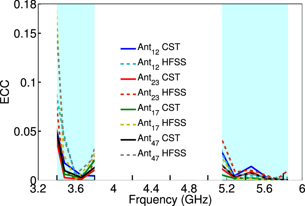
Figure 20. ECC between adjacent antenna elements.
Download figure:
Standard image High-resolution image3.4. Diversity gain
Diversity combats multipath fading by transmitting multiple copies of the same signals to the receiver via different channel paths. Diversity gain measures the improvement in the communication system due to the use of diversity and can be calculated using the following formula (2):

From figure 21, it can be seen that the value of DG in the lower band is <9.9 dB in CST, and in HFSS it is <9.5 dB. Whereas in the upper band, it is <9.9 dB in both software.
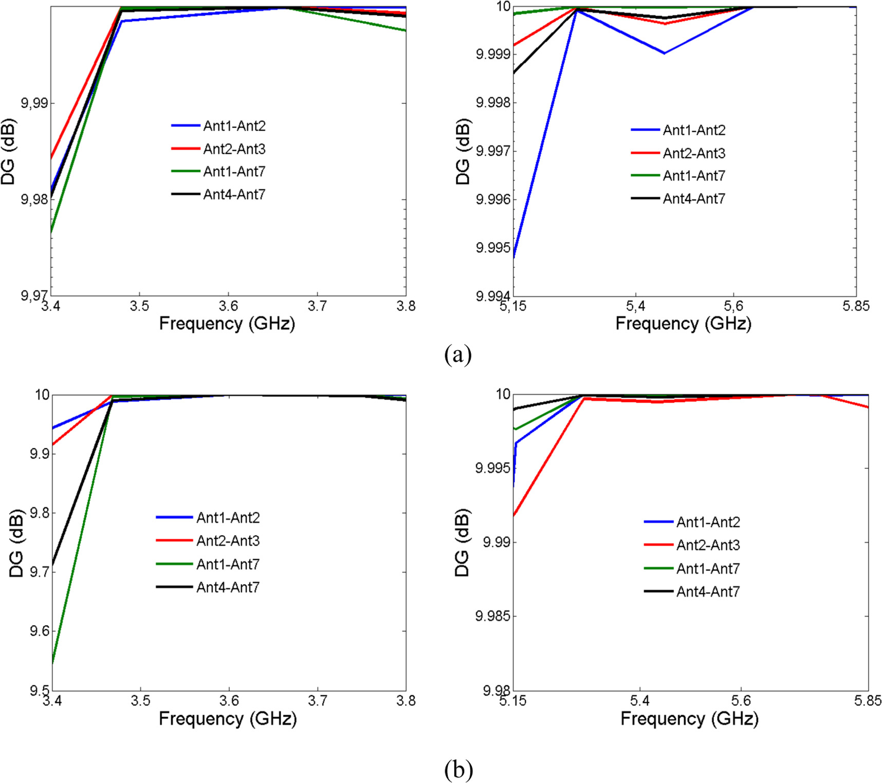
Figure 21. Diversity gain of adjacent antenna elements: (a) in CST and (b) in HFSS.
Download figure:
Standard image High-resolution image3.5. Mean effective gain
The mean effective gain (MEG) of an antenna is defined as the ratio of the received power in a fading environment to the power that would be received by an isotropic antenna and can be calculated using the formula below:

iwhere M is the total number of antenna elements. In order to achieve optimal power balance and diversity performance, the absolute value of the ratio ∣MEGi ∣/∣MEGj ∣ should be below 3, where i and j are the number of antenna elements.
The calculated MEG of Ant1 to Ant3 and Ant7 is presented in table 2. The MEGs of all antennas are below -4 dBi, and it can be easily seen that the ratio of MEGs is below 3.
Table 2. Calculated MEGs for Ant1, Ant2, Ant3 and Ant7 at the resonant frequencies in CST.
| Frequency (GHz) | MEG Ant1 (dBi) | MEG Ant2 (dBi) | MEG Ant3 (dBi) | MEG Ant7 (dBi) |
|---|---|---|---|---|
| 3.6 | −3.72 | −3.76 | −3.69 | −3.56 |
| 5.29 | −3.2 | −3.32 | −3.41 | −3.16 |
| 5.5 | −3.17 | −3.21 | −3.27 | −3.28 |
| 5.75 | −3.05 | −3.05 | −3.06 | −3.03 |
3.6. Multiplexing efficiency
The multiplexing efficiency (ME) ηMux is the ratio of the signal-to-noise ratio of an ideal MIMO antenna to the signal-to-noise ratio of a given MIMO antenna and is expressed as [22]:

where ρc is the complex correlation coefficient between the antenna elements (∣ρc ∣2 ≈ ECC). ηi and ηj are the total efficiency of the ith and jth antenna elements. Figure 22 plots the MEs of Ant1 to Ant3 and Ant7. It can be observed that the value of the ME of all antennas is above -3 dB.

Figure 22. The ME between adjacent antenna elements.
Download figure:
Standard image High-resolution image3.7. Total active reflection coefficient and capacity channel loss
The ratio of the square root of the total reflected power to the square root of the total incident power is known as the total active reflection coefficient (TARC) and can be computed using the following expression [23]:

The channel's capacity loss resulting from the MIMO links' correlation is called channel capacity loss (CCL) and is given by [24]:

where ak is the correlation matrix and its element can be calculated using the expressions below:


Both TARC and CCL are displayed in figures 23 and 24. From this figure, we can observe that the bandwidth of the adjacent antennas in the lower band is reduced and the CCL is more than 0.4 dB due to the coupling between them compared with the upper band, and that because in the upper band the current distribution is mainly concentrated in the vicinity of the L-shaped parasitic element, which increases the isolation.

Figure 23. (a) The TARC of the MIMO antenna: (a) in CST and (b) in HFSS.
Download figure:
Standard image High-resolution image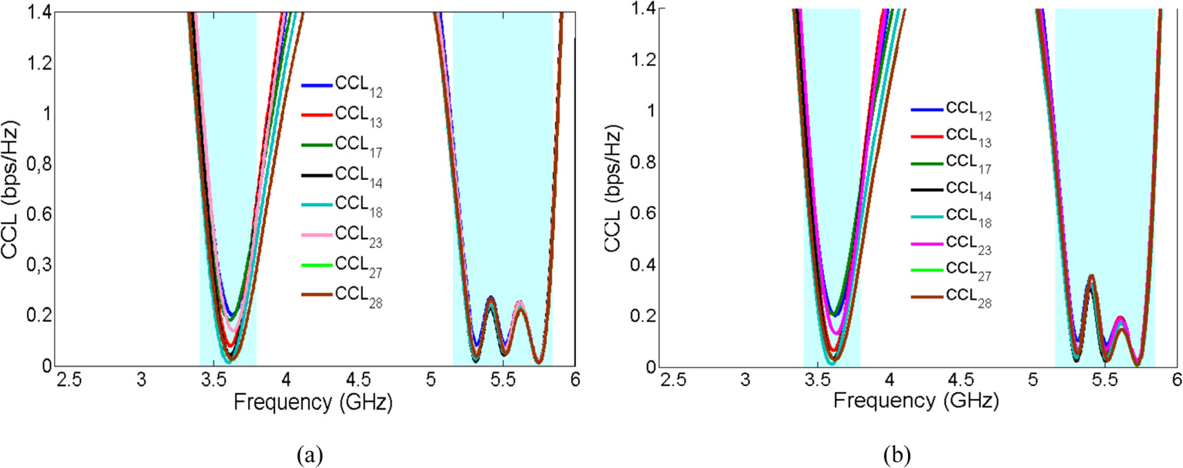
Figure 24. (a) The CCL of the MIMO antenna: (a) in CST and (b) in HFSS.
Download figure:
Standard image High-resolution image
4. Discussion
Table 3 gives a comparison between the stated MIMO antenna and another reported MIMO PIFA antennas for 5G mobile terminals. The height of the suggested MIMO PIFA antenna is the lowest at just 2.5 mm compared with other MIMO PIFA antennas. Due to using a new technique to enhance the upper-band bandwidth with a printed rectangular open-ended ring prasitic structure, the proposed MIMO antenna can cover the WLAN band without increasing the height of the PIFA or using DGS structures. Further, all of the MIMO PIFA antennas shown in the same table have a number of ports less than 8, with the exception of the antennas in [16].
Table 3. Comparison between our MIMO antenna and the referenced MIMO PIFA antennas.
| References | Nbre of ports | Height of PIFA | Frequency band (GHz) | Minimum isolation (dB) | ECC |
|---|---|---|---|---|---|
| [15] | 4 | 3 | 2.7-3.6 (-10 dB) | 25 | <0.009 |
| [14] | 2 | 7.7 | 2.5-2.7/3.4-3.8 | — | — |
| [16] | 8 | 3.5 | 2.4-3.8 (-10 dB) | 13 | <0.03 |
| [17] | 2 | 3.5 | 2-3.6 (-10 dB) | 19 | 0.21 |
| [18] | 2 |

|

| >10 |

|
| This work | 8 | 2.5 | 3.43-3.8/5.15-5.85 (-6 dB) | >12.1/>16 | <0.05 |
In addition to that, the proposed MIMO PIFA antenna is also compared with other MIMO antennas, and the comparison is summarized in table 4. The proposed MIMO antenna has better isolation between neighboring antenna elements than references [25–30], in addition to covering the 3.6 GHz 5G band and 5.5 GHz WLAN band. Good performance that satisfies 5G mobile communications requirements in terms of ECC, DG, MEG, and ME is obtained.
Table 4. Comparison between our MIMO antenna and the referenced MIMO antennas.
| References | Nbre of ports | Antenna type | Frequency band (GHz) | Efficiency | Minimum Isolation (dB) | ECC |
|---|---|---|---|---|---|---|
| [31] | 8 | IFA antenna | 3.4-3.8 (-6 dB) | >40 | >12 .1 | <0.23 |
| [26] | 8 | slot antenna | 3.3-6 (-6 dB) | 50-61 | >12 .1 | <0.2 |
| [25] | 8 | H-shaped antenna | 3.1-3.9/5.5-6.3 (-6 dB) | 70-80 | >12/>12 | <0.035 |
| [32] | 8 | Split-Ring Resonator | 3.3-3.5 (-10 dB) | 40-82 | 12 | <0.12 |
| [33] | 8 | Planar shared— radiator antenna | 3.3-4.2 (-6 dB) | 63.1-85.1 | >10.5 | <0.2 |
| [28] | 8 | Slot antenna | 3.4-3.6 5.15-5.925 (10 dB) | 51-59/62-80 | >11.2 | <0.08 |
| [34] | 8 | Slot and monopole antenna | 3.4-3.6 (10 dB)5.15-5.925 (6 dB) | 5056/5365 | >12 | <0.1/<0.04 |
| [29] | 8 | Slot antenna | 3.4-3.6 4.8-5 (6 dB) | >40/>70 | >12 | <0.15/<0.06 |
| [35] | 8 | Symmetric dipole antenna | 3.45-3.55 (-6 dB) | 48-67 | >16 | 0.08 |
| [30] | 8 | F-shaped radiator | 3.4-3.6 4.8-6 (-6 dB) | 52-88 | >15 | <0.16 |
| [36] | 8 | monopole | 3.3-4.2 4.8-5 (-6 dB) | 53.8-76.5/ 62.6-79.1 | >11.5/>15 | <0.1/<0.12 |
| [37] | 8 | loop antenna | 3.2-4 (- 10 dB) | 50-75 | 11 | <0.005 |
| This work | 8 | PIFA | 3.43-3.8/5.15-5.85 (-6 dB) | 61.1-91.2/ 53-95.4 | >12.1/>16 | <0.05 |
5. Conclusion
In this study, an ultra-thick 8-port dual-band MIMO PIFA to meet the requirements of 5G mobile terminals in the sub-6 GHz spectrum is presented. First, a dual-band PIFA antenna with a height of 2.5 mm is designed, and a new method is proposed to achieve dual-band operation with wideband bandwidth by using a L-shaped parasitic element and an etching slot on the radiating plate of the PIFA. Then, for the first time, a 2D rectangilar open-ended ring parasitic structure with PIFA was used to improve the impedance matching in the upper-band bandwidth. Finally, a configuration composed of 8-port PIFA elements for mobile terminals is proposed that could offer us good MIMO performances in terms of isolation (more than 12 dB in the lower band and 16 dB in the upper band), efficiency (61.1-91.2/53-95.4%), ECC (lower than 0.05), DG (9.9 dB), and MEG (the ratio of antenna MEGs is below 3).
Data availability statement
All data that support the findings of this study are included within the article The data that support the findings of this study are available upon reasonable request from the authors.