

Abstract
A damping fuzzy proportional-integral-derivative (PID) control method for electronically controlled air suspension shock absorbers was proposed to reduce the RMS values of the body vibration acceleration and improve vehicle ride comfort. Depending on the operating mode of the electronically controlled air suspension shock absorber, a mechanical model of the air suspension shock absorber was established. A fuzzy PID control technology for damping control of the shock absorber is designed by combining a PID control algorithm with the fuzzy control concept. The adaptive expansion factor of the cybernetics domain for the fuzzy PID controller is calculated by considering nonlinear characteristics and time delay to improve the controller's adaptability. Then, the control parameters are adjusted based on the control deviation and deviation rate parameters. The nonlinear detection platform produced by an enterprise is selected to build an experimental environment for analysis. Simulation results reveal that when the vehicle speed is 30 km h−1, the RMS values of the body vibration acceleration upon applying the proposed method is approximately 0.02 and 0.05 km h−2, respectively, on Class B and C road surfaces. Furthermore, the RMS values of the body vibration acceleration using the proposed method has little fluctuation; when the vehicle speed is 60 km h−1, the RMS values of the body vibration acceleration is 0.022 and 0.028 km h−2, respectively, on Class B and C road surfaces, indicating that the proposed method can effectively reduce the RMS values of the body vibration acceleration and improve rider comfort.
Export citation and abstract BibTeX RIS
1. Introduction
Vehicles are easily affected by road inequality factors, resulting in poor vehicle stability while driving. PID control, which is simple and convenient, is the main control method in industrial production. The control parameters are adjusted based on the value of each structural parameter change, but the parameter tuning of PID control is always difficult. When the control target has high time variability and nonlinearity, a set of PID parameters cannot meet practical needs. However, existing damping-control methods for electronically controlled air suspension shock absorbers cannot meet the increasingly stringent requirements of damping absorber regulation.
Currently, most passenger cars and commercial vehicles in China are equipped with air suspension, ensuring the stability of automobile operation by controlling the airbag pressure of the air springs [1]. Electronically controlled air suspension for vehicle stability control can be achieved through shock absorber damping control [2]. Ding et al [3] proposed the LQR control method of vehicle active suspension based on the adaptive multi-population genetic algorithm. An adaptive genetic algorithm was used to adjust the parameters adaptively to improve the convergence rate. A multigroup genetic algorithm was used for collaborative optimisation among populations to improve the convergence of controller parameters. This method effectively reduces the amplitude of vertical suspension but does not account for the nonlinear characteristics of the control, resulting in poor usability.
Gao et al [4] proposed an online control method of suspension vibration energy recovery for new energy vehicles. The damping of a high-frequency DC–DC converter is adjusted by adopting an electromagnetic damper comprising a DC motor and ball screw mechanism, and the output voltage is adjusted according to the input voltage. On this basis, the target electromagnetic torque of the damper is calculated, and the armature current required to meet the reference torque is obtained. Simultaneously, through the continuous acquisition of the actual armature current, an actual current input PI controller is used for PI closed-loop adjustment to achieve the control of the pulse-width modulation (PWM) signal. The PWM controller is used to adjust the 1-kHz DC–DC converter to track and restore the target torque. The damping coefficient adjustment and control scheme is effective. However, this control method does not consider the delay factor, so it is not ideal for improving the vehicle ride.
Zhang et al [5] adopted the concept of velocity-driven damping, selected the most effective damping coefficient for damping control of the shock absorber, verified the application effect of ADD control strategy, and established an ideal control model. However, the controller in this method has low adaptability, leading to a poor acceleration suppression effect.
This paper presents a fuzzy PID control method for electrically controlled air suspension shock absorber damping in automobiles to improve vehicle ride comfort. Based on the working principle of the shock absorber, a mechanical model of the air suspension shock absorber was constructed. The fuzzy PID control technology was designed based on the PID control algorithm and fuzzy control theory. Nonlinear characteristics and time-delay factors were used to calculate the domain adaptive expansion factor. In addition, the particle swarm optimisation algorithm was introduced to adjust the damping-control parameters. A fuzzy PID control method for automotive electrically controlled air suspension shock absorber damping is designed.
2. Damping fuzzy PID control method design
2.1. Building the mechanical model
The type of damper in this paper is ER damper. Given the operation mode of the electronically controlled air suspension of the automobile, the overall mechanical shock-absorber model was constructed according to the one-fourth body model, as illustrated in figure 1.
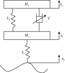
Figure 1. Overall mechanical model of the shock absorber.
Download figure:
Standard image High-resolution imageIn figure 1,  represents the unsprung mass (i.e., the wheel mass),
  denotes the sprung mass (i.e., body mass),
  is the tyre stiffness,
  indicates the electronically controlled air suspension stiffness,
  denotes the controllable damping coefficient of the shock absorber,
  represents the vertical wheel displacement,
  is the vertical displacement of the vehicle body, and
  denotes the road excitation coefficient.
The purpose of controlling the damping of the electronically controlled air suspension shock absorber can be controlled by changing the control current of the shock absorber and adjusting the damping coefficient [6, 7]. A larger damping coefficient results in faster energy dissipation and better suspension performance.
When designing a damping fuzzy PID control method for the shock absorber, the mechanical model of the shock absorber in figure 1 is considered, and Newton's second law is used to generate the kinetic equation of the shock absorber:

where  idenotes the speed of piston movemen, and
  indicates the moment of momentum. As the operating mode of the electronically controlled air suspension shock absorber is characterised by mixing, the damping force calculation formula can be expressed as follows:

where  represents the damping force of the shock absorber,
  denotes the zero-field viscosity,
  indicates the magnetic coil current,
  is the liquid magnetorheological constant,
  represents the magnetic induction intensity, and
  denote the piston structure constant. The subsequent damping-control technology was designed based on the mechanical model and damping force calculation formula of the air suspension shock absorber.
2.2. Designing fuzzy PID controller
Based on the PID control theory, the direct digital control mode controls the error proportion, error integral, and error differential parameters to achieve satisfactory electronically controlled air suspension shock absorber damping control. A larger damping coefficient results in better controller performance and faster response. According to the system error and error change rate, the controller parameters are obtained. The design for the fuzzy PID controller includes three processes: fuzzification, fuzzy inference rule and unfuzzification. Fuzzy processing involves expressing the input and output of the system via a language rule. A complex system can be expressed using a simple language rule. Considering the complex operating environment of an automobile's electronically controlled air-suspension shock absorber, a simple PID controller has difficulty achieving a satisfactory control effect [8]. In this study, the PID control algorithm serves as the core, combined with the fuzzy control theory, to design fuzzy PID control technology with the error value and error rate as the input vector. The application of fuzzy PID control technology primarily relies on proportional, integral, and differential control parameters to achieve self-tune shock-absorber damping [9, 10]. The proposed fuzzy PID control structure is depicted in figure 2.
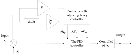
Figure 2. Fuzzy PID control.
Download figure:
Standard image High-resolution imageThe input range of the fuzzy controller is [−3,−1], and the output range is [−0.3,−0.1]. The output is the control force of the controller, and the maximum force required to overcome the vibration increases with the increase of the output range. Set the basic domain of the control quantity as ![$\left[-Q,Q\right]$](https://content.cld.iop.org/journals/2631-8695/4/4/045020/revision2/erxaca13aieqn17.gif) and the fuzzy subset domain of the control quantity as
and the fuzzy subset domain of the control quantity as ![$\left[-q,-q+1,0,q-1,q\right],$](https://content.cld.iop.org/journals/2631-8695/4/4/045020/revision2/erxaca13aieqn18.gif) then the scale factor of the output control quantity can be expressed as:
then the scale factor of the output control quantity can be expressed as:

The mechanical parameters of the air suspension shock absorber are regarded as the input parameters of the fuzzy PID controller [11, 12]. The incremental values of fuzzy PID control parameters are obtained using fuzzy rules, and the three existing fuzzy damping-control parameters are adjusted in real time to ensure the optimal dynamic control effect of shock-absorber damping. The specific fuzzy PID control adjustment formula can be expressed as follows:

where  represents the scale factor,
  indicates the integral factor,
  denotes the differential factor,
  is the proportional control parameter,
  denotes the integral control parameter,
  is the differential control parameter. Moreover,
 represent the initial value of the three control parameters, and
 denote the fuzzy control increment. The boundary values of
 and
and  are determined according to the input and output ranges of the fuzzy controller. For the input and output variables of the fuzzy PID controller, several fuzzy subsets, such as negative large, negative medium, and negative small, are established. The input vector domain and output vector domains are established and divided into seven fuzzy subsets: NB, NM, NS, ZE, PS, PM and PB. Rules table for Fuzzy is shown in table 1.
Table 1. Fuzzy rule-table.
| EC | |||||||
|---|---|---|---|---|---|---|---|
| E | NB | NM | NS | ZE | PS | PM | PB |
| NB | PB | PB | PB | PB | PB | PB | PB |
| NM | PB | PB | PB | PB | PM | PM | PS |
| NS | PM | PM | PM | PS | PS | ZE | ZE |
| ZE | PM | PS | PS | ZE | NS | NM | NM |
| PS | ZE | NS | NS | NM | NM | NM | NB |
| PM | NS | NS | NM | NM | NM | NB | NB |
| PB | NM | NM | NB | NB | NB | NB | NB |
In the damping fuzzy PID control of an automobile's electronically controlled air suspension damper, the initial theory domain boundary  of the error value and the initial theory domain boundary
  of the error change rate are the input vector for fuzzy PID control. The theory domain of the fuzzy set is defined by its variation. There are five units in the two input fuzzy sets:

The corresponding fuzzy subset of the two variables is the same (i.e., NM, NS, ZE, PS and PM).
As a basic component of shock-absorber damping control, fuzzy PID control rules [13, 14] are designed based on the connection between input and output variables and the actual control requirements of a shock absorber during automobile operation. The input and output are converted into language control variables using the triangle membership function, and the corresponding membership relation is given to create fuzzy reasoning rules. A fuzzy logic controller is composed according to if-then rules in the following format:

where  indicates the rule number, & denotes the fuzzy AND operation,
  is the previous language form of the rule, and
  represents the mark of the rule result.
The last step of the fuzzy PID control technology design is to defuzzify the output control variables. Based on the actual control object, the centre of gravity method is adopted to obtain an accurate control quantity as follows:

where  denotes the fuzzy output elements,
  is the number of
  and
and  represents the membership degree of
Fuzzy output elements with different membership degrees can be integrated using the centre of gravity method into a precise control quantity  which must be multiplied by the scale factor
  of the control system to obtain the actual control quantity.
2.3. Calculating the adaptive scaling factor of the domain
When applying fuzzy PID control technology, the values of control parameters and basic cybernetics directly affect the results of the fuzzy PID control. If the basic theory field is too large or too small, fuzzy rules are idle, or the output adjustment quantity error is large. Fuzzy logic is used to control the characteristic fusion data of the electrically controlled air-suspension damper and enhance the control effect of the fuzzy PID controller. According to the damping value, the suspension control unit can be adjusted effectively, and the vehicle operating stability can be improved. In this paper, the adaptive expansion factor of the theory domain is calculated to strengthen the fuzzy PID control ability for the basic cybernetic domain [15, 16] to ensure the adaptive ability of the fuzzy PID controller. The surface diagram of fuzzy logic is presented in figure 3.

Figure 3. Surface diagram of fuzzy logic.
Download figure:
Standard image High-resolution imageThis paper employs fuzzy PID control technology, electronically controlled air-suspension shock-absorber damping control, idea integration, and the variable region near the fuzzy PID control module. We set up a field adjustment module according to the feedback PID control error, error change rate, gain theory domain (to adjust the input vector), and output region (to adjust the proportion coefficient) [17, 18]. Under the premise of not affecting the basic theory domain, the scope of the cybernetic domain is adjusted adaptively to ensure that the fuzzy PID control technology can achieve satisfactory damping control of the shock absorber in various environments.
During the calculation, the error information and error change rate are used to change fuzzy PID control parameters dynamically. The specific online adjustment expression of control parameters is as follows:

where  represents the control time,
  denotes the error value, and
  is the damping-control parameter of the shock absorber. By introducing an expansion factor, online adjustment was compared with the fuzzy PID cybernetic domain to obtain the variable theory domain that meets the calculation requirements. The basic principle of the variable theory domain is illustrated in figure 4.

Figure 4. Fundamental principle of variable domains.
Download figure:
Standard image High-resolution imageAccording to the basic principle of the variable theory domain in figure 4, when applying fuzzy PID control technology to adjust shock-absorber damping, nonlinear control characteristics and delay factors must be considered and perfect fuzzy control rules based on the expansion factor must be built. In this study, the function model is proposed to design the VLJFP (Variable Universe Junction Factor Particle) calculation method. The scaling factor was designed through certain special functions [19, 20]. Therefore, the proportional exponential function model was adopted to establish the scaling factor calculation formula as follows:

where  and
and  represent expansion factors,
  denotes the error rate of change,
  is a small positive number, and

 represent the expansion factor design parameters.
According to the scale exponential function model, the selection of constants in the calculation process is often artificial and does not have a clear physical meaning. This problem was investigated and analysed, and the error value and error change rate were used to adjust the design parameters of the expansion factor in real time:

where  represents a sufficiently small positive number. The value is 1 when the result of Formula (9) is greater than 1. Moreover, the design parameters of the four stretching factors in Formula (8) were kept consistent to ensure the synchronisation of input and output variables. Through a reasonable value of the actual parameters of the expansion factor, the calculation formula of the expansion factor improved, and the adaptive change of the fuzzy PID cybernetic domain was realised.
2.4. Adjusting damping-control parameters of the shock absorber
The influence of various parameter values on the output characteristics of the shock absorber was analysed based on the three control parameters in the fuzzy PID control technology. Combined with the control debugging results, the variation trend of the damping-control deviation value and deviation rate data was summarised, and the self-tuning principle of control parameters was obtained.
When the damping-control error of the shock absorber is too large, it indicates that it is in the control response stage. The three control parameters must be analysed individually to confirm that the proportional coefficient is large when the differential and integral parameters are not in the saturation state to accelerate the control response and prevent an increase in the control error [21, 22]. In this case, the control parameter settings must exclude the role of differential parameters in the damping-control process. When the shock-absorber damping-control feedback is given, the control error value and error change rate are medium. To reduce the overshoot of the control method, the value of proportional control parameters must be as small as possible, whereas the value of differential control parameters and integral control parameters remain medium [23].
When the feedback result of the deviation value is large, the control parameters are changed using the forced setting method, and three PID control parameters are set in descending order from large to small to strengthen the steady-state performance of the damping control of the electronically controlled air-suspension shock absorber. When the shock-absorber damping-control feedback error is small, the control parameters can be adjusted through a) the normal setting mode, b) three control parameters in the differential value maximum, and c) (from large to small) the proportion parameter value, integral value, change in the error change trend, and the oscillation-frequency damping-control process.
When the error change rate is high, the common parameter setting strategy can be used to adjust the fuzzy PID control parameters; set large integral parameters, medium proportion parameters, and small differential parameters; and strengthen the dynamic performance of the controller damping adjustment. When the error change rate is low, the proportional and differential parameter values must be promoted synchronously to avoid substantial changes in the damping-control parameter value of the shock absorber and strengthen the anti-interference ability of the fuzzy PID control method. In contrast, the integral parameter value is usually set to medium.
Furthermore, the lag of damping control of the shock absorber is the main factor causing the poor dynamic characteristics of the damping-control effect [24]. The PID fuzzy control method was designed in this paper to solve the problem of control overshoot and continuous oscillation, with the closed-loop stability as the core of the requirements of the shock-absorber damping-control parameters with a reasonable parameter setting time, the highest frequency of sampling analysis, comprehensive acquisition of different PID control parameters, and control error and control error rate change.
The particle swarm optimisation algorithm was used to design an intelligent control parameter optimisation algorithm similar to a genetic algorithm by referring to the predation behaviour of birds when adjusting control parameters according to this setting mode to improve the speed of parameter setting and ensure the rationality of damping-control parameters. The flowchart of particle swarm optimization (PSO) algorithm is shown in figure 5.
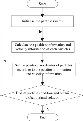
Figure 5. Flowchart of PSO algorithm.
Download figure:
Standard image High-resolution imageAll parameters in fuzzy PID control technology were initialised, and a random particle swarm was established. Each particle in the swarm represents a setting result for the damping-control parameter, and the corresponding position information and velocity information were set for each particle. Finally, the particle position coordinates were set according to the fitness value of the objective function value. In the iterative calculation process of the particle swarm, the conditions of particles were constantly updated according to the results of the maximum and minimum calculations, obtaining the optimal solution for individual particles. Moreover, the global optimal solution was obtained for the entire particle population.
Based on the operation requirements for the electronically controlled air-suspension shock absorber, the PID control parameters were set as objective optimisation variables, and the performance index function of air suspension was established as follows:

where  represents index function for the damping-control performance of the shock absorber,
  is the root mean square (RMS) value of the body mass acceleration,
  denotes the dynamic deflection of the suspension,
  indicates the dynamic relative dynamic load of the tyre, and
 represent the control weight coefficients.
The optimisation variable value was defined based on the gain parameters in the fuzzy PID control technology. Then, the optimal control parameters were output through the appropriate setting of particle and iteration parameters in the particle swarm optimisation algorithm, completing the overall design of the damping fuzzy PID control method of the shock absorber.
3. Experimental analysis
Experimental analysis was conducted to ensure that the proposed damping fuzzy PID control method has good application and expansion performance. The feasibility of the proposed method was analysed according to the experimental results. The experimental data have a normal distribution and were from the UCI Machine Learning Repository (https://archive.ics.uci.edu/ml/index.php) to choose the required data to build training datasets to complete the test.
3.1. Experimental environment construction
The basic test platform of this experiment was the nonlinear test platform produced by an enterprise to ensure the smooth development of the fuzzy PID control algorithm. The Rd-1005-03 shock absorber, ULT2051/V-type acceleration sensor, IDM current controller, NI PCI-6221 data acquisition card, DMC1410 motor motion control card, and other major hardware devices were selected to jointly build the experimental environment, as illustrated in figure 6.
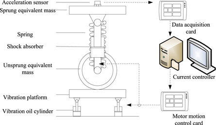
Figure 6. Schematic diagram of the experimental environment.
Download figure:
Standard image High-resolution imageThe input/output subboard was connected with the motor movement control card and driver, and the excitation unit was designed. Then, the shock absorber, current controller, grating ruler, and computer platform were connected, and the fuzzy PID control algorithm was implemented in the controller, completing the development of the fuzzy control method and experimental environment.
3.2. Experimental parameter setting
The random road input module was established through the Simulink simulation module to reflect the performance of the shock-absorber damping fuzzy PID control method, as depicted in figure 7.

Figure 7. Random road input module.
Download figure:
Standard image High-resolution imageThe random road input module was used to refer to the common road surface for automobiles, and the Class B and C road surfaces were equipped. The roughness coefficients of the two roads were set as 64 × 10-6 m2/c/m and 2.5 × 10⁻⁶ m2/c/m, respectively, as the basis for subsequent control tests. The spatial-spectral density function of road roughness were set as follows:

In Formula (12),  represents the spatial frequency,
  denotes the standard spatial frequency, and
  is the frequency index.
Under the same random road surface conditions, the sample set is a random process marked as  The random signal generated according to the time change in the stochastic process is marked as
  (i.e.,
  ). The time history of a random signal is presented in figure 8.
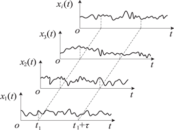
Figure 8. The time history of a random signal.
Download figure:
Standard image High-resolution imageThe damping parameters for the air suspension shock absorber and PID fuzzy controller parameters in this experiment are presented in table 2. The PID parameters were set in the time interval condition of proportional, integral, and differential parameters to adjust the three parameters adaptively to achieve the PID parameter setting.
Table 2. Experimental parameters.
| Type | Item parameters | Parameter value |
|---|---|---|
| Damping parameters of electrically controlled air suspension shock absorber | Equivalent mass of spring load (kg) | 250 |
| Suspension stiffness (kN/m) | 25 | |
| Damping coefficient (N·s/m) | 500 | |
| Nonspring load mass (kg) | 65 | |
| Equivalent tyre stiffness (kN/m) | 300 | |
| PID Fuzzy controller parameters | Initial proportional control parameters (KP0) | 2.2 |
| Initial integral control parameters (KP0) | 0.05 | |
| Initial differential control parameters (KP0) | 0.5 | |
| Scaling factor | 0.5 | |
| Theory of domain range | [−1,1] |
The experimental parameters were set as presented in table 1. The PID fuzzy controller parameter simulation model was built based on these parameters.
3.3. Building a simulation model
The establishment of the simulation model was based on the background of a Class C random road surface. The vehicle running speed was set at 30 km h−1, and the road excitation coefficient was set at 1. The damping fuzzy PID control simulation model of the air-suspension shock absorber was constructed in the simulation environment. The specific simulation structure is presented in figure 9.
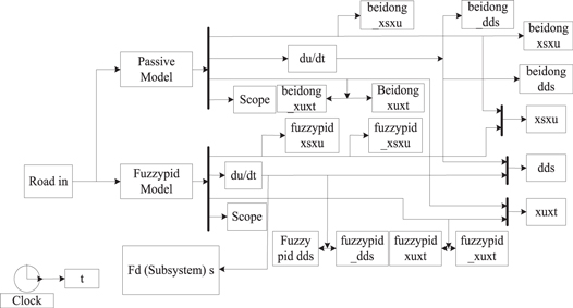
Figure 9. Fuzzy PID control simulation block diagram.
Download figure:
Standard image High-resolution imageThe block diagram of the fuzzy PID control simulation program was analysed, and the step size was calculated according to the input setting information to complete the control force setting, reduce the elastic resistance and viscous damping, and improve the accuracy of the controller position setting and convenience of operation. The simulation program was connected with the function module of the output display to enhance the experimental results. The vehicle vibration was displayed on the computer screen after applying the damper control method, makings it convenient to analyse the application performance of the proposed method.
3.4. Analysis of experimental results
The body amplitude is shown in figure 10. When the body vibration frequency ranges from 5 to 40 Hz, the body amplitude ranges from 3 to 18 mm. According to the body amplitude ranges, the X-axis and Y-axis frequency response functions (FRF) are obtained as shown in figure 11.
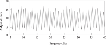
Figure 10. Body amplitude.
Download figure:
Standard image High-resolution image
Figure 11. X-axis and Y-axis frequency response functions.
Download figure:
Standard image High-resolution imageWith the increase of frequency, the frequency response functions of X-axis and Y-axis also change, and the frequency response functions between the two axes are corresponding to each other. Moreover, the peak value occurs when the frequency is about 15 Hz.
First, the vehicle was set up on the Class C road, running at a speed of 30 km h−1. The design method in this paper was used to carry out the damping-control of the shock-absorber of the electronic controller suspension. At the same time, the method by Ding et al [3] and Gao et al [4] were used to compare the same input road profile. The input profile was obtaind according to the vehicle motion datas when the body contacted the road surface. The RMS values of the body vibration acceleration using different methods were compared. The shock-absorber damping-control results are presented in figure 12.

Figure 12. Comparison of the RMS values of the body vibration acceleration on a Class C road surface after applying various methods.
Download figure:
Standard image High-resolution imageIn figure 12, as the experiment continued for longer, the variation trend of the RMS value of body vibration acceleration was similar after applying various control methods. The RMS values of the body vibration acceleration of the methods by Ding et al [3] and Gao et al [4] were 0.11 km h−2 and 0.05 km h−2, respectively. However, after applying the proposed shock-absorber damping-control method, the RMS value of the body vibration acceleration was approximately 0.02 km h−2. Compared with the application effect of the existing methods [3, 4], the RMS of body vibration acceleration reduced by 46.56% and 31.21%. In addition, the RMS of body vibration acceleration results for the methods by Ding et al [3] and Gao et al [4] has relatively large fluctuations. Compared with those methods, the RMS of body vibration acceleration in the proposed design method has relatively small fluctuations on the Class C road surface. Furthermore, the vehicle ride comfort of the proposed design method is high.
Then, the vehicle was set up on the Class B road at the same speed. The proposed design method for the suspension shock-absorber damping-control electric controller was compared with existing methods. The RMS values of the body vibration acceleration after different methods were compared, and the comparative results of the shock-absorber damping control are illustrated in figure 13.

Figure 13. Comparison of the RMS values of the body vibration acceleration on a Class B road surface after applying various methods.
Download figure:
Standard image High-resolution imageIn figure 13, for the proposed electronically controlled air-suspension shock-absorber damping-control method, the RMS values of the body vibration acceleration were higher overall because the Class B road experiment continued for longer than that for the Class C road. The RMS values of the body vibration acceleration of the methods by Ding et al [3] and Gao et al [4] were 0.12 and 0.07 km h−2, respectively. However, after using the proposed method, the RMS value of the body vibration acceleration was small, about 0.05 km h−2, compared with two other control methods, reduced by 40.25% and 29.98%. In addition, the RMS values of the body vibration acceleration by Ding et al [3] and Gao et al [4] have relatively large fluctuations. Compared with these two methods, the RMS value of the body vibration acceleration in the proposed design method fluctuates relatively little on the Class B road surface. Thus, the proposed design method can effectively improve vehicle ride comfort.
Finally, the vehicle running speed was set to 60 km h−1 on the Class B and C road surfaces to verify the control effect of the proposed method against those proposed by Ding et al [3] and Gao et al [4]. The comparison results are presented in table 3.
Table 3. Comparison of the root mean square values of the body vibration acceleration at 60 km h−1.
| Root mean square of vertical body vibration acceleration (km h−2) | ||
|---|---|---|
| Control method | Class B road | Class C road |
| Article design method | 0.022 | 0.028 |
| Ding et al [3] | 0.049 | 0.052 |
| Gao et al [4] | 0.041 | 0.043 |
According to table 3, after the vehicle running speed reaches 60 km h−1, vibration absorber damping control is conducted using the proposed design method on Class B and Class C road surfaces so that the RMS values of the body vibration acceleration were 0.022 and 0.028 km h−2, respectively. Compared with the control effect for the methods proposed by Ding et al [3] and Gao et al [4], when the vehicle running speed reaches 60 km h−1, the RMS values of the body vibration acceleration were 0.049 and 0.041 km h−2 on the Class B road surface, and 0.052 and 0.043 km h−2 on the Class C road surface, respectively.
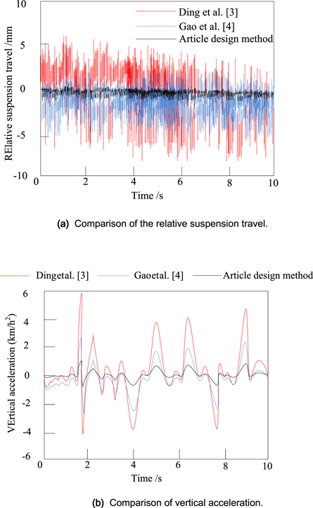
In order to test the control effects of three methods on a quarter of the vehicle, relative suspension travel and vertical acceleration are taken as measures, and the test results are shown in figure 14.
Figure 14. Comparison of relative suspension travel and vertical acceleration of a quarter vehicle.
Download figure:
Standard image High-resolution image
As can be seen from figure 14(a), with the increase of time, three methods' relative suspension travel fluctuated, but the fluctuation of the design method in this paper was small and maintained at about 0. The relative suspension travel ranges of methods by Ding et al [3] and Gao et al [4] are 6 ∼ −8 and 2 ∼ −5 mm, respectively, and their fluctuation ranges are larger than that of the design method in the paper. In figure 14(b), the vertical acceleration values of the three methods also vary. The vertical acceleration ranges of the methods by Ding et al [3] and Gao et al [4] are 6 ∼ −4 and 3 ∼ −2.5 km h−2, respectively. The vertical acceleration of the design method in this paper ranges from 1 to 0.5 km h−2, which is less than that of the comparison methods, proving that the design method in this paper has a good control effect on the body vertical acceleration.
According to ISO 2631, the 'Human body under the whole-body vibration evaluation guide' comfort evaluation, during vehicle operation, the vibration frequency range between 4 and 8 Hz can produce discomfort in human organs, and when the vibration frequency is between 8 and 12 Hz, human spine discomfort increases. In the experimental results, when the speed was 60 km h−1, the RMS values of the body vibration acceleration of the design methods in this paper and the papers by Ding et al [3] and Gao et al [4] were 0.028, 0.052, and 0.043 km h−2, respectively. When the speed was 30 km h−1, the RMS values of the body vibration acceleration of these three respective methods on the Class C road were 0.02, 0.11, and 0.05 km h−2, respectively. As the speed of the vehicle increased, so did the vibration frequency. When the frequency weighted RMS and vibration dose value (VDV) increased, the discomfort of human body was strengthened. At different speeds, the RMS values of the body vibration acceleration of the design method in this paper were lower than the RMS values for the methods by Ding et al [3] and Gao et al [4], proving that the design method in the paper has better vehicle ride comfort. Thus, the proposed damping-control method for electronically controlled air-suspension shock absorbers, which combines fuzzy control technology and PID control algorithm, considerably improves vehicle ride comfort.
Thus, the proposed damping control method for electronically-controlled air suspension shock absorbers, which combines fuzzy control technology and PID control algorithm, considerably improves vehicle ride comfort.
4. Conclusions
Electronically controlled air suspension is an important aspect of intelligent suspension development, which began to be applied in the automotive field a few years ago. However, suspension control technology has not been comprehensively studied, particularly the control of electronically controlled air-suspension shock absorbers. A new fuzzy PID control method was designed by combining fuzzy control technology with the PID control algorithm to mitigate the shortcomings of traditional PID control technology. Adjusting the damping coefficient increased the suspension performance, and the PID control theory improved the control precision. The calculation theory of the domain adaptive scaling factor reduced the detection error. In addition, the particle swarm optimisation algorithm improves the parameter setting speed, and the fuzzy PID control of the shock absorber of the electrically controlled air suspension was realised, improving vehicle ride comfort. In addition, according to the results of the simulation experiments, applying the proposed control method greatly reduces the RMS value of the body vibration acceleration during driving, indicating the effectiveness of the fuzzy PID control theory studied in this paper.
Data availability statement
The data that support the findings of this study are available upon reasonable request from the authors.
Funding
This study was supported by the Key Project of Natural Science Research in Universities of Anhui Province(KJ2020A0625, KJ2020A0626 and KJ2021A0946), Opening Project of Key Laboratory of Electric Drive and Control of Anhui Higher Education Institutes(DQKJ202006), Key project of Natural Science Research in West Anhui University(WXZR202021), and the Domestic Study Project for Teachers of West Anhui University(wxxygnfx2021005).