
Abstract
A novel piezoelectric shunt damping methodology for structures featuring different mode families with high modal density is introduced in this work. To this end, multiple digital vibration absorbers comprising each a voltage sensor, a digital processing unit and a current injector are connected to multiple piezoelectric transducers bonded to these structures. The digital absorbers mimic a multi-stage current blocking shunt circuit whose parameters are determined in a sequential manner to account for the interaction between the different branches. Two tuning strategies which target either an actual resonance frequency of a mode family or a so-called mean frequency are developed and compared, and their robustness to mistuning is addressed. The use of these tuning strategies in combination with the multi-stage shunt design allows to target multiple mode families at the same time. Finally, the theoretical developments are demonstrated experimentally on a 3D-printed rail with 5 blades.
Export citation and abstract BibTeX RIS
Nomenclature
| ωoc | Open-circuit resonance frequency |
| ωsc | Short-circuit resonance frequency |
| Kc 2 | Electromechanical coupling factor (EMCF) |

| Mean electromechanical coupling factor (MEMCF) |

| Mean open-circuit resonance frequency |

| Capacitance of the piezoelectric patch p under constant strain |
| L | Shunt branch inductance |
| R | Shunt branch resistance |
| s | Laplace variable |
| Cp (s) | Dynamic capacitance |
| Ep (s) | Dynamic elastance |
| Vp | Voltage across the electrodes of a transducer p |
| qp | Charge of piezoelectric transducer p |

| Current of piezoelectric transducer p |
| Vs | Voltage across a shunt branch |
| qs | Charge of a shunt branch |

| Equivalent capacitance seen from a specific shunt branch |

| Equivalent open-circuit resonance frequency seen from a specific shunt branch |

| Equivalent short-circuit resonance frequency seen from a specific shunt branch |

| Network inductance |

| Network resistance |
| R* | Optimal resistance of a fictitious shunt branch |
| L* | Optimal inductance of a fictitious shunt branch |
| Z | Shunt impedance |
| VADC | Voltage input to a digital unit |
| VDAC | Voltage output of a digital unit |
| α | Piezoelectric voltage division ratio |
| β | Amplification gain |
| γ | Attenuation gain |
| δc | Factor representing the imperfections of the DVA |
| gc | Current source gain of the DVA |
1. Motivation and state of the art
The attenuation of structural vibrations is a popular and continual challenge for engineers in many disciplines. In mechanical engineering, piezoelectric shunt damping represents an effective solution for damping enhancement. In this approach, piezoelectric transducers are used to convert mechanical energy into electrical energy. By connecting them to a shunt circuit, a part of this electrical energy can then be dissipated [1, 2]. Popular circuit designs consist of branches with properly-tuned inductors and resistors (in series or in parallel) that dissipate electrical energy at desired frequencies. Since the optimal values for the inductances are often considerably large and thus difficult to realize with passive analog electrical elements, virtual inductors are commonly used [3]. Other approaches propose a fully digital realization of the desired electrical shunt circuit through a digital vibration absorber (DVA) [4]. A DVA is a versatile device that can be easily adapted to the application at hand, e.g., for nonlinear vibration mitigation [5].
The problem of targeting multiple modes of a structure with one or several piezoelectric shunts has already been addressed in literature. There exist various circuit designs for multimodal damping with a single transducer, such as Hollkamp's layout of parallel RLC branches, current blocking or current flowing circuits and they were emulated by DVAs [6–10]. Other approaches tackle the problem from a control design perspective [11].
In general, multimodal circuits can prove hard to tune, which is why Berardengo et al presented a new approach to design an optimal multimodal piezoelectric shunt impedance that was based on matrix inequalities [12]. Recently, Dal Bo et al introduced a design tool for electrical shunt circuits targeting multiple modes that aims for circuit designs with a few elements [13]. Focusing now on approaches exploiting multiple transducers, Moheimani et al designed a decentralized multiport synthetic impedance shunted to multiple piezoelectric elements [14]. An alternative tuning approach was proposed by Giorgio et al who used a digital implementation of a shunting admittance that targeted multiple modes of one- and two-dimensional structures. They designed a multiterminal network that interconnected multiple piezoelectric transducers aiming to be equivalent to a set of single transducers so that common tuning rules for the electrical parameters could be used [15, 16]. Rosi et al exploited the same approach for the control of sound radiation and investigated the optimal placement of the piezoelectric transducers when targeting multiple modes. Their approach was based on the optimization of the modal controllability [17, 18]. Recently, Toftekær and Høgsberg proposed a multimodal resonant piezoelectric shunt calibration method that takes the influence of non-resonant vibration modes into account [19].
So far, all these multimodal damping approaches were demonstrated numerically or experimentally on structures with low dimensionality such as beams or plates but not yet on more complex structures. To progress toward this direction, the objective of this work is thus to demonstrate experimentally the mitigation of the resonant vibrations of structures featuring different mode families with high modal density. The structure of interest in this study is a so-called bladed rail. It consists of a support structure (rail) with five blades and has dynamic properties similar to bladed disks. The bladed rail modes appear in groups featuring closely-spaced frequencies, the so-called mode families. The complexity of this structure requires a challenging and accurate identification of the piezoelectric structure and the electromechanical properties. To our knowledge, a digital shunt has not yet been used on a complex mechanical structure. In this work, several digital shunts were used simultaneously and an identification strategy of the resulting electromechanical structure is exploited.
To cope with the high modal density of the bladed rail, the multiple digital absorbers are used to mimic a multi-stage current blocking shunt circuit. Due to the fact that targeted resonance frequencies can be close to each other, difficulties can be encountered using common multimodal shunt designs. To address this problem, two tuning strategies, namely the isolated-mode and mean shunt approaches, are introduced. Using the former strategy, one mode per family is damped with one DVA independently. The latter approach takes advantage of the fact that the frequencies of a family of modes are closely-spaced and targets an average frequency per mode family per DVA. When several families of modes are targeted simultaneously, both strategies are implemented using a multi-stage circuit where the electrical elements of the stages are tuned sequentially to take the influence of previous stages into account [10]. Thus, in this work, a multimodal shunt is used in combination with a novel tuning approach to simultaneously target closely-spaced modes of multiple mode families. For the case of the mean shunt strategy mentioned above, this work can be seen as an extension from one to multiple mode families [20].
The paper is structured as follows. Section 2 presents the two aforementioned tuning strategies. The design of the DVA that is used in this work to emulate the transfer function of the piezoelectric shunt is described in section 3. After the introduction of the experimental setup in section 4, we present in section 5 the results of the experimental campaign where we demonstrate the robustness of the tuning strategies as well as their effectiveness in terms of damping performance. The conclusions of the present study are drawn in section 6.
2. Shunt tuning strategies
This section addresses the mitigation of the vibrations of structures featuring different mode families with closely-spaced modes using multiple DVAs, each connected to a single piezoelectric transducer. The case of a single mode family is first discussed followed by the consideration of multiple mode families.
2.1. One mode family
In this case, the vibration of each targeted mode of the family is mitigated using a single series RL shunt. Two different approaches are considered for calculating the values of the different resistors and inductors, namely the isolated-mode and mean shunt strategies. In the isolated-mode strategy, the RL shunt is merely tuned according to the H∞-norm considering the actual resonance frequency of the mode. This is known to provide equal peaks in the receptance function. To derive the optimal shunt parameters according to Soltani et al [21], we introduce the electromechanical coupling factor (EMCF) which is the rate of converted energy by the piezoelectric material and thus different for each piezoelectric transducer. For a given patch p, the EMCF reads

where ωsc,m,p is the mth resonance frequency of the structure when transducer p is in short circuit and every other transducer is in open circuit; ωoc,m is the corresponding open-circuit frequency. Introducing an intermediate parameter

the values for the inductance Lm,p and the resistance Rm,p of a single shunt branch are defined as

and

 is the capacitance of the piezoelectric patch p under constant strain. To maximize performance in terms of vibration mitigation, each shunt is connected to the transducer featuring the greatest electromechanical coupling factor with the targeted mode.
The mean shunt strategy initially proposed by Mokrani [20] adopts a different perspective. Here, each shunt is tuned according to a so-called mean frequency, which is the average of the M targeted resonant open-circuit frequencies ωoc,m

where the M mechanical modes are indexed by m. An average of the EMCF, the mean effective electromechanical coupling factor (MEMCF), over the M modes defined by P transducers can also be defined

Assuming that the structure is unforced (f = 0) and that all other transducers are in open circuit, taking the Laplace transform of the mechanical equation and inserting it into the electrical equation (cf equation (A.1)) we obtain a dynamic relation between Vp and qp , the dynamic capacitance Cp (s), or its inverse, the dynamic elastance Ep (s) [22]:


Here, s is the Laplace variable. For each transducer p, there exists a dynamic capacitance function that gives information about the electromechanical coupling with the modes of the structure (cf equation (A.7)). The dynamic capacitances for all patches can be gathered in a dynamic capacitance matrix with the dimensions P × P. The pth diagonal entry of this matrix for s = 0 gives information about the static capacitance of transducer p:

Finally, the mean shunt tuning rules for each transducer can be defined according to equations (2)–(4) by using Cp,static
and the derived mean parameters  and
and  from equations (5) and (6). By contrast with the isolated-mode strategy, this approach does not need to consider a patch-mode matching based on the EMCF, because each patch is used to damp all the modes of a family.
2.2. Multiple mode families
When different mode families are to be damped, we consider a shunt circuit with multiple branches where each branch resonates with one mode of a family. To avoid an interference between the shunt branches, the multi-staged current blocking approach proposed by Raze et al [10] is exploited in combination with either the isolated or mean shunt tuning strategy. As depicted in figure 1, one stage comprises a RL-shunt branch and a notch filter tuned toward one of the targeted frequencies, in ascending order. The LC-filters ensure that the current flows through the adequate shunt branch and provide an infinite impedance at the non-targeted frequencies.

Figure 1. Electrical circuit for the multistage current blocking approach tuned toward N resonant modes. One stage consists of a the shunt impedance ZN and a notch filter.
Download figure:
Standard image High-resolution imageThe shunt parameters are determined by a sequential tuning of the different circuit stages [10]. As illustrated in figure 2, this is achieved by identifying an equivalent piezoelectric structure and a fictitious optimal shunt at each stage n of the network. Considering the electrical network from the respective shunt branch point of view and using the two-port network theory [23], the relation between this shunt branch and the piezoelectric transducer can be expressed using a transfer matrix G:

Vs is the voltage across the shunt branch and qs the charge of it. From equation (10), the dynamic elastance Es seen from the regarded shunt can be derived

Assuming that this expression is similar to equation (8) for a single transducer p, we can approximate equation (11) around a specific resonance frequency as

where  ,
,  and
and  are the characteristics of an equivalent dynamic elastance seen from the regarded shunt branch n. They belong to the equivalent piezoelectric structure in figure 2. To be more accurate, an inductance
  and a resistance
  can be added to the transfer function

where  and
and  are the parameters of the equivalent piezoelectric structure (cf figure 2) as seen from the nth
shunt branch. They can be identified by fitting the true elastance in equation (11). For more mathematical details about the identification procedure, the reader is referred to Raze et al [10]. In the mean shunt case, these characteristics need to be calculated for every mode of the family and then averaged according to equations (5) and (6). Similarly, an average of the parameters
are the parameters of the equivalent piezoelectric structure (cf figure 2) as seen from the nth
shunt branch. They can be identified by fitting the true elastance in equation (11). For more mathematical details about the identification procedure, the reader is referred to Raze et al [10]. In the mean shunt case, these characteristics need to be calculated for every mode of the family and then averaged according to equations (5) and (6). Similarly, an average of the parameters  and
and  must be taken.

Figure 2. Schematics of the tuning procedure for the multimodal current blocking approach. The circuit can be regarded in two parts: an equivalent piezoelectric structure and a fictitious optimal shunt that is to be tuned.
Download figure:
Standard image High-resolution imageFinally, the optimal parameters of the shunt branch are calculated by means of the equivalent piezoelectric structure. From the knowledge of  ,
,  and
and  , the isolated-mode and mean shunt strategies described previously can be used to obtain the optimal shunt parameters R* and L* of the nth
fictitious shunt branch. Once the parameters of the fictitious shunt circuit are determined, the physical shunt parameters are given by [10]:
, the isolated-mode and mean shunt strategies described previously can be used to obtain the optimal shunt parameters R* and L* of the nth
fictitious shunt branch. Once the parameters of the fictitious shunt circuit are determined, the physical shunt parameters are given by [10]:

The tuning process is repeated for all subsequent branches of the shunt until all shunt parameters are determined. Using this tuning procedure of a multimodal shunt circuit together with the mean shunt strategy displays a novelty and enables to exploit the mean shunt on two mode families at the same time.
3. The digital vibration absorber
The practical realization of the multiple multi-stage current blocking shunt circuits resulting from the developments in section 2 may be complicated in view of the numerous electrical components present in the circuits. This is why DVAs [4] are used as an effective alternative herein. A DVA comprises an analog circuit and a digital unit emulating the desired input-output (I/O) relation. One DVA is connected to one piezoelectric patch and functions either as a monomodal or multimodal shunt. It measures a voltage Vp
from the piezoelectric transducer and injects the desired current  via the prescribed I/O relation.
Figure 3 shows the design of the DVA used in this work. The design is based on Howland's current source [24]. The resistors Rp,1 and Rp,2 are introduced to reduce the high piezoelectric voltages by a factor α in order to avoid saturation of the operational amplifiers (OA):

The input and output voltages of OA1 are identical and are fed to the ADC They are given by

We introduce an amplification gain

and an attenuation gain

When using the ideal OA assumption [24], it can be shown that the injected current is a function of the DAC voltage as well as the load voltage given by the following relations:

Here, gc
is a current source gain of the DVA. In the ideal case, δc
should be zero so that the current is only driven by VDAC
. Thus, the resistances are adjusted to closely approach δc
= 0 but it is in general not possible to enforce this condition exactly. However, this non-ideal behavior can be compensated by a modification of the I/O relation implemented in the digital unit. If δc
= 0, we would set  , where
  is the current to be injected in the transducer. Now, if the DAC voltage is expressed as

according to equations (16) and (19), the current injected into the load is in fact  . The parameter δc
/(gc
α) can be determined by a simple test when the transducer is replaced by an open circuit (
. The parameter δc
/(gc
α) can be determined by a simple test when the transducer is replaced by an open circuit ( ). Equations (16) and (19) yield

Thus, δc /(gc α) is given by the constant relation between VADC and VDAC in open circuit.

Figure 3. Circuit diagram of the digital vibration absorber (DVA).
Download figure:
Standard image High-resolution imageThis DVA design allows to control the currents in each piezoelectric transducer even if they have a common electrode and prevents an interaction between the DVAs when multiple of them are used simultaneously.
In this work, the circuit that is mimicked in the controller is a passive one which means that the control law is unconditionally stable in theory. However, sampling delays incurred by the digital unit may cause instabilities. The shunt parameters can then be adjusted to avoid them [25].
4. Experimental setup
The tuning strategies introduced in section 2 were demonstrated experimentally through the use of multiple DVAs. The structure of interest is a 3D-printed steel rail with 5 blades, a simplified version of a bladed assembly, which, however, features similar dynamical properties, namely very low damping and different mode families with relatively high modal density. The proposed DVA-based damping strategy could be an effective replacement of the solutions traditionally used in monolithic bladed assemblies, e.g., friction ring dampers whose design is challenging [26] or viscoelastic materials whose effectiveness vary with temperatures [27].
The bladed rail was the subject of previous numerical investigations [28, 29]; it is displayed in figure 4. Different pictures of the experimental set-up are shown in figures 5 and 6. The geometrical properties of the blades were chosen following current state-of-the-art bladed disk designs [20]. The rail structure was clamped at both ends of the support by 3D-printed clamps made of PLA and fixed on an optical table. Five PIC151 (10 mm × 15 mm × 0.5 mm, Physik Instrumente) piezoelectric patches were bonded with conductive glue to the underside of the rail where high strains are expected. Patch #i is connected to DVA #i, i = 1,...,5 (see figure 7). An overview of the patch arrangement in relation to the blade shape is presented in figure 8. It should be noted that the dimensions of the structure cannot be disclosed for industrial confidentiality reasons. The controller board MicroLabBox from dSPACE and the associated software were used to realize the desired transfer function of the digital shunts. An acoustic sine-sweep excitation was applied to excite one or two mode families of the bladed rail. The Headrush FRFR-108 Active Monitor speaker was used for the acoustic excitation (cf figure 6(b)). The velocity at the first tip blade was measured using a laser vibrometer, and the results were post-processed with the Simcenter Testlab software.

Figure 4. The bladed rail structure clamped to an optical table.
Download figure:
Standard image High-resolution image
Figure 5. Prototype of the DVA used in the experimental campaign.
Download figure:
Standard image High-resolution image
Figure 6. Experimental setup for the experiments with the bladed rail. The five patches of the rail were connected to five DVAs (a). For acoustic excitation, the speaker in the background was used (b).
Download figure:
Standard image High-resolution image
Figure 7. Schematics of the experimental setup: Five piezoelectric patches are glued to the bottom of the support structure at the locations of the blade roots. The patches are each connected to one DVA. The DVAs are grounded.
Download figure:
Standard image High-resolution image
Figure 8. Layout of the experimental bladed rail with five piezoelectric patches glued on the rail at the locations of the blade roots.
Download figure:
Standard image High-resolution imageIn order to analyze the structure's dynamics, the open-circuit frequency response function (FRF) of a blade tip was measured. To this end, the electrodes of the piezoelectric patches were disconnected from the DVAs, and a sine-sweep excitation was used over the frequency range of two mode families, i.e., the first bending and first torsion modes. Previous numerical simulations with a finite element model served as the basis for this characterization of the mode families [30]. In the frequency ranges of the mode families, the sweep rate of the excitation was 0.5Hz s−1 whereas a faster sweep, 10 Hz s−1, was chosen over the other frequencies since the focus of this study is not on the support modes of the structure. Figure 9 displays the FRF of the first blade. The first bending mode family (mode family one) appears between 0.29 and 0.33, and the first torsion mode family (mode family two) between 0.79 and 0.83. Although five modes should be visible for each family (one mode per blade), only four resonance peaks were visible for family 1. This can be attributed to the experimental setup but did not pose a problem since it could be taken into consideration in the tuning process.

Figure 9. Open-circuit FRF of the first blade under a sine-sweep acoustic excitation.
Download figure:
Standard image High-resolution imageTo obtain the dynamic elastances Ep (cf equation (8)) between the voltage Vp and the charge qp of the transducer in figure 10, a multisine excitation over the full frequency range was used and realized via currents injected in the patches by the DVAs [31]. A state-space model of the measured dynamic elastances for each patch was then obtained through the PolyMAX modal parameter estimation method [32]. The PolyMAX method provided the structural resonance frequencies in table 1 as well as the damping ratios (on the order of 0.02%). Given the small identified damping ratios, the damping was neglected in this work and not accounted for in the tuning procedure. For the case that the assumption of no damping is not valid, there exist methods in the literature to take damping into consideration during the shunt tuning [33]. The electrical coupling between the modes and the patches was then evaluated by means of the electromechanical coupling factor (cf equation (1)). The zeros (poles) of the dynamic elastances are the short- (open-) circuit resonance frequencies of the electromechanical structure. If the zeros and poles are clearly visible in the transfer function, there is a significant electromechanical coupling between a patch and the considered mode. Each mode is targeted by the patch with which the electromechanical coupling is the strongest, as shown in table 2. Since only four modes were visible for mode family one, the fourth mode was targeted by two patches at the same time.

Figure 10. Dynamic elastance of the five piezoelectric patches (P1—P5): full frequency range (a) and close-up view on the first mode family (b).
Download figure:
Standard image High-resolution imageTable 1. Normalized resonance frequencies of the first and second mode families.
| Family 1 | Family 2 |
|---|---|
| 0.3143 | 0.7943 |
| 0.3213 | 0.8146 |
| 0.3240 | 0.8200 |
| 0.3243 | 0.8237 |
| — | 0.8257 |
Table 2. Patch distribution per mode family.
| Mode family 1 | |
|---|---|
| Mode | Patch |
| 1 | 5 |
| 2 | 4 |
| 3 | 3 |
| 4 | 2 & 1 |
| — | — |
| Mode family 2 | |
|---|---|
| Mode | Patch |
| 1 | 1 |
| 2 | 5 |
| 3 | 3 |
| 4 | 4 |
| 5 | 2 |
5. Experimental results
5.1. Performance of the digital shunts
The first mode family was considered initially so that the DVAs implement a single series RL-shunt circuit. Figure 11 presents the FRF of the bladed rail under sine-sweep excitation in open circuit as well as shunted according to the two tuning approaches. Substantial resonance amplitude reductions could be obtained. For mode 1, the isolated-mode and mean shunt strategies could lead to a reduction of 14 and 8 dB, respectively. The performance of both approaches was equivalent for the second mode (19 dB). For modes 3 and 4, the isolated-mode and mean shunt strategies achieved a reduction of 8 and 12 dB, respectively. The mean shunt strategy could provide better mitigation of the third and fourth modes because the mean frequency is located in their vicinity. Another reason is that the performance of the isolated-mode strategy may somewhat deteriorate when modes are closely-spaced.

Figure 11. FRF of the first mode family of the bladed rail: open circuit, shunted by the isolated-mode or mean shunt strategies.
Download figure:
Standard image High-resolution image5.2. Robustness of the digital shunts
5.2.1. Modification of the digital controller frequencies
To assess the robustness of the digital shunts, the optimal frequencies of the digital shunt were perturbed up to ±10%. The H∞ (maximum FRF amplitude) and H2 (area under the FRF curve) norms of the FRF are depicted in figure 12. The isolated-mode strategy offers the best performance when the frequency factor is 1.01 (different from 1 due to the slight time variability of the set-up). However, a better and smoother evolution of the mean shunt performance is observed for other frequency factors. Overall, it can be concluded that the two shunts remain effective up to a detuning of approximately 5%. For greater detuning, the DVAs can even have a (small) detrimental effect on the dynamics.

Figure 12.
H∞ (a) and H2 (b) norms of the FRF for the first mode family of the bladed rail for different shunt frequencies. The isolated-mode ( ) and mean shunt (
 ) strategies are compared to the open circuit case (- - -).
Download figure:
Standard image High-resolution image5.2.2. Modification of one blade
Physical modifications were also brought to the bladed rail. An additional mass in the form of magnets was added to the first blade, as illustrated in figure 13. With the added magnets, approximately 45% of the blade mass was added. The modifications caused a shift of the first resonance frequency of mode family one by 2.7% and had only a slight effect on the other resonance frequencies. Figures 14 and 15 compare the measured FRFs with the detuned shunts and with the shunts retuned according to the new resonance frequencies. Whereas the isolated-mode strategy could successfully be retuned, the retuned mean shunt provided an attenuation of the first resonance amplitude of less than 1 dB. This can be explained by the relatively far distance of mode 1 from the other modes. On the other hand, the direct comparison of the two approaches in figure 15 highlights that the mean shunt provides a more robust damping performance on the other modes of the family than the isolated-mode strategy.

Figure 13. Modification of the bladed rail. A pair of magnets was added to the first blade in order to change the resonance frequencies of the blade modes.
Download figure:
Standard image High-resolution image
Figure 14. Robustness study (first blade mass modified): isolated-mode (a) and mean shunt (b) strategies.
Download figure:
Standard image High-resolution image
Figure 15. Robustness study (first blade mass modified): comparison of the two approaches.
Download figure:
Standard image High-resolution image5.2.3. Modification of five blades
Magnets were finally added to all five blades of the structure, resulting in a decrease in resonance frequencies for the first mode of 3.6%. Figure 16 evidences that the locations of the magnets were different for each blade to model a non-uniform structural mistuning. Figure 17 presents the measured FRFs for the detuned and retuned shunts. As before, the isolated-mode strategy could successfully be retuned. In contrast, whereas the retuning was effective for the mean shunt for modes 2 and 3, it only led to a slight improvement for mode 1 and an increase in the resonance amplitude for mode 4. This is caused by the fact that mistuning increased the distance between modes 3 and 4 that and mode 1 is still relatively far from the other modes. It can thus be concluded that the mean shunt strategy is not necessarily robust when the resonance frequencies are not very close to each other.

Figure 16. Modification of the bladed rail. A pair of magnets was added to each blade.
Download figure:
Standard image High-resolution image
Figure 17. Robustness study with all blades modified: isolated-mode (a) and mean shunt (b) strategies.
Download figure:
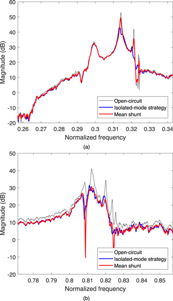
Standard image High-resolution image5.3. Vibration mitigation of two mode families
To mitigate the vibrations of the first two mode families, one mode per family is targeted by a single DVA, which thus emulates a two-stage current blocking circuit.
The results are displayed in figure 18. The amplitudes at resonance of the second mode family could be attenuated by approximately 10 dB, with a somewhat lower performance for the first mode family particularly for the mean shunt approach. The more uniform and superior damping performance in the second family is partly due to the fact that its modes are more equally distributed in the frequency range than in the first mode family. We also mention that considering an additional mode family can lead to an overall decrease in damping performance. Indeed, the optimal current flow might not be guaranteed when the complexity of electrical circuit increases. Specifically, a part of the current might flow through other branches than the desired one.
Figure 18. FRF of the bladed rail structure with open-circuited patches or shunted with current blocking circuits in the range of the first (a) and second (b) mode families.
Download figure:
Standard image High-resolution image
6. Concluding remarks
This paper introduced a new piezoelectric shunt tuning methodology for complex mechanical structures featuring different families/groups of modes with potentially high modal density. The experimental demonstration was greatly facilitated by the use of multiple DVAs connected to the host structure through piezoelectric transducers. To this end, a thorough identification of the electromechanical system was conducted. The results obtained on a bladed rail evidenced that the vibrations of as many as 9 modes could be reduced with attenuation factors ranging from 5 to 18 dB depending on the mode or tuning strategy considered. A detailed robustness analysis showed that the shunts remain effective against changes up to 5% of the resonance frequencies. The retuning of the shunts could be easily carried out thanks to the flexibility of piezoelectric shunts realized by DVAs.
Acknowledgments
The authors J. Dietrich, G. Raze and G. Kerschen would like to acknowledge the financial support of the SPW (WALInnov grant 1 610 122).
Data availability statement
All data that support the findings of this study are included within the article (and any supplementary files).
: Appendix. Basic electromechanical equations
Models of electromechanical structures can e.g. be obtained by using the finite element method [1]. With a vector of K generalized mechanical degrees of freedom (DoFs) x, the vector of generalized mechanical loading f, the voltage across the electrodes of the transducer Vp
and the current flowing through it  , the governing equations of a piezoelectric structure read

Here, M is the structural mass matrix, Ksc the structural stiffness matrix with the electrodes of the transducer in short-circuit and γ p represents an electromechanical coupling vector. The Laplace transform of equation (A.1) is

Or, with the voltage Vp as an independent variable:

where

Using a matrix of short-circuit mode shapes Φsc, and a diagonal matrix Ωsc with short-circuit resonance frequencies, we obtain the following relations:

The expression for the dynamic capacitance in this multimodal case can be obtained for an unforced structure (f = 0) by condensing the mechanical equation into the electrical one using equations (A.2) and (A.5). Eventually, the dynamic capacitance reads


with the modal coupling coefficients γϕ,n given by
