
Abstract
Research is now being done on soft electroactive polymers (EAPs), such as polyvinyl chloride (PVC) gel, as an example, for use in soft robotics and smart sensors. Although the sensing behavior of PVC gel has not yet been thoroughly investigated, it has been determined that this material reacts in some way to the stimuli that come from the outside. PVC gels are being utilized to construct a broad variety of different kinds of smart sensors due to the fact that their deformation may be endlessly configured by variations in electrode arrangement, applied mechanical stress, and the amount of plasticizer contained within the gel. In this study, experimental characterizations and the results of finite element simulations are discussed for a PVC gel compression sensor. The finite element simulation of what happens to PVC gel when it is compressed from the outside using mechanical force has been built using the COMSOL Multiphysics, which is a finite element simulation software. Additional experimental measurements of PVC gels are carried out in order to validate the underlying principles that have been presented thus far by providing context for the results of the simulations and to validate the findings effectively. Based on the findings, it appears that the suggested sensor is able to detect compression at a variety of amplitudes and rates . This study sheds light on the sensing capabilities of PVC gel in sensing investigations and provides a framework for conducting such investigations, thereby laying the groundwork for an increase in the use of PVC gel sensors in soft robotics research in the future.
Export citation and abstract BibTeX RIS
1. Introduction
Electroactive polymers (EAPs) have recently sparked a lot of interest in the development of soft actuators [1, 2]. They have the ability to alter shape or size in response to electric stimulation, with benefits such as great actuation strain or stress, stretchability, lower noise, compact size, and manufacturing and processing simplicity [3]. The most prevalent electroactive materials are classified into two kinds: ionic and non-ionic EAPs. Ionic EAPs, which include ionic polymer-metal composites (IPMC), are operated by both ions and corresponding conjugated material dispersion and mobility [4–7]. The drive voltage of the IPMC is very low at a few volts, the response is relatively slow, and the life is limited. The non-ionic EAPs are the second kind of electroactive polymer, which includes dielectric elastomers and electrophilic polymers like annealed plastic gel (namely PVC gel) which are driven by Maxwell force or electric field [8, 9]. Dielectric elastomers hold enormous promise as soft actuators due to their massive deformation (around 4000%), high stress, fast response time, and high power density [3]. Therefore, to get good performance, several thousand volts are usually required, which could pose a safety risk in real applications. Meanwhile, with a relatively low driving voltage, soft actuators comprised of plasticized PVC gel have shown promise in comparable strength, strain, and speed to those of human muscle, as well as good stability and longevity, implying that they have a lot of potential as soft actuators [10, 11].
Poly(vinyl chloride) (PVC) is an electrically inert dielectric polymer that has long been used as an electrical insulator [12]. Plasticization of PVC, on the other hand, produces an electrically active polymer that could be used as an artificial muscle. Because of its distinctive electric field response, PVC gel, or so-called plasticized PVC, a soft jelly-like material, has been widely explored as an electroactive actuator material with a large proportion of plasticizer [13, 14].
PVC gel is a good electroactive polymer material for exploring soft actuators because it has a lot of creep-induced deformation/displacement and a lot of yield stress. It is also good for robotics, devices, quick reaction time, light weight, power efficiency, durability, a remarkably low driving voltage, and it is easy to make and process [15–19].
Many studies and research have been talked about the PVC gel as a soft actuator, such as in [15, 17, 20–24] based on the different boundary conditions of the PVC gel and its electrodes to create a variety of soft actuators with noise-free bending action, tensile movement, extended motion, molecular study, plasticizer thickness, and creep motion. From these studies and more, PVC gel-based soft actuators provide a number of benefits over other soft actuators in terms of practical usage.
There has been few researches talking about the sensing properties of PVC gel. Neubauer et al in [17] demonstrates that PVC gels are a highly sensitive material when it comes to mechanoelectrical transduction, investigate specific response dependency, and present a mathematical model for mechanoelectrical behavior in the PVC gels. The work described here reveals an intriguing phenomenon that occurs during the initial contact with the gel under extremely modest compressive stresses. The outcomes of the study reveal PVC gels' mechanoelectric ability to function in sensing tests and serve as a foundation for expanding the applicability of PVC gel sensors. This work is completely based on the experimental testing on multiple gel pieces and the authors have not proposed any mathematical or numerical model to validate the results.
In this study, we intend to delve into the sensing capabilities of the PVC gels. Compared to the study by Neubauer et al in [17], our study is split into two distinct sections: the experimental and the finite element simulation sections under compressive force. In the experimental investigation, the PVC gel is compressed using a variety of trajectories to investigate the effect of compressive force on the gel sensors' steady-state and dynamic responses. This is done in order to identify how the trajectories affect the responses. The simulation of finite elements is the subject of the next stage of this research. The use of finite element simulation in PVC gel modeling has garnered a comparatively modest level of interest. Because of this, the use of PVC gels in soft robotics applications as smart sensors presents a challenge, since the control of a gel sensor in this context requires the use of a model. The finite element simulation was used to validate the results of the experimental testing.
In order to carry out the suggested model, a three-dimensional finite element time dependent simulation for a PVC gel sensor model that is subjected to compression load stimuli is used. Experiments are also performed to measure the sensor response under compression to the findings of simulations. Additionally, a sweep solution analysis is done to anticipate crucial parameters of the finite element model. The comparison between the experimental measurements and the finite element results demonstrates that the suggested finite element model, which is based on COMSOL multiphysics, is capable of capturing sensor response under a variety of rates and magnitudes of input compression loads. This is demonstrated by the fact that the comparison between the experimental measurements and the finite element results. It has also been shown that the finite element model can precisely predict that the sensor response is entirely determined by whether or not the input load on the sensor is raised or dropped. On the other hand, a model may make predictions about behavior that are dramatically at odds with the evidence obtained through measurements.
As a remainder for the reader, the paper is organized as follows: after the abstract and the introduction, the sensor fabrication is demonstrated in section 2. The experimental characterization, which includes the experimental setup and the sensor characterization of the PVC gel sensor for its sensing response under compression, is explained in section 3. Finite element simulation, which includes simulation setup and simulation results, is shown in section 4. Parameter identification and the related subsection, which is model validation, are explained in section 5. Finally, the conclusion section is provided in section 6.
2. Sensor Fabrication
For the fabrication process of this sensor, we followed the fabrication process in [17]. We used a pure poly(vinyl chloride) powder commercially available with (Mw = 80k g/mol, Mn = 47 k g/mol), dibutyl adipate (DBA) (MW = 258.38 g mol-1) as a plasticizer, finally we used a tetrahydrofuran solution form which has obtained from Sigma Aldrich Co. We mixed the mixture for around 5 hours at 50 °C. The percentage of PVC to DBA plasticizer has been designated to 1-part of PVC over 8-part of DBA plasticizer by weight (often called to as (PVC80) in the literary works) (with around 20 ml of solvent/gram of PVC), after that, cast on a dish made of glass (diameter of 15 cm) for four days, after which the tetrahydrofuran was allowed to fade away in a laminar flow hood at 25° which represents PVC gels were made with a thickness of around 1 mm.
3. Experimental characterization
3.1. Experimental setup
Experiments on the PVC gel were performed using an experimental setup that consisted of a DC motor and a voltage regulator, as well as a very simple microcontroller, namely the Arduino Uno. The voltage regulator and the Arduino Uno were responsible for providing control over the whole system. Because of this ability, a compressive load can be put on the PVC gel sample in a very precise way. Using a stepwise compressive force input, it was possible to examine both the steady state and the transient state sensor responses of the PVC gel sample that was being tested. This force application mechanism was equipped with a Force Sensing Resistor FSR402 to measure the applied force on the PVC gel. The PVC gel was sandwiched between two stain-steal electrodes. The top electrode (the Anode) was in the circular mesh shape whereas the bottom one (the cathode) was in the shape of rectangular sheet. Figure 1 shows the components of the experimental setup, including the 3D printed parts configuration that imposes a linear stimulus on the gel sample, and NI MyRio data acquisition (myRio—1900) to measure the sensing signal from the gel sensor and to measure the applied force.
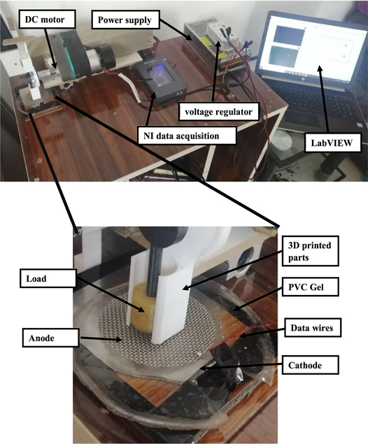
Figure 1. Experimental setup.
Download figure:
Standard image High-resolution image3.2. PVC gel sensor characterizations
In order to investigate the sensor's steady-state and transient characteristics, a set of force stimuli is applied to the PVC gel sensor in order to identify its sensing responses and then analyse those responses. As can be seen in figure 2, the very initial force took the shape of a square trajectory that lasted for a certain amount of time. This type of input is used to determine the general behavior of the sensor, specifically whether or not the signal will be affected by the static (fixed) force, which means that it will decrease or fade over time just like the signal of other sensors, such as the IPMS sensor. This type of input is used to determine whether or not the signal will be affected by the static force. We note that the input force trajectory that we chose allowed us to investigate a wide range of PCV gel sensory behavior, including both steady state (when the input force is held constant) and dynamic behavior during transients, the sensing signal through loading and/or unloading of the input force stimulus. We came to the conclusion that the input force trajectory we chose let us study a wide range of sensory behavior in PVC gel. Figures 3 and 4 further exhibit the sensing response of the PVC gel sensor under the corresponding input force (N). As can be observed from the figures, when the force is applied, the PVC gel sensor gives a sensing response. It is noticeable in the figures 2, 3, and 4 that wherever there is a force applied to the sensor, the sensor emits a voltage (as a sensing response) that has the same trajectory as the applied force, even if the applied force is in an upward or gradual manner and never approaches zero at the steady-state, which it does when the input force becomes zero.
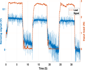
Figure 2. Experimental Results: square input force to the PVC gel in N (red line) and the sensing signal (volts) dotted line.
Download figure:
Standard image High-resolution image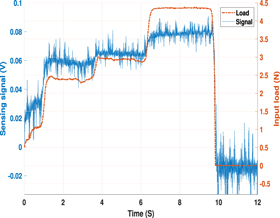
Figure 3. Experimental Results: input force to the PVC gel in N (red line) and the sensing signal (volts) dotted line.
Download figure:
Standard image High-resolution image
Figure 4. Experimental Results: input force to the PVC gel in N (red line) and the sensing signal (volts) dotted line.
Download figure:
Standard image High-resolution imageThese enrichment behaviors provide excellent tests for the proposed sensor. Additionally, as is going to be explored in section 4.1, finite element simulation will be discussed and solved to examine its ability to predict the PVC gel responses under different loading magnitudes.
4. Finite element simulation
4.1. Simulation setup
The sensing responses of the PVC gel sensor model are determined by the PVC sensor's deflection in response to a compression force on the sensor body. A three-dimensional solid-electrostatic module from COMSOL Multiphysics was used to run the finite element simulation and help figure out what happens to the structure of the sensor when a compression stimulus is applied to the proposed sensor model. The geometry and dimensions of the simulated sensor device are close to those of the experimental prototype. In particular, the anode mesh that was used in the experiment measures 2.5 cm in diameter and 0.1 cm in thickness and is attached to the top of the PVC gel. And the cathode, which was a metal plate, has a thickness of 0.1 cm which the PVC gel is placed. The PVC gel has a thickness of 0.1 cm and a diameter of 2.5 cm as shown in figure 5.
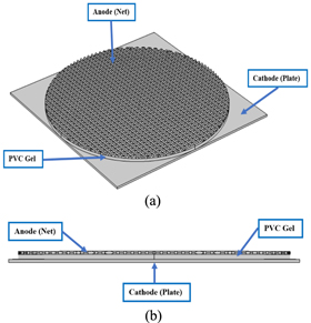
Figure 5. Finite Element Modeling: (a) 3-D modeling top view; (d) 3-D modeling side view.
Download figure:
Standard image High-resolution imageCOMSOL Multiphysics was used to describe the geometry of the sensor model, sensor meshing, and remaining simulation of the sensor model. To link mechanical deformation of the sensor model with electrical effects of the model material characteristics and behavior, the piezoelectric effect (pze) of the three-dimensional multiphysics finite element simulations was used.
The suggested sensor model is simulated using COMSOL Multiphysics modules: solid Mechanics (Solid) and Electrostatics (es). The charge conservation govern equations, which state that the divergence of the electrical-displacement equals the charge density inside the selected material, and the electric potential govern equation, which states that the electrical field is the negative gradient of the electrical potential, can both be found in electrostatic physics.
The generated sensing signal (voltage) due to the applied force to the sensor model is by using the constitutive relation, which is the stress-charge from the piezoelectric material properties in the PVC gel layer. The model is a time-dependent simulation of the effects of an input force with a specific profile. The anode was considered to be subjected to a compression force (N), and the electrodes of the sensor model are considered to be hard.
4.2. Simulation results
4.2.1. 2-D Simulation results
The applied force to the mesh-like structure (Anode) which is attached to the sensor model, which in turn leads to a compression force on the sensor model, produces a strain in the direction of the applied force on the PVC sensor model at the same trajectory of the input force. Figure 6 shows a snapshot of the model structure, including the PVC gel sensor model and the two electrodes, where the force is distributed on the anode (mesh-like structure). From the figure, the anode and the PVC gel model are defecting with respect to the pressure applied to the entire model. Figure 7 shows a snapshot of the generated electric potential as a sensing response in response to the mechanical deflection due to the applied input load as a compression force to the sensor model.

Figure 6. Finite Element Results: mechanical deflection and the mechanical pressure due to the input force to the anode (the mesh-like structure).
Download figure:
Standard image High-resolution image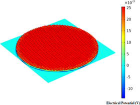
Figure 7. Finite Element Results: the electric potential in response to the mechanical deflection due to the input force.
Download figure:
Standard image High-resolution image4.2.2. 1-D Simulation results
The sensing responses of the sensor, which is the electric potential, are obtained with a sequence of compression force trajectory, to examine its steady-state and transient behaviors. In particular, the first input force trajectory is to apply a force with a specific value and hold it for 5 s and then increase the force (rapid ramping) to the double of the first value and hold it for 5 s and then increase the force (rapid ramping) by the same interval for another 5 s and finally rapid ramp down to zero. Figure 8 shows an example of the input load trajectory (solid red line) and a corresponding sensing signal (blue dotted line). From the figure, one can see that the FE sensing signal follows the load trajectory in terms of loading and unloading. Figure 9 is another example of FE simulation where the input load is a square wave, which represents ramping up (loading) then holding for 5 s and ramping down (unloading) then holding it unloaded for another 5 s and repeating the same period. As in figure 8, the sensing signal, which is the electric potential in figure 9 has the same behavior in regards to the transient and the steady-state corresponding to the input load.
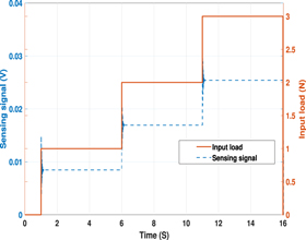
Figure 8. Finite Element Results: a stair-like input load to the PVC gel in N (red line) and the sensing signal (volts) dotted line.
Download figure:
Standard image High-resolution image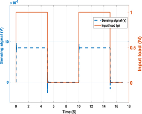
Figure 9. Finite Element Results: square input load to the PVC gel in N (red line) and the sensing signal (volts) dotted line.
Download figure:
Standard image High-resolution image5. Parameter identification
The parameters of the finite element model which are proposed in section 4.1 are obtained and utilized for the validation of the FE model. PVC gel Sensor dimensions such as electrodes diameter and thickness are directly obtained by measurements. In particular, the anode mesh that used in the experiment measures 2.5 cm in diameter and 0.1 cm in thickness. And the cathode which was a metal plate has a thickness of 0.1 cm. The PVC gel has a thickness of 0.1 cm and a diameter of 2.5 cm. These dimensions were used in the simulation as well.
The physical constants of the finite element which include temperature (T) is directly calculated using a thermometer, the density (ρ) of the material is obtained through measuring the sensor volume and weight. The value of Young Modulus G was taken from [16] and set to be 7500 Pa.
The Relative Permittivity  r
was obtained through running a sweep solution via COMSOL multiphyscis software. Here, we selected one of the experimental input load force as the input to the FE simulation which was figure 10 and selected a range of r
values to the sweep solution [5000, 5500, 6000, 6500, 7000] and we compared the output voltage of the PVC gel sensor with the corresponding experimental sensing signal to see the similarity in the magnitude and the behaviors. Figure 11 explains the FE sensing output of the PVC model where the input load to the model is as figure 10. From the figure, it can be seen that the sensing responses of the PVC model are tracking to input load wherever is goes, even if there a small ripple in the movement which confirm the experimental findings.
r
was obtained through running a sweep solution via COMSOL multiphyscis software. Here, we selected one of the experimental input load force as the input to the FE simulation which was figure 10 and selected a range of r
values to the sweep solution [5000, 5500, 6000, 6500, 7000] and we compared the output voltage of the PVC gel sensor with the corresponding experimental sensing signal to see the similarity in the magnitude and the behaviors. Figure 11 explains the FE sensing output of the PVC model where the input load to the model is as figure 10. From the figure, it can be seen that the sensing responses of the PVC model are tracking to input load wherever is goes, even if there a small ripple in the movement which confirm the experimental findings.
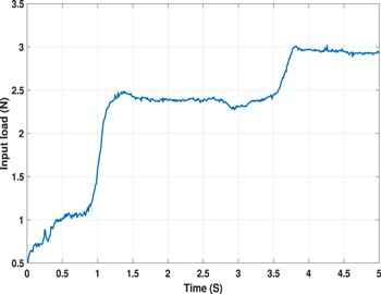
Figure 10. The input signal from the experimental measurements to use it in the simulation to test the model.
Download figure:
Standard image High-resolution image
Figure 11. Finite Element Results: the sensing outputs from the sensor model result from the input load in figure 10 and after a sweep study by using parameter sweep. In this study, we used the relative permittivity to run the sweep study.
Download figure:
Standard image High-resolution imageWe compared the model output with the experimental output and we found that the closest signal that has the relative permittivity of r
5000.
5.1. Model Validation
To validate the FE model, the identified parameter is then utilized in the simulation of the sensor response. In particular, the profile in figure 12 is adopted as an input load to the sensor. Figure 13 compares the measured sensor output to the sensor findings predicted by the finite element model under the inplut load stimuli in figure 12. Generally, the measurement and model prediction are in good agreement. Considering that one of the major model parameters is discovered utilizing only a portion of the data under a certain input load stimulus, the model's validity is supported by the reasonable match across cases. The model, in particular, is capable of capturing the sensor response's magnitude and transients. At steady state, the model correctly predicts that the sensor response will remain constant in magnitude (for a constant load). For the same loading rate, the magnitude of the sensing output increases with the stimulus magnitude.
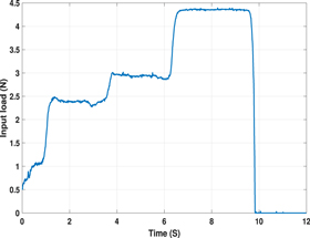
Figure 12. The input signal from the experimental measurements to use it in the simulation to validate the simulation model.
Download figure:
Standard image High-resolution image
Figure 13. The comparison between the finite element output and the measurement.
Download figure:
Standard image High-resolution image
Despite the high level of agreement, there are a few minor differences between the empirical observations and the simulated results, which we attribute to defects in the PVC gel sensor fabrication and the experimental configuration. This can be seen in the experimental curve in figure 13. There is a good agreement in the time between 6–10 s. Other than that, the results shows good but not excellent agreement between the model and the experimental results. The agreement between the experimental data and the model prediction results shows good consistency if one looks at the second half of the figure.
6. Conclusions
An investigation of the fundamentals of sensing behavior in PVC gels was carried out so that the sensing capabilities of PVC gels could be demonstrated. An evaluation is performed utilizing a stepwise loading input in order to assess the sensing response dependencies of a PVC gel piece. When subjected to a greater compression force, the gels exhibited a greater sensing response, and the gel sensor exhibited a sensing response that was comparable to the trajectory of the input load (compression load). A finite element simulation run using COMSOL multiphysics was used to represent the sensing of plate-type and mesh-type PVC gels when they were subjected to compression loads. The findings of the finite element simulation showed a high degree of agreement with the experimental data. In the field of soft robotics, this model will help the PVC gel sensor develop further, and it can also be used to better control sensor properties by changing the amount of load going into the sensor. In future work, we are going to study the physicochemical properties of PVC gels as well as involve the gel in a real robotics applications and we are going to focus on the type of electrodes as in [25], where they discussed many types of electrodes such as wet, dry, and semi-dry electrodes.
Data availability statement
The data that support the findings of this study are available upon reasonable request from the authors.
Footnotes
- *
Montassar Aidi Sharif (M. A. S.) has a PhD degree in Electrical and Computer Engineering from Michigan State University (MSU) - USA. Currently, Dr. Sharif is with the Department of Electronic and Control Engineering and Computer Engineering Departments, Technical Engineering College—Kirkuk, Northern Technical University (NTU), Iraq.