

Abstract
This research article addresses the pitting corrosion resistance of FGM walls fabricated by the Wire Arc Additive Manufacturing (WAAM). The wall is created by layer-by-layer transfer of molten metal in an uninterrupted manner with little heat input using the CMT process. Pitting corrosion tests were carried out as per the ASTM G48-11 standard on the specimens extracted from Inconel 825, FGM interfaces, and SS316L regions of the wall. The specimens were immersed in the ferric chloride hexahydrate solution for 24, 48, and 72 h. It was found that the FGM interface and the specimens made of Inconel 825 were more resistant to corrosion than the SS316L specimens. The weight loss is measured as 0.462 g, 0.1087 g, and 0.1349 g for the SS316L, FGM interface, and Inconel 825 specimens, respectively. Scanning Electron Microscopy (SEM) and Energy Dispersive Spectroscopy (EDS) were used to analyze the corrosion products at the corrosion pit. The order of the pitting corrosion resistance of the specimens extracted from the FGM wall was: FGM interface > Inconel 825 > SS316L.
Export citation and abstract BibTeX RIS
1. Introduction
The development of maritime resources necessitates the use of corrosion-resistant alloys. Such alloys provide the cornerstone for both maritime technology innovation and the development of sustainable marine engineering materials. Therefore, understanding the corrosion behaviour of potential materials for maritime applications is critical. Corrosion products commonly conceal surface pits. A microscopic surface flaw, such as a scratch or a local change in composition, can cause pitting. Although ion diffusion is limited, corrosion penetrates the metal's bulk. It is mainly limited to a few regions. It quickly infiltrates and attacks, making it difficult to detect [1].
In recent years, nickel-based alloys have gained widespread recognition as suitable materials for offshore oil and gas pipelines due to their superior mechanical strength and corrosion resistance compared to steel [2–7]. The microstructural modifications caused by inappropriate manufacturing procedures can result in the formation of different secondary phases [8, 9]. The most common precipitates are secondary austenite, nitrides, MC carbides, and other intermetallic phases. Their presence might cause material degradation, especially in terms of corrosion characteristics [10, 11]. Niobium and molybdenum are considered to be key solid solution strengthening constituents in Inconel 825. During the high-temperature ageing process, they can precipitate as γ' or δ intermetallic phases and carbides, which reinforces the matrix [12]. The diffusion coefficients of Nb and Mo, on the other hand, are less than one. They enhance the inter-dendritic region while diminishing the dendrite core during solidification as a result of their separation from the liquid metal [13, 14]. As a result, the production of intermetallic laves phases in the inter-dendritic area is usually related to the WAAM of Inconel 825. The corrosion behaviour of Inconel 825 welds is influenced by their microstructure. Corrosion occurs mostly in the inter-dendritic region, where Ni and Cr deprivation reduce the protection of the passive layer. The localised corrosion rate of Inconel weld was reported by Cooper to be connected to galvanic corrosion between the inter-dendritic area and the dendrite core [15]. Zahrani believes that the Laves phase was important for the development of pits, which led to the formation of the internal-attacked region [16].
For better performance, corrosion resistant alloys can be functionally graded. Directly combining incompatible materials, on the other hand, might result in thermal expansion mismatches or the formation of intermetallic, which can lead to service failures such fracturing or debonding [17–20]. Fabricating Functionally Graded Materials (FGMs) with various material compositions at the interface layers may help with material adhesion [21]. FGMs (functionally graded materials) are materials with varied chemical, mechanical, thermal, and electrical properties over the volume of the bulk material. Depending on the application, certain FGMs are built as stepwise-graded structures, while others are developed as continuous-graded structures [22–24]. FGMs were made using techniques such fusion welding, powder metallurgy, and vapour deposition. Because the components may be manufactured layer by layer and the elemental composition in various layers can be easily modified, additive manufacturing (AM) technology is appropriate for fabricating FGMs [25]. The FGM parts can be created using digitally assisted wire arc additive manufacturing (WAAM) by layering materials one by one. WAAM can produce functionally graded materials by changing the feed wire material during deposition. The WAAM approach was utilised to overcome the deposition rate, equipment, and powder cost limitations of powder-based additive manufacturing. The WAAM process can deposit steel at a rate of roughly 10 kg h−1 [26, 27], which is around 16 times quicker than powder-based additive manufacturing approaches, at 600 g h−1 [28]. Using an electric arc and wire feedstock instead of a costly heat source and metallic powder made the WAAM method more cost-effective [29].
It not only increases the deposition rate but also accelerates production while reducing waste [30]. In WAAM, the wire is melted and layered using arc welding. WAAM-based FGM fabrication is less expensive than other methods [31, 32]. The gas metal arc welding (GMAW) process is employed in the traditional WAAM process. The WAAM technique, which is based on Cold Metal Transfer (CMT), is a modified GMAW procedure that requires a regulated short-circuiting metal deposition with a suitable current-voltage waveform, as opposed to the traditional GMAW procedure. When the electrode's tip makes contact with the workpiece, the wire retracts and the droplet transfer begins. It allows for molten droplet dip-transfer to the substrate while reducing overall heat flow during fabrication [33].
According to several recent studies [34–40] on functionally graded materials/bi-metallic structure, the microstructure is composed of elongated and equi-axed dendrites with secondary arms and precipitates. The dendritic microstructure plays a vital role for the enhancement of corrosion resistance.
The functionally graded Inconel 825-SS316L wall offers excellent resistance to all types of corrosion because both the base metals used in this research are austenitic alloys with rich chromium content [41, 42]. Devendranath et al [43] analysed the corrosion inhibition of fusion zones of Monel 400 and AISI 304 PCGTA welds in a sodium sulphate atmosphere at 600 degrees Celsius. In a saline environment containing Sodium Sulphate, Shukla et al [44] studied the hot corrosion of Inconel 718 at 900 °C. As compared to oxidation in air, corrosion rates were found to be higher when exposed to the molten salt environment. Pitting corrosion is considered to be a more catastrophic form of corrosion than uniform corrosion due to the difficulty in detecting and predicting it as well as in designing around it. Pits are commonly covered with products of corrosion. Despite the fact that many researchers have studied the morphology and characteristics of Ni-based superalloys, pitting corrosion of Inconel 825-SS316L FGM has received little attention. These alloys could be manufactured in a near-net form using additive manufacturing. This research is aimed at the pitting corrosion behaviour of 'Inconel 825-SS316L FGM' manufactured using CMT-based WAAM.
2. Materials and methods
Inconel 825 contains titanium, copper, and molybdenum. The alloy's elemental composition allows it to work in corrosive conditions. The high nickel content resists stress-corrosion fracture. Molybdenum and chromium resist corrosion and oxidation. The titanium in the alloy prevents intergranular corrosion. Table 1 shows the elemental compositions of the filler wires used in this research. SS316L is a low-carbon austenitic steel with molybdenum added for improved corrosion resistance, particularly in chloride environments. The optical emission spectroscopic analysis was used to determine the chemical compositions of the filler wires, which are listed in table 1.
Table 1. Chemical composition of filler wire electrode.
| Filler Wire Material | Inconel 825 | SS316L |
|---|---|---|
| Ni | 45.20 | 13.3 |
| Cr | 23.5 | 17.6 |
| Mo | 3.3 | 2.55 |
| Cu | 3.40 | — |
| Ti | 0.95 | — |
| Mn | 0.90 | 1.85 |
| Si | 0.45 | 0.7 |
| Al | 0.15 | — |
| C | 0.04 | 0.02 |
| S | 0.01 | 0.025 |
| P | — | 0.03 |
| Fe | 22 | Balance |
As shown in figure 1(a), the functionally graded Inconel 825-SS316L wall was printed using CMT-WAAM. A single FGM wall of dimension 160 × 120 × 16 mm is printed by depositing 20 layers of Inconel 825 of 80 mm height, followed by 20 layers of SS316L of 80 mm height, with a layer height of 4 mm as shown in figure 1(c).
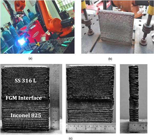
Figure 1. (a) - FGM wall fabrication process (b) Fabricated FGM wall (c) Dimensions of the FGM wall; (height, width, thickness).
Download figure:
Standard image High-resolution imageThe FGM wall is manufactured layer by layer transfer of molten metal with little heat input. To speed up cooling, aluminium fins and a blower are installed under the substrate holder. The FGM wall building process was fully automated and performed by a robotic CMT machine (Model: Fronius TPS 500i CMT), which builds the wall continuously without interruption, with no time between passes. In a fully automated robotic machine, the thickness of the wall to be built is taught using a teach pendant. This allows the robot to build the wall according to the predefined thickness. The CMT-WAAM deposition parameters are shown in table 2.
Table 2. CMT-WAAM deposition parameters employed in this research.
| Deposited material | Material feed rate (mm min−1) | Speed of Traverse (mm min−1) | Deposition current (A) | Voltage | Heat input (kJ mm−1) | Flow rate of argon gas (Lpm) | No. Of layers |
|---|---|---|---|---|---|---|---|
| Inconel 825 | 4700 | 145 | 150 | 15.2 | 0.943 | 10 | 20 |
| SS316L | 4000 | 145 | 110 | 11.5 | 0.523 | 10 | 20 |
Continuous and discontinuous cell dendrites make up the Inconel 825 part of the FGM wall. The SS316L is made up of delta ferrite in primary austenitic dendrites [45]. Pitting corrosion studies were performed as per ASTM G48-11 standard on the specimens extracted from Inconel 825, FGM interfaces and SS316Lwith dimensions of 40 mm×20 mm × 8 mm using wire cut EDM. All the extracted specimens were ground using 1200 grit silicon carbide paper and mirror polished with diamond paste using a cloth grinder before conducting the corrosion experiment. The test solution is 100 g of ferric chloride hexahydrate in 900 ml of distilled water. The specimens were immersed in the test solution for 24, 48, and 72 h. The experiment was conducted at a temperature of 50 °C. The specimen is then removed, rinsed with water, and scrubbed under running water with a nylon scrubbing brush. After that, the specimen is soaked in acetone or methanol and air-dried. The weight loss of the specimen is measured to an accuracy of 0.01 g. SEM and x-ray EDS were used to analyze the corrosion products at the corrosion pit.
3. Results and discussion
The microstructure of the as-deposited Inconel 825 specimen can be observed with an optical microscope (figure 2(a)). The micrograph depicts two distinct types of cellular-dendritic microstructures: continuous cellular-dendritic and discontinuous cellular-dendritic [46]. The optical micrograph (figure 2(b)) of the SS316L sample as it was deposited shows that delta-ferrite is present among the primary austenitic gamma-dendrites. An optical micrograph of the FGM interface zone, shown in figure 2(c), shows a microstructure transition from elongated to fine equiaxed dendrites with no defects such as cracks or delamination. Because the FGM interface is hypoeutectic, these fine equiaxed dendrites give outstanding corrosion resistance [47].

Figure 2. Optical micrographs (a) Inconel 825 specimen (b) SS316L specimen (c) FGM Interface.
Download figure:
Standard image High-resolution imageFigure 3 depicts the corroded specimens after 72 h in the test solution. The metallic lustre on the surfaces of the SS316L, Inconel 825 and FGM interface specimens faded after 24 h of exposure to the test solution. On the surface of SS316L, serious localised corrosion occurred and the corrosion started to grow when the exposure duration was increased to 48 h and subsequently to 72 h as shown in figure 3.
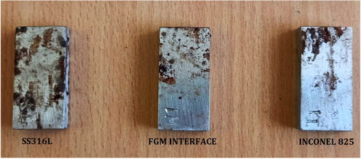
Figure 3. A photograph of the corroded samples after 72 h in the test solution.
Download figure:
Standard image High-resolution imageFigures 4(a)–(c) shows optical micrograph images and figures 4(d)–(f) shows the SEM images of SS316L after 24, 48, and 72 h of exposure to ferric chloride hexahydrate. The pits were approximated to be circular in shape, with a diameter of 30 μm after 24 h, increasing to 36 μm and 42 μm after 48 and 72 h, respectively. Figures 5(a)–(c) shows optical micrograph images and figures 5(d)–(f) shows the SEM images of FGM interface after 24, 48, and 72 h of exposure to the test solution. After a 24 h exposure period, the FGM interface surfaces were less corrosive and sustained their metallic lustre, with no pits found. Pitting commenced after 48 h of exposure and the pit measured 14 μm in diameter. After 72 h of exposure, the pit had expanded to a diameter of 18 μm. Figures 6(a)–(c) shows optical micrograph images and figures 6(d)–(f) shows the SEM images of Inconel 825 after 24, 48, and 72 h of exposure to the test solution. The Inconel 825 surfaces were less corrosive and maintained their metallic lustre after a 24 h exposure period, with no pits detected. Pits developed at the surface of the Inconel825 after 48 h of exposure with a pit diameter of 28 μm. When the duration was prolonged to 72 h, severe localised corrosion occurred expanding the pit diameter to 32 μm.

Figure 4. (a)–(c) Optical micrograph of SS316L after 24, 48, and 72 h (d)–(f) SEM images of SS316L after 24, 48, and 72 h.
Download figure:
Standard image High-resolution image
Figure 5. (a)–(c) Optical micrograph of FGM interface after 24, 48, and 72 h (d)–(f) SEM images of FGM interface after 24, 48, and 72 h.
Download figure:
Standard image High-resolution image
Figure 6. (a)–(c) Optical micrograph of Inconel 825 after 24, 48, and 72 h (d)–(f) SEM images of Inconel 825 after 24, 48, and 72 h.
Download figure:
Standard image High-resolution imageBoth the parent metals, SS316L and Inconel 825, showed spallation, which became more severe as the corrosive cycle progressed and the oxide scales spalled. It was also inferred that the spallation detected on the FGM interface was very little. The final weight loss after 72 h of exposure to the test solution was calculated to be 0.4620 g, 0.1087 g, and 0.1349 g for the SS316L, FGM interface, and Inconel 825 specimens, respectively.
The figure 7 shows the SEM/EDS line scan images of the corroded specimens extracted from the SS316L region, the interface region, and the Inconel 825 region of the fabricated FGM wall. The SEM reveals the morphology of the corroded surfaces and the EDS analysis show the elemental composition of the products of corrosion. As shown in the SEM micrograph/EDS image in the figure 7(a), the scales generated in the SS316L specimen are largely composed of the oxides of primary phases Fe, Cr, and small traces of Ni. The SEM micrograph/EDS image of the surface of the corroded FGM interface in the figure 7(b) indicates the formation of an oxide scale after 72 h of exposure. The major phases are Ni, Cr, and Fe. It is important to note that even after the corrosion cycle, most of the Ni remained available. The SEM/EDS image in the figure 7(c) shows the surface morphology of the corroded Inconel 825 specimen, indicating corrosion products (oxides) of Ni, Cr, and Fe as predominant phases, with small traces of Ti, Si, and Mn oxides.

Figure 7. SEM/EDS point scan analysis of the corroded specimens (a) SS316L (b)FGM interface (c) Inconel 825.
Download figure:
Standard image High-resolution image
The presence of protective scales rich in Ni and Cr phases at the FGM interface acts as a barrier to corrosion attack. Nickel is an austenitic stabiliser that helps the FGM interface resist corrosion. The second reason is because the FGM interface includes more silicon than the base metals. Because silicon is a 'ferrite' stabiliser, it improves corrosion resistance. It's most likely due to a refinement of the oxide grain structure and an increase in the oxide's adherence to the substrate, which prevents aggressive species like oxygen from corroding the austenitic FGM interface. At high temperatures, it could be the semi-conductive oxide layer itself, and the presence of the aggressive species - oxygen - is required for it to react with the FGM interface components - chromium, nickel, molybdenum, and possibly silicon - to form a high-temperature protective oxide. As a result, silicon improves the integrity of the self-generated diffusion barrier, which is most likely the reason for increase in pitting corrosion resistance. In addition, Silicon enhances active dissolution and contributes to the synthesis of hetero-poly acids with Molybdenum [47].
The EDS scan shows that a similar type of protective scale formed on the Inconel 825 specimen, which remained corrosion resistant to an extent, unlike the SS316L, which is comparatively less corrosion resistant where the corrosion products are rich in Fe. Higher concentrations of Fe2O3, which is considered vulnerable in nature, have been observed in SS316L, which could which could severely spall the oxide scale, resulting in the formation of pits. Spallation was found in the Inconel 825 specimen due to the presence of MoO3, which induces acidic fluxing in alloys. Moreover, this acid fluxing accounts for the formation of permeable oxides during corrosion. The FGM interface specimens' better resistance to pitting corrosion may be due to the increased NiO, Cr2O3, and slightly lower MoO3 contents.
4. Conclusions
It was found that the fabricated FGM wall was susceptible to pitting corrosion after varying exposure times. The findings are summarized as follows:
- 1.The final weight loss after 72 h of exposure to the test solution was calculated to be 0.4620 g, 0.1087 g, and 0.1349 g for the SS316L, FGM interface, and Inconel 825 specimens, respectively.
- 2.Higher concentrations of Fe2O3, which is considered vulnerable in nature, have been found in SS316L, which could cause the oxide scale to spall significantly, resulting in pit formation.
- 3.The higher NiO, Cr2O3, and slightly lower MoO3 concentration of the FGM interface specimens may reflect their improved resistance to pitting corrosion. Inconel 825 resists corrosion in test solutions to some extent and the spallation begins after 24 h. This was attributed to acidic fluxing caused by MoO3 that accounts for permeable oxide generation during corrosion, which contributes to the pit formation.
- 4.The order of the pitting corrosion resistance of the specimens extracted from the FGM wall was: FGM interface > Inconel 825 > SS316L.
According to the results of the corrosion studies, the FGM interface of Inconel 825-SS316L holds up well in pitting corrosion conditions.
Data availability statement
All data that support the findings of this study are included within the article (and any supplementary files).
Credit author statement
T S Senthil—Conceptualization, Data Curation, Investigation, Original drafting.
M Puviyarasan—Methodology, Visualization, Review & Editing, Supervision.
S Ramesh Babu—Validation, Analysis, Supervision.
T Ram Prabhu—Resources, Review & Editing.
5.: Declaration of competing Interest
The authors declare that they have no known competing financial interests or personal relationships that could have appeared to influence the work reported in this paper.