
Abstract
This study proposes and verifies bipolar electrostatic grippers stacking 3D-printed-layered modules consisting of arrays of elastically deformable bipolar beams. The influence of the mechanical compliance of grippers on the attractive force that it generates is clarified by comparing two types of modules having either high or low mechanical compliances. Experiments measured the attractive force of the gripper and demonstrated the pick-and-place performance of a thin film. The results show that mechanical compliance plays an important role in mitigating the attractive force decrease in stacking modules. The grippers' ability for thin film handling is demonstrated by observing pick-and-place behaviours of the proposed bipolar electrostatic grippers.
Export citation and abstract BibTeX RIS

Original content from this work may be used under the terms of the Creative Commons Attribution 4.0 licence. Any further distribution of this work must maintain attribution to the author(s) and the title of the work, journal citation and DOI.
1. Introduction
Electrostatic chucks (ESCs) are widely used for manipulations in various industries. The conventional ESC has a flat surface that is designed to handle flat target objects. One of the applications is in the semiconductor industry where an ESC is used to handle silicon wafers [1–5]. Recently, along with the increasing demand for wearable devices, there is a significant need for manipulating thin and flexible objects, such as dielectric films and Organic Light-Emitting Diodes (OLED) [6–9]. Among various manipulation methods [10–12], ESCs are getting attention because they can be used regardless of the operating environment. However, conventional ESCs are not designed to manipulate thin and flexible materials.
A beam-like compliant ESC structure consisting of elastic beams with bipolar electrodes has been proposed for this purpose. Such ESCs having a beam-array assembly can have advantages: (1) the ability to absorb surface-roughness and twisting of thin film-like materials by the mechanical compliance of the beams, and (2) the ability to detach target objects with a peeling motion enabled by a simple rotating mechanism [13]. There have been several attempts to develop bipolar ESCs in different ways. For example, a bipolar electrostatic chuck was created by stacking two monopolar electrostatic chucks, each having beam assemblies, by a wet etching process [14]. Integrated bipolar electrostatic chucks were created by the dry etching process of an integrated three-layer (conductor–insulator–conductor) structure [15] and additive manufacturing of conductive and nonconductive materials, namely 3D printers [13].
The bipolar electrostatic chuck with a beam-array assembly is designed based on the concept of realising a large area of the attractive surface by stacking (figure 1(a)). Previous research validated the concept of bipolar electrostatic chucks with surface flexibility by a collective elastically- deformable beam structure [13–15]. As a next step toward handling large films, it is necessary to increase the effective area of the attractive surface of the grippers. However, the influence of stacking on total attractive forces is not investigated. It was reported that the compliances of the bipolar ESC played a significant role in increasing the ability of the beam tip to change its shape by tracing the unevenness of target objects [13]. The mechanical compliance is also expected to have an important influence on the total attractive force of the stacked devices.
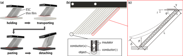
Figure 1. (a) Concept of handling, (b) module design and attractive force generation, (c) cantilever model of a beam.
Download figure:
Standard image High-resolution imageIn picking-and-placing manipulation, applied voltages are removed for detaching a thin film. Some attractive force remains due to residual charge at the tips [13]. While the residual charge has a small influence in a single module, a stacked device may get significant effects preventing the placing manipulation. A peeling motion was proposed to mitigate the influence of attractive force due to the residual charge [13]. However, the proposed trajectory has not been verified yet.
Therefore, this research aims to increase the area by stacking bipolar electrostatic attractive devices with a beam-array assembly and verifying the effect of beam compliance on its attractive force. We prototyped two types of 3D-printed bipolar ESCs having different mechanical compliances. The effect of stacking was verified by measuring and comparing the maximum attractive force per unit area of the individual bipolar ESCs and the stacked devices using the force-displacement curve.
This study also verified the trajectory of a peeling motion in detaching thin films. The stacked device was manipulated in two trajectories towards a thin film: vertical movement and peeling movement. The effectiveness of the peeling trajectory will be discussed by comparing demonstrations of both trajectories.
2. Device design and fabrication
2.1. Mechanical compliance of the chuck with a compliant beam-array assembly
To consider the mechanical compliance of the gripper, we focus on a single beam, as shown in figure 1(b). Here the beam is considered a cantilever beam of length L, whose root is fixed at angle φ measured from the horizontal line. The x, y, and z axes are set as shown in figure 1(c). The cantilever is assumed to be linearly elastic within relatively small deflection, and the axial stress can be negligible. The cantilever can be moved vertically along the z-axis by a displacement given to its tip. The reference position (z = 0) is defined at the point where the tip touches the object surface without any applied voltage.
The concentrated force, F, acting on the beam tip by the object is defined as positive upward, i.e., repulsive force. The attractive force is in the reverse direction. The relation between the curvature of the cantilever and a bending moment is given as equation (1), where EI is the flexural rigidity of the cantilever [13]. Equation (1) can be solved for the deflection of the cantilever at its tip, δ, which satisfies two boundary conditions: y(0) = 0 and y'(0) = 0. As a result, the deflection, δ, is obtained as equation (2). As the bending deflection of the cantilever is in the same direction as the given displacement, the relation between z and δ is expressed as  Due to the relation, equation (2) can be rewritten as equation (3).


Equation (3) shows that there is a linear relationship between force and displacement. The coefficient  represents the cantilever stiffness, namely the inverse of compliance. The coefficient suggests that it is effective for increasing attractive force to make modules have higher compliance. As derived from equation (2), to obtain more compliance, the length of the beam should be increased, and the height of the cross-section should be decreased.
In the actual electrostatic chuck, the force applied to the beam is considered as the electrostatic force  the elastic force of the beam
  and the normal force received from the surface
  The force acting on the target object can be given as the sum of these three forces. It means that the strategy for making it harder for the beam to leave the target is to make
  bigger and
  smaller, because the negative value of
  means the beam is not in contact with the target object. The value of
  can be increased by increasing the area of the electrode in contact with the attractive symmetry surface. The value of
  can be reduced by changing the beam's material and the cross-sectional second moment.
2.2. Design and fabrication of stacked compliant bipolar electrostatic chuck
By stacking five modules in layers , we synthesised a compliant bipolar electrostatic device having 3D-printed elastically deformable beams for handling a large film. We developed two types of bipolar electrostatic modules that have either low- or high-compliance beams. The design and dimensions of the two types of modules are shown in figure 2. The basic structure was similar to the previously developed structure for the 3D printing method [13]. The module had a four-layer structure with alternating layers of conductive and insulating layers. The outer insulation layer prevented the beams from contacting each other and energising when modules were stacked. The thickness of the conductive and outer insulating layers in the beam portion was 0.4 mm, and the thickness of the insulating layer sandwiched between the conductive layers was 0.8 mm. The modules were stacked on top of each other by passing M4 insulating screws through the 4.25 mm diameter holes in the modules. Insulation spacers and crimp terminals for voltage supply were placed between modules. This study stacked five modules, and the distance between modules was set to 2.4 mm. The appearance of the stacked modules is shown in figure 3.
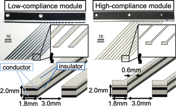
Figure 2. Schematic illustration of the two types of ESCs.
Download figure:
Standard image High-resolution image
Figure 3. Fabricated stacked high-compliance ESC device.
Download figure:
Standard image High-resolution imageA fused deposition modelling (FDM) 3D printer (Ultimaker3) was used to fabricate the modules. Carbon-mixed polylactic acid (PLA) resin (Proto-pasta PLA Conductive Black) was used for the conductor, and PLA (Ultimaker PLA Silver Metallic) was used for the insulator. The specifications of the 3D printer were as follows: nozzle diameter: 400 μm, minimum stacking pitch: 20 μm, positioning accuracy: 12.5 μm in the XY axis and 2.5 μm in the Z-axis.
The beam tips were flattened by pressing them against a slide glass (Matsunami Glass Ind., Ltd S1111) located on a hot plate (Azuwan HHP-411V) for increasing attractive force. The process follows the method that was developed by the previous study [13].
3. Experiment
3.1. Measurement of attractive force
The attractive forces of the developed prototypes were measured by an experimental setup, as shown in figure 4. The experiment setup consisted of a motorised stage (including stepping motor) connected to control vertical displacement, a precision balance (Sartorius QUINTIX224–1SJP, sensitivity is 0.1 mgf, required time for stability is 2s) to measure the attractive force between the device and a target object. The target object was three slide glasses (Matsunami Glass Ind., Ltd S1111, dimensions: 76 × 26 × 0.91, mass: 4.59 g) stacked and fixed with double-sided tape.
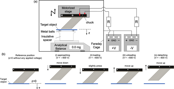
Figure 4. (a) Schematic illustration of the experimental system, (b) experimental procedure.
Download figure:
Standard image High-resolution imageThe device was pushed towards the target surface using a linear motion stage and then pulled up. The attractive force at each position was measured using the electronic balance. The slide glass was placed on small ceramic balls to allow the target object to move horizontally and stay fixed vertically, which eliminated the effect of horizontal force on the modules' beam tips. The average value of the three measurements was calculated.
The measurement procedure was as follows.
- 1.The beam tip was brought close to the slide glass, and the origin (Z = 0) was the position where the value of the electronic balance increased from 0 mg. The displacement Z was defined as positive in the direction of gravity.
- 2.The device's beam tip was pulled up to the position Z = −1 mm, and voltage was applied. The applied voltage was + 600 V for the positive electrode and −600 V for the negative electrode.
- 3.The stage was moved downward with a step displacement of 5 μm every 2.2 s until Z = 1 mm. The stage was stopped at Z = 1 for 10 s. The values of the electronic balance were measured throughout the manipulation.
- 4.The stage was moved until all beams detached from the target object: Z = −1 mm for the low compliance modules and Z = −3 mm for the high- compliance modules.
Since the surface areas of the beam tips differ depending on design, it is necessary to compare the forces per unit area. The gripping area of one device was defined as shown in figure 5. We calculated attractive force per unit area with the definitions. The value of the attractive force per unit area, P, was given as equation (4), where Am was the attractive area of one module, n was the number of modules stacked, and F was the measured attractive force.

Here Am was given with equation (5) using the dimensions given in figure 5. The various values of the devices used in this study and the values of Am calculated from equation (3) are summarised in table 1.

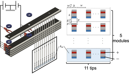
Figure 5. Schematics of the attractive area.
Download figure:
Standard image High-resolution imageTable 1. Specification of module design relevant to the attractive area.
| Device Type | Low compliance | High compliance |
|---|---|---|
| b [mm] | 1.2 | 1.8 |
| w [mm] | 3.6 | 3.0 |
| h [mm] | 1.6 | 1.6 |
| g [mm] | 2.4 | 2.4 |
| Am [mm2] | 211.2 | 211.2 |
3.2. Pick and place demonstration
A pick-and-place of a thin dielectric object was demonstrated to evaluate the performance of the prototyped stacked device. The same experimental setup as for the attractive force measurement was used, although the ceramic balls and the precision balance were excluded.
The target object was a polyimide film (DuPont Electronics, Kapton film: a rectangular shape of 20 mm × 55 mm × 12.5 μm, 22.4 mg). Since the residual charge on the electrodes of ESCs was expected to generate enough attractive force to hold the target object, a trajectory was proposed to detach the thin film. In this experiment, we compared two trajectories: a vertical trajectory and a peeling trajectory. The vertical trajectory gave vertical displacement alone while the peeling trajectory rotated the module and gave vertical displacement simultaneously. The target object was initially placed on tissue paper. Figure 6 depicts the experimental procedure, which is a sequence of four phases: (i) approaching, (ii) making contact, (iii) holding, and (iv) detaching.
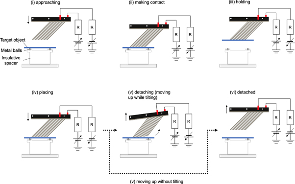
Figure 6. Experimental procedures for evaluating the pick-and-place performance of the prototype modules.
Download figure:
Standard image High-resolution imageAt phase (i), the prototype device was moved into contact with the target object while DC voltages of ±600 V were applied (figure 6-(i)). Once the device attracted the target object (figure 6-(ii)), the module picked up the object and held it by external displacement (figure 6-(iii)). At phase (iv) , the device was moved till the target object came in contact with the initial supporting object. The applied DC voltages were cut off and the module's electrodes were moved upward with two different trajectories. The peeling trajectory consisted of vertical displacements (5 μm every 2.2 s) and rotations (0.83 degrees per second), both of which were given simultaneously. A video camera was used to record the experimental results. The vertical trajectory only used vertical displacement at the same speed as the peeling trajectory.
4. Result and discussion
4.1. Effect of compliance on piling chuck
Figure 7 plots how the force generated between the prototype module and the slide glass changed according to the given displacement. The sequential numbering of the four phases of the experiment shown in figure 6 corresponds to those shown in figure 7. The black plus marks denote the result of a single module while the square markers denote the result of stacked modules.
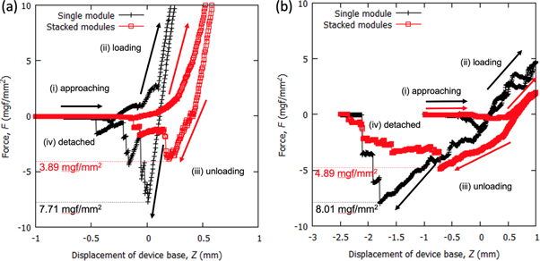
Figure 7. Displacement and force curve. (a) Low-compliance module, (b) high compliance module.
Download figure:
Standard image High-resolution imageIn both high- and low- compliance single modules, almost no force was observed at the beginning of the approaching phase. When the module came close to the target object yet before having reached the reference point, the attractive force was clearly measured as a negative force in figure 7. After the beam made contact with the target object, further displacement caused the module to be pressed against the target object (loading phase), which gave rise to a repulsive force. The linear relation was qualitatively consistent with the theoretical prediction given by equation (3).
When the module was pulled up (unloading phase), the repulsive force decreased linearly. Once the repulsive force became zero, the attractive force was observed. During this phase, the attractive force followed the linear path because the device would have been deforming to keep contact with the object. The attractive force continued to decrease, and lastly, at a limit of the deformation, the module detached from the object. Figure 7(b) shows the similar behaviour of the force-displacement curve for stacked modules. The degree of compliance can be evaluated by the degree of the gradient of linear increase during loading. Figure 7 shows that high- compliance modules had smaller gradients, which meant high- compliance modules had high mechanical compliance. The observed zigzag line reflects that beams touch and detach one at a time, which can be seen in the time-lapse pictures shown in figure 8.
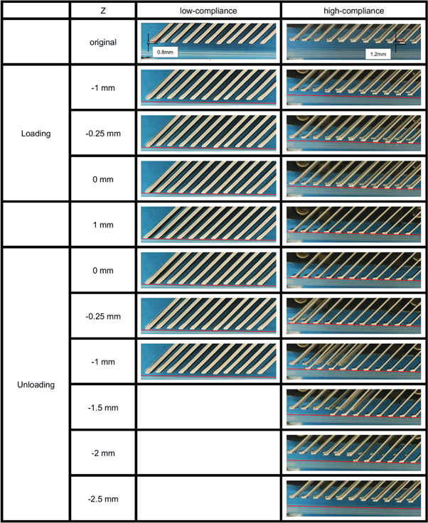
Figure 8. Time-lapse of beam tips (stacked low- compliance module and stacked high- compliance module).
Download figure:
Standard image High-resolution imageThe results showed both stacked devices decreased the attractive force per unit area from a single module. The reason behind the decrease was the beam tips of each module were not perfectly aligned to a flat surface as shown in figure 8. The misalignment was caused by fabrication accuracy which resulted in slightly different module shapes.
Table 2 shows that the reduction ratio of low-compliance modules was 49.5% while that of high-compliance was 39.0%. The high-compliance beams cancelled the gaps of the beam tips. From the behaviour of the beam tips, as shown in figure 7, it was confirmed that the beam of the high-compliance module negated a small gap by bending the beam when unloading.
Table 2. The maximum attractive force per unit area and attractive force reduction ratio due to stacking.
| Module type | Low-compliance | High-compliance |
|---|---|---|
| Single module (1 module) | 7.71 mgf mm−2 | 8.01 mgf mm−2 |
| Stacked device (5 modules) | 3.89 mgf mm−2 | 4.89 mgf mm−2 |
| Attractive force reduction ratio | 49.5% | 39.0% |
The results suggest two important factors to mitigate the decrease due to stacking. One was the lower degree of gaps of each beam tip between modules and within modules. The other was a high beam compliance that could cancel the gaps of the beam tips.
4.2. Pick and place demonstration
A rectangle polyimide film was pick-and-placed on the stacked high- compliance device. Figure 9 shows timelapse pictures of the handling experiments of both the vertical trajectory and peeling trajectory. The result shows that the residual force on the ESCs prevented the beam from detaching from the target film even when the applied voltage was 0 V. On the other hand, the detaching with the peeling trajectory enabled the beams to detach from the polyimide film and successfully leave the film on the target surface. The simultaneous vertical movement and rotation caused a peeling effect in the contact interface between the beam tips and objects. The result showed that the peeling trajectory is a successful strategy to cancel the attractive force due to the residual charge.

Figure 9. Time-lapse pictures of a stacked device handling a thin polyimide film.
Download figure:
Standard image High-resolution image
5. Conclusion
This study developed a large-area bipolar electrostatic chuck with compliant beam-array assembly by stacking modules fabricated by 3D printers and evaluated its performance by measuring the force-displacement curve. The result shows that by stacking the modules, the attractive force per unit area decreased due to the misalignment of the beam tips between the modules. It is also shown that solutions to the reduction are the mechanical compliance of the beams and the uniformity of the beam tip height in stacking. In addition, the stacked bipolar electrostatic devices successfully handled thin films by a peeling trajectory which gives vertical displacement and rotation to the device at the same time. These results indicate that the proposed stacked bipolar electrostatic device is a promising concept for handling thin films.
Acknowledgments
This work was supported by Grants-in-Aid for Scientific Research of the Ministry of Education, Culture, Sports, Science and Technology of Japan(16H04297, 20H02112).
Data availability statement
The data that support the findings of this study are available upon reasonable request from the authors.