
Abstract
Membrane emulsification is a promising new technique that can be deployed as a scalable modular conduit for the consistent and continuous production of single and complex emulsions. This work reports on the development of a manufacturing platform based on membrane emulsification for the first time for microcapsule-based self-healing cementitious materials. The feasibility of single and double emulsion production with wall formation as a secondary step through UV radical polymerisation was explored using a discrete membrane emulsification dispersion cell. The operational parameters (pressure, dispersed phase flux, temperature, shear rate) were established for the specific phase characteristics (viscosity, density, interfacial tension) to achieve control of emulsion droplets and maintain a high encapsulation of core content (high payload). Microcapsules with sodium silicate core and an average diameter of ∼130 μm were produced. Microcapsules were shown to achieve high payload (∼89%). Moreover their thermal stability was characterised and their release performance in the cementitious matrix established. The results demonstrated the capability of membrane emulsification to produce microcapsules with an aqueous core for use in self-healing of cementitious materials.
Export citation and abstract BibTeX RIS

Original content from this work may be used under the terms of the Creative Commons Attribution 4.0 licence. Any further distribution of this work must maintain attribution to the author(s) and the title of the work, journal citation and DOI.
1. Introduction
One of the most exciting and fledgling trends in material innovation that is set to revolutionise infrastructure are biomimetic and in particular self-healing materials [1, 2]. Self-healing materials are designed to repair their own damage, thus providing enhanced performance, safety and sustainability through reduced inspection, repair and disruption costs [3]. Recent advances have emerged with scientific breakthroughs in self-healing technologies for cementitious materials [4, 5]. Amongst these, engineered microparticles or microcapsules filled with repair agents, that can be added to the material during mixing show promise [6, 7]. As cracks begin to form, these release their content which in turn repairs the host matrix restoring partially or fully its properties.
To date, several microencapsulation techniques have been explored to deliver a range of repair materials and functionalities for self-healing concrete applications. Complex coacervation [8], in situ and interfacial polymerisation [9–14] or sol-gel reactions [15] have been proposed to incorporate silica-based sources, in cement-based composites. These types of cores are particularly desirable as they can readily react with the Ca(OH)2 in the hardened cementitious environment to form secondary calcium-silicate-hydrate gel [16]. However, encapsulation through traditional bulk emulsion approaches is hard to control and can lead to polydisperse systems [17]. The latter can not only affect the polymerisation/wall formation process but also further hinder equal dosing of the active ingredient in the formed microcapsules [18]. These limitations are compounded when considering bulk production. Significant effort has been dedicated into optimisation of the droplet breakdown procedures in terms of emulsification process scale-up. Within this remit production of emulsions using drop-by-drop approaches is of growing interest as it allows greater control over droplet size distribution and properties [19]. Such approaches include the use of flow focusing (microfluidic) devices or controlled pore-size membranes (membrane emulsification). The distinguishing features of the latter deviating from traditional technologies is that rather than continuously breaking down droplets to smaller sizes till the final required size is achieved, each droplet is produced individually with the final desired dimensions.
One step formation of droplets offers not only greater control over emulsion microstructural attributes allowing reliable consistent and repeatable creation of desired emulsion structures [20] but also the lower energy input results in fewer thermal and shear effects on those emulsion constituents [21]. Moreover these advantages over traditional breakdown methods allow modular and easy scale-up bespoke droplet formation with low energy and material consumption [21]. Here droplets are produced individually in a single step when the dispersed phase is pressed through a microporous membrane. Then droplets are formed on the other side of the membrane that is in contact with the continuous phase at the opening of each pore [21–23]. Once the droplets reach critical dimensions they detach into the continuous phase either due to spontaneous deformation driven by free-energy minimization or through shearing generated by a continuous phase flow over the membrane surface [22].
In recent years membrane emulsification has been explored as an advanced encapsulation platform with particle formation taking place as a second step through solidification of droplets. It has been used to produce a range of particulate systems including microcarrier microspheres such as chitosan gel beads [24, 25], alginate beads [26] and alginate chitosan beads [27, 28], polymers [29], inorganic oxides [30], carbon [31], metals [32], and solid lipids [33]. But also for generation of porous particles [34] and particles with core/shell morphology such microcapsules [28, 34–40]. However microencapsulation of aqueous cores produced by membrane emulsification has not yet been demonstrated using UV-initiated radical polymerisation. Moreover to the best knowledge of the authors membrane emulsification still remains unexplored for self-healing material applications.
Previous work has investigated other flow-focusing approaches to encapsulate self-healing agents in microcapsules with polymeric acrylate shells leading to advanced shell functionalities and performance [41, 42]. However microchannel emulsification due to low volume flow rate of the dispersed phase, has been primarily limited to smaller laboratory scale with production rates in the range of microliters per minute [43]. Being able to scale-up the production of very promising complex microparticles in a reasonable amount of time will allow the systematic investigation and development of superior material properties. This research aims to demonstrate the potential of membrane emulsification as an alternative production avenue of microcapsules with polymeric shells to encapsulate agents for self-healing action in cementitious materials. Herein we propose a novel protocol through membrane emulsification for production of uniform acrylate-shell microcapsules with diameters between 100 and 200 μm having a single liquid aqueous core using UV polymerisation for shell formation. The influence of operating parameters, presence of surfactant, and dispersed phase concentration on the formation of single and double emulsions were investigated in a Dispersion cell [44]. Finally the complex particles formed were characterised through optical and scanning electron microscopy, their thermal stability and chemical composition confirmed via thermogravimetric analyses and their compatibility, fracture behaviour and ability to deliver an active compound upon triggering assessed within a cementitious matrix.
2. Methods and materials
2.1. Materials
Trimethylolpropane ethoxylate triacrylate (TMPTA) and the photoinitiator hydroxy-2-methylpropiophenone (HMPPP) used to initiate the polymerisation of the acrylate were purchased from Sigma Aldrich, UK and formed the photocurable oil phase. Poly(vinyl alcohol) (PVA, MW 31000–50000, 98%–98.8% hydrolysed, ACROS Organics, Belgium), and SPAN 80 (Polysorbate 80, Sigma Aldrich, UK) were used as a surfactant to tune the interfacial tension and the viscosity of the aqueous phases. Sodium silicate solution (SS) purchased from Sigma-Aldrich (Na2O, ∼10.6% and SiO2, ∼26.5%) with deionised water was used as the core material. Fluorescein sodium salt (Sigma Aldrich, UK) was added in the core solution to aid observation and tracking of core retention of formed microcapsules. All chemicals were used without further purification (table 1).
Table 1. Density and viscosity of surfactant solutions used in this work.
| Density (kg m−3) | Viscosity (mPa·s) | ||
|---|---|---|---|
| AQUEOUS | Deionized water | 997.1 | 0.891 |
| 1 wt% PVA | 1005 | 1.11 | |
| 2 wt% PVA | 1007 | 2.31 | |
| 5 wt% PVA | 1015 | 7.35 | |
| 10 wt% PVA | 1028 | 18 | |
| Sodium silicate | 1390 | 60 | |
| OIL | TMPTA | 1110 | 50 |
| SPAN 80 | 986 | 1200 |
2.2. Experimental
2.2.1. Membrane emulsification with stirred cell
The ability to form simple emulsions was investigated as a droplet template for the later formation of complex microparticles. Oil-in-water (O/W) emulsions were obtained using a stirred cell (LDC-1) with a flat disc membrane under a paddle blade stirrer, as shown in figure 1. Both stirred cell and membrane were supplied by Micropore Technologies Ltd. The agitator was driven by a 24 V DC motor (INSTEK Model PR 3060) and paddle rotation speed in the range from 115–2672 rpm was controlled by the applied voltage. A hydrophilic stainless steel ring membrane with pores of dp = 100 μm and a pore spacing of L = 1100 μm was used.

Figure 1. Experimental setup of stirred cell used to produce single and double emulsions and steel ring membrane supplied by Micropore Technologies Ltd.
Download figure:
Standard image High-resolution imageTrimethylproprane ethoxylate triacrylate (TMPTA) was selected as wall forming acrylate and comprised the oil phase in all investigations. PVA surfactant was used as surfactant and viscosity modifier of the aqueous phases. Parameters were selected to generate formulations replicating processes from microfluidics [41, 42] and because the synthesized particles serve as an initial proof of concept of the manufacturing template. Our overall goal was to find a set of parameters with which a polydispersity as low as possible and an output rate as large as possible could be obtained.
Prior to emulsification, the membrane was pre-soaked in a wetting agent for at least 30 min to increase the hydrophilicity of the surface. The dispersed phase was injected through the membrane using a peristaltic pump (Watson-Marlow-Bredel Pump 101 U/R, Cornwall, UK). Flow rates of 1 ml min−1 and 5 ml min−1 were used corresponding to a dispersed phase flux ranging from 33.5 m3/m2h to 167.6 m3/m2h respectively. Stirrer speeds were set from 6 V to 12 V. The initial volume of continuous phase in the cell was maintained at 85 cm3 to allow for a constant 15% by wt dispersed phase concentration to be reached in the final emulsion. Once the desired amount of dispersed phase had passed through the membrane and the desired final concentration achieved, both the pump and the agitator were switched off and the droplets were collected and analysed. The cell was subsequently disassembled, and the membrane washed. The membrane washing procedure consisted of alternating immersion and treatment in 4 M NaOH in an ultrasonic bath for 1 min, rinsing and treating with deionized water followed by treatment in 2% citric acid solution for 1 min.
2.2.2. Generation of double emulsions and microencapsulation
To produce discrete core–shell microstructures (microcapsules) double emulsions were assessed. Herein the compound to be encapsulated (W1) formed the inner phase whereas the photocurable oil, the middle phase (O). A template aqueous core solution containing 10%PVA by weight was investigated initially. This was later replaced by sodium silicate solution as a proof of concept for the production of microcapsules for self-healing cement.
These primary emulsions (W1/O) of the aqueous core and wall forming oil were prepared using an Ultra Turrax T25 Basic rotor-stator homogeniser to ensure good mixing. A constant speed of agitation of 15000 rpm was employed. These were then injected through the membrane of the stirred cell to form water-in-oil-in-water ((W1/O)/W2) double emulsions. The fluids met at the pore openings of the membrane, forming droplets of the dispersed phase (containing the aqueous core within the oil wall material) suspended in the outer continuous phase. The single and double emulsions and primary emulsions' formulations together with operating parameters are given in table 2.
Table 2. Formulations and experimental conditions used for the primary (W/O) and double ((W/O)/W) emulsions prepared using stirred cell.
| Organic phase | Aqueous phase | Operating conditions | ||||||||||
|---|---|---|---|---|---|---|---|---|---|---|---|---|
| Type | Amount | Water | Surfactant | Content (wt%) | Flow rate (ml min−1) | Stirrer speed | Flux (m3/m2h) | |||||
| Acrylate oil | 15 ml | 85 ml | PVA | 1% | 1 | 6 V (∼779 rpm) | 33.5 | |||||
| Acrylate oil | 15 ml | 85 ml | PVA | 2.5% | 1 | 6 V (∼779 rpm) | 33.5 | |||||
| Acrylate oil | 15 ml | 85 ml | PVA | 5% | 1 | 6 V (∼779 rpm) | 33.5 | |||||
| Acrylate oil | 15 ml | 85 ml | PVA | 2.5% | 1 | 12 V (∼1241 rpm) | 167.6 | |||||
| Acrylate oil | 15 ml | 85 ml | PVA | 5% | 1 | 12 V (∼1241 rpm) | 167.6 | |||||
| Acrylate oil | 15 ml | 85 ml | PVA | 1% | 5 | 6 V (∼779 rpm) | 33.5 | |||||
| Acrylate oil | 15 ml | 85 ml | PVA | 2.5% | 5 | 6 V (∼779 rpm) | 33.5 | |||||
| Acrylate oil | 15 ml | 85 ml | PVA | 5% | 5 | 6 V (∼779 rpm) | 33.5 | |||||
| Aqueous phase W1 | Organic phase O | Operating conditions | Aqueous phase W2 | Operating conditions | ||||||||
| Core | Surfactant | Content (wt%) | Type | Amount | Surfactant | Content (wt%) | Homogenizer | Water | Surfactant | Content (wt%) | Flow rate (ml min−1)/Flux (m3/m2h) | Stirrer speed |
| Water 3.75 ml | PVA | 10% | Acrylate oil | 11.25 ml | — | — | 15000 rpm | 85 ml | PVA | 1% | 1/33.5 | 6 V (∼779 rpm) |
| (3 min) | ||||||||||||
| Water 3.75 ml | PVA | 10% | Acrylate oil | 11.25 ml | — | — | 15000 rpm | 85 ml | PVA | 2.5% | 1/33.5 | 6 V (∼779 rpm) |
| (3 min) | ||||||||||||
| Water 3.75 ml | PVA | 10% | Acrylate oil | 11.25 ml | — | — | 15000 rpm | 85 ml | PVA | 1% | 5/167.6 | 6 V (∼779 rpm) |
| (3 min) | ||||||||||||
| Water 3.75 ml | PVA | 10% | Acrylate oil | 11.25 ml | — | — | 15000 rpm | 85 ml | PVA | 2.5% | 5/167.6 | 6 V (∼779 rpm) |
| (3 min) | ||||||||||||
| Water 3.75 ml | PVA | 10% | Acrylate oil | 11.25 ml | SPAN80 | 2% | 15000 rpm | 85 ml | PVA | 1% | 1/33.5 | 6 V (∼779 rpm) |
| (3 min) | ||||||||||||
| SS+fluorescein 3.75 ml | — | — | Acrylate oil | 11.25 ml | — | — | 15000 rpm | 85 ml | PVA | 1% | 1/33.5 | 6 V (∼779 rpm) |
| (3 min) | ||||||||||||
To obtain solid microparticles, the liquid drops in emulsion were solidified through a second step free radical polymerisation of the photocurable oil phase initiated by UV irradiation. A UV-lamp Omnicure Series 1500 was used. Formed particles were then collected and washed for further characterisation and analyses.
2.3. Measurement of phase viscosity
The viscosity of the aqueous continuous phase was varied by addition and modification of the content of PVA stabiliser. The apparent viscosity was measured using a shear stress controlled rotational rheometer (Brookfield DV3T Rheometer) at a controlled shear-rate ramp. Samples with different PVA content were prepared and inserted into the rheometer sample cup and a subjected to a step-like shearing profile varying from 0 s−1 to 100 s−1+. The gradient of the linear regression of the shear stress versus shear rate was used then to obtain the viscosity.
2.4. Emulsion and particle size analysis
The visual microstructure appearance and droplet size distribution of the produced emulsions were analysed to gain insight into their microstructure stability using an optical microscope (DM 2700 M, Leica, Germany). The size distribution and diameter were calculated, by measuring the areas of the droplets with the software ImageJ (automatically or manually) on microphotographs. For each emulsion, three separate samples and measurements were performed and the mean average of these is reported. The relative span (coefficient of variation-CV) of the droplet distribution of the formed emulsions was used to express the degree of drop size uniformity according to [45, 46]:  where
where  the standard deviation and
  the mean average droplet diameter.
2.5. Modelling of droplet size
To provide further insight in droplet formation for the investigated formulations, a droplet size model introduced previously by [44, 47] was used. The droplet diameter (x) is calculated from force balance of the retaining (capillary force)) and detaching forces (drag force) acting on single droplet at a single membrane pore during the emulsification process as follows:

Where rp is the pore radius, τ is the shear stress, γ is the interfacial tension and x is the drop diameter.
The maximal shear over the whole membrane area is given by:

where rtrans is the transitional radius [47], η is the dynamic viscosity of continuous phase, ρ is the continuous phase density, ω is the angular velocity, and δ is the boundary layer thickness defined as

The maximum shear stress is then used in equation (1) to provide a prediction of the droplet size. The latter is compared with the experimental values obtained for different shear stress and continuous phase viscosity conditions investigated.
2.6. Thermal stability and microstructural characterisation
Scanning electron microscopy (SEM) using a Nova nanoSEM 450 under a 10 kV accelerating voltage was used to study particle shape, morphology and shell thickness of the solidified complex structures. Microcapsules were dried at room temperature and mounted on aluminium stubs. To measure shell thickness capsules were ruptured before imaging. Prior to SEM imaging, gold sputtering was performed on the samples.
Thermal stability of microcapsules was assessed by thermogravimetric analysis (TGA) using a PerkinElmer STA6000 Thermogravimetry/Differential Thermal Analyzer. The shell material was extracted by grinding the microcapsules and dissolving the aqueous core using water to separate it from the acrylate shell. The suspension was then filtered to obtain the shell debris which was dried in an oven at 50 °C to remove the moisture. A small quantity, ∼3–5 mg, of microcapsule samples and the shell materials was placed in a ceramic crucible and heated within the temperature range of 30 °C to 700 °C at a rate of 10 °C min−1 under air atmosphere.
2.7. Fracture behaviour of microcapsules in cementitious matrix-proof of concept
Formed microcapsules were added in a cement paste mixture (CEMI52.5N) with a water/cement ratio of 0.5 at a concentration of 5% with respect to cement weight. The microcapsules were added as a dry powder and were first mixed with the cement to obtain a homogenous dry mixture before the addition of the mixing water. The cement paste was poured into prismatic moulds (10 × 10 × 100 mm). The specimens were demolded after 24 h and subjected to water curing for 3 days. Subsequently cement samples were fractured by hand, and smaller segments of the fracture surface were extracted using a scalpel and dried for SEM observation.
3. Results and discussion
3.1. Feasibility of single emulsions
The dispersion cell was first used to generate stable single O/W emulsions of TMPTA in water that upon polymerisation could form solid microparticles. Here, we investigated the influence of the surfactant content, viscosity of continuous phase, dispersed phase flux and agitation speed on the emulsion characteristics and particulate formation.
3.1.1. Effect of continuous phase viscosity
The viscosities of the two emulsion phases individually as well as the ratio of dispersed phase over continuous phase can significantly influence the stability of the droplet formed. Herein we maintained the viscosity of the dispersed phase but modified the viscosity of the continuous phase. The effect of viscosity of the continuous phase was considered by modifying the content of PVA stabiliser. Three different contents were assessed (5%/2.5%/1%) by weight of solution. To control the process parameters and minimize the variables a constant injection rate of 1 ml min−1 and shear rotation equivalent to 6 V were selected. Results of the size distribution of the formed emulsions and corresponding microparticles are shown in figure 2 (left) and (right) respectively. Microparticles were obtained by crosslinking the photocurable oil phase in the single emulsion droplets in the collection vessel. It was found that decreasing the PVA content led to an increase of the droplet size improving size distribution.

Figure 2. (left) The droplet size distributions (given are the mean diameters) obtained by emulsifying an ETMPTA acrylate solution via the dispersion cell LDC-1 with a membrane pore diameter of 100 μm, an injection rate of 1 ml min−1, constant stirring voltage (6 V) for different surfactant contents (1%, 2.5% and 5% PVA). The corresponding photomicrographs of the emulsion droplets and formed polymerised solid particles with mean average size and the polydispersity index (right).
Download figure:
Standard image High-resolution imageResults for the 5% PVA content seem to further imply that although particle formation is successful with well-defined smooth spherical forms generated, some structures appear fused together (figure 2(f)). Thus 5% PVA was defined as the upper limit to be considered in the investigation of formulation parameters. Similarly, a critical (lower) content of PVA stabilizer by wt% of the solution in the continuous phase was identified below which the stability of the emulsion during polymerisation may be compromised. A closer view of the microstructure of the formed particles under SEM is shown in figures 3(a)–(b) and (c)–(d) for 5 wt% and 1 wt% PVA content respectively, confirming an upper and lower limit in the surfactant content and its effect on the particle formation stage.

Figure 3. (left) Particle solidification under UV irradiation post emulsification under microscope and corresponding SEM image (right) of particle microstructure. (a)–(b) Agglomerated droplets and fused structures are observed when a high emulsifier content was adopted whereas (c)–(d) Elongated structures and uneven shapes were observed when emulsifier content was too low (1 wt% PVA) to stabilise the final emulsion.
Download figure:
Standard image High-resolution image3.1.2. Effect of stirrer speed
A parameter influencing the droplet size and thus particle size distribution is the stirrer speed. In the case of stirred cell membrane emulsification, the detachment of the droplets from the surface of the membrane is facilitated by the shearing stress created by the stirrer. In turn the speed of rotation is controlled by the voltage applied to the stirrer. Herein we considered two different speeds of agitation 779 rpm and 1241 rpm corresponding to a stirrer voltage of 6 V and 12 V respectively [48]. Figure 4 (left) shows size distributions that were obtained when the stirrer speed was varied between 6 V and 12 V for membrane pore diameter 100 μm and a dispersed phase flux of 33.5 m3/m2h and the corresponding images of formed microparticles. When the agitation speed is systematically increased the droplets become increasingly smaller. This is consistent and independent of the viscosity of the continuous phase. Yet as the stirrer speed increases droplets become less polydisperse. Similar behaviour can be observed in membrane emulsification with stirred cell as well as other devices [45, 47, 49–52]. At 6 V the droplet diameters are ∼2 times larger than the membrane pore size compared to higher speeds of agitation where evidence of drop breakup can be seen with droplets smaller than the pore opening forming. Thus a careful balance of shear forces needs to be achieved [44].
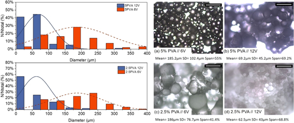
Figure 4. (left) Effect of speed of stirring on droplet size distributions obtained by emulsifying an ETMPTA acrylate solution via the dispersion cell LDC-1 for different surfactant contents (2.5% and 5% wt. PVA). (right) The corresponding photomicrographs of formed polymerised solid particles produced for (a)–(b) 5%wt PVA and (c)–(d) 2.5%wt PVA with varying speed of agitation. Scale 500 μm.
Download figure:
Standard image High-resolution imageThe model described in equation (1) is included in figure 5 for varying continuous phase viscosities. The model seems to reasonably fit the data taking into account the variation in continuous phase viscosity. Overall the mean droplet size reduces with increasing the applied shearing stress. However the uniformity is dependent on the viscosity of the continuous phase and the illustrated data seem to suggest that increasing the viscosity had a negligible effect on improving the degree of monodispersity of the emulsion.
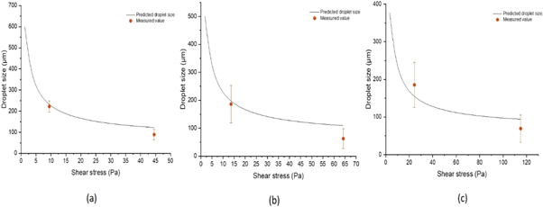
Figure 5. Comparison of mean droplet diameter and standard deviation of O/W emulsions as a function of shear stress for continuous phase viscosity of (a) 1%wt PVA, (b) 2.5%wt PVA and (c) 5%wt PVA respectively with predicted sizes from equation (1).
Download figure:
Standard image High-resolution image3.1.3. Effect of dispersed phase flux
The shear capillary model does not take into account the dispersed phase flux rather considers an almost zero flux rate providing a theoretical estimation of the droplet size [24]. However the dispersed phase flux can also affect the mean droplet diameter [49]. Herein we also considered the influence of the injection rate and thus the dispersed phase flux on the mean droplet diameter. Two different injection rates were considered 1 ml min−1 and 5 ml min−1 corresponding to equivalent 33.5 m3/m2h and 167.6 m3/m2h respectively. Figure 6 shows the development of mean droplet diameter and dispersity as a function of the dispersed phase injection rate for varying viscosity of the continuous phase, 5% PVA (top), 2.5% PVA (middle) and 1% PVA (bottom). A constant agitation speed of 6 V was used for the production of these samples. An increased injection rate is expected to lead to larger droplets as more liquid is pumped through the membrane per unit of time [44, 45, 50, 53]. This is indeed the case for emulsion produced with highest viscosity of continuous phase. However for lower viscosities the trend is inverted and an increase in dispersed phase flux from 33.5 m3/m2h to 167.6 m3/m2h led to a decrease of droplet size, from 221.9 μm to 85.04 μm for 1%PVA and 196.4 μm to 96.4 μm for 2.5% PVA content respectively. At highest flux rates a similar increased chance of instability and droplet breakup has been observed previously by [44]. This suggests that critical flux rate has been exceeded for our formulation and droplet formation at one single pore is affected by droplets at adjacent pores on the membrane surface. The latter has been described as a 'push-to-detach' mechanism with droplets detaching sooner producing smaller diameters [54].

Figure 6. Effect of injection rate on droplet size distributions and polydispersity for different surfactant contents (a) 5%wt PVA, (b) 2.5%wt PVA and (c) 1%wt PVA respectively.
Download figure:
Standard image High-resolution image3.2. Feasibility of double emulsions and microcapsule formation
The proposed discrete cell platform was also investigated to produce core–shell structures. That was made possible by the production of complex emulsions (W1/O)/W2 whereupon the middle phase (O) formed upon final polymerisation the wall/shell of the structure incorporating as core the inner phase (W1). W/O/W emulsions were generated using a two-part emulsification process. The first emulsion or preliminary emulsion W1/O comprised of a model aqueous phase in an oil acrylate TMPTA wall forming solution. The emulsion was formed by mixing the water core (10% PVA by weight of solution) in the TMPTA and photoinitiator solution to create a 25% by weight final emulsion in a homogenizer which was then converted into double emulsions ((W1/O)/W2) using membrane emulsification. Fluorescein dye (0.3 gr) was added in the inner phase to help observation of formed complex structures. We tried to transfer the results from the initial single emulsion scouting systems to ensure the formation of stable double emulsions. Thus the two lowest contents of PVA were considered to control the viscosity of the outer water phase.
Figure 7 shows size distributions of the droplets of the formed double emulsions with indicative photomicrographs of the complex droplets. Overall the dispersity of the formed emulsions is higher than the equivalent single emulsion formulations; . Reported size distributions for double emulsions produced with varying viscosity of the outer phase are in agreement with previous observations for single emulsions. Namely an increase in the viscosity led to a decrease in particle size, although the reported effect is less pronounced. For further comparison the dispersed phase flux was varied during emulsification to identify any effects on particle characteristics. It is possible here to discern the effect of an increase of the flux on the droplet size distribution. An increase from 1 ml min−1 to 5 ml min−1, (equivalent to flux increase from 33.5 m3/m2h to 167.6 m3/m2h) led to a twofold increase of the dispersity (figure 7 left) with evident droplet breakdown; namely from span = 12% to 45% and 26.5% to 47.1% for 1%wt PVA and 2.5%wt PVA content respectively.
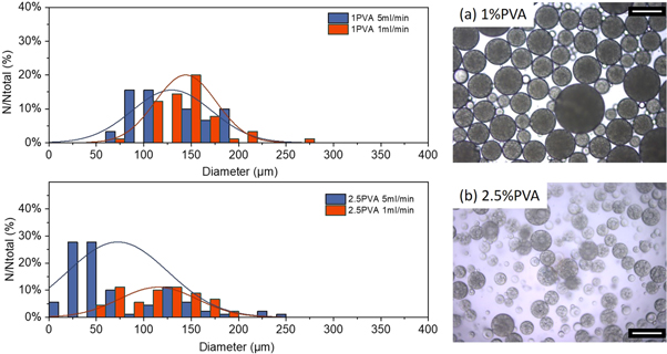
Figure 7. Effect of injection rate on droplet size distributions and polydispersity for different surfactant contents (a) 1%wt PVA and (b) 2.5%wt PVA (left) and indicative micrographs of formed double emulsions (right). Scale 200 μm.
Download figure:
Standard image High-resolution imageMoreover, it is interesting to assess the effect of flux on the polymerised particle characteristics. Initial assessment of wall thickness of formed microcapsules as shown in figure 8, identified a significant effect of the dispersed phase flux on the microcapsule wall formation. Lower flow seems to favour uniform thinner walls than when a higher flux is adopted. Concurrently flux is related to the concentration of the final emulsion, thus a higher flux yields a more concentrated, denser emulsion. The latter may also be interfering with UV light dispersion in the collection medium affecting uniformity of polymerisation. Thus, the lower flux was selected in further investigation to allows a more uniform and better controlled solidification of the shell during the polymerisation step. Concurrently the lowest PVA content was selected as an increase in viscosity of the continuous phase had negligible effects on the overall stability and uniformity of the produced double emulsions.

Figure 8. Effect of dispersed phase flux on core–shell morphology and shell wall uniformity. Micrographs of microcapsules produced with (a) higher injection rate 5 ml min−1 compared to (b) lower injection rate. Scale 100 μm.
Download figure:
Standard image High-resolution imageThe effect of emulsifier in the oil phase was also considered. A supplementary surfactant SPAN80 (2% by weight) was used in the middle O phase. A reduction in interfacial tension is expected to facilitate an early detachment from membrane, producing smaller droplets [55, 56]. This was confirmed in figure 9. The micrographs showed that the addition of SPAN80 led to smaller size double emulsion droplets with no evident improvement in the polydispersity of the emulsion. Further insight in the microstructural characteristics of the formed microcapsules was given by SEM imaging (figure 10). SEM imaging identifies increased porosity and incompletely formed wall structures when SPAN80 was used. On the other hand, PVA allowed for complete wall formation yielding smooth spherical microcapsules. As the presence of SPAN80 had a negligible effect on the size distribution and further negatively affected the wall formation subsequent formulations only considered surfactant in the aqueous phases (inner and outer).
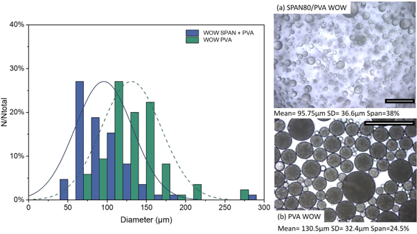
Figure 9. (left) The droplet size distributions (given are the mean diameters) obtained by emulsifying a preliminary (W1/O) to produce a (W1/O)/W2 with an injection rate of 1 ml min−1 and constant stirring voltage (6 V). The effect of surfactant in (a) both the dispersed and continuous phase and the (b) dispersed phase only were considered. The corresponding photomicrographs of the emulsion droplets and formed polymerised core–shell microcapsules with mean average size and the polydispersity index (right). Scale 500 μm.
Download figure:
Standard image High-resolution image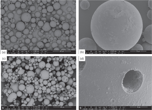
Figure 10. SEM images of core–shell structures produced (a)–(b) without and with (c)–(d) the addition of surfactant in the inner oil phase (W1/O)/W2 of the double emulsion. Increased porosity can be seen on the shell of particles formed with SPAN80.
Download figure:
Standard image High-resolution image3.3. Sodium silicate microcapsules
Based on our preliminary investigations for single and double emulsions a stable system is proposed for the production of microcapsules using a two step emulsification process. Sodium silicate was chosen as the prospective healing agent to replace the template aqueous solution as the inner phase. Fluorescein dye (0.3 gr) was added in the inner phase to help observation of formed microcapsules. These formed the primary emulsion produced through homogenisation (at 15000 rpm) and where subsequently dispersed through the stirred cell membrane setup. A constant injection rate of 1 ml min−1 and 6 V stirrer voltage was selected. A continuous phase of 1% PVA by weight aqueous solution was selected as the outer phase. A comprehensive overview of the fabrication process can be seen in figure 11. After the polymerisation of the photocurable oil, optical microscope (figure 12) and SEM images revealed clear-core–shell structure containing the liquid sodium silicate core within (figure 13). Microcapsules with average diameter of 130.8 μm and average shell thickness of 2.8 μm (±0.33 μm) were produced. Taking into account these dimensions, each microcapsule has 1.01 nl of core material and 0.14 nl of shell. If we consider the approximate density of the bulk shell material as 1.11 g ml−1 and the density of the core is 1.39 g ml−1, the core content is 1401 ng and the shell material is 158 ng. Thus, the shell represents ∼10% wt whilst the core ∼89% wt of the total material respectively.

Figure 11. Flow chart of the processes involved in the production of acrylate shell microcapsules enveloping sodium silicate through membrane emulsification.
Download figure:
Standard image High-resolution image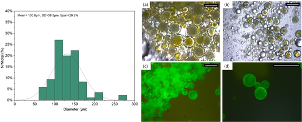
Figure 12. (left) The droplet size distributions (given are the mean diameters) with mean average size and polydispersity index of SS core- acrylate shell microcapsules produced via the dispersion cell LDC-1 with a membrane pore diameter of 100 μm, an injection rate of 1 ml min−1 and constant stirring voltage (6 V). (right) The corresponding photomicrographs of the (a) emulsion droplets and (b) formed polymerised solid particles and (c)–(d) microcapsules fluorescing under UV light. Scale 200 μm.
Download figure:
Standard image High-resolution image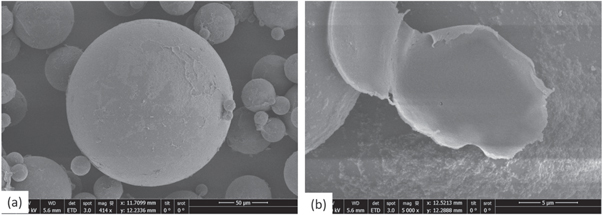
Figure 13. SEM images of dried and ruptured microcapsules.
Download figure:
Standard image High-resolution imageIn order to evaluate the chemical composition and thermal stability of the produced microcapsules, TGA analysis of the samples was conducted. The thermal stability of the microcapsules is important as it is desirable that the microcapsules maintain their stability over a wider range of relevant to concrete processing temperatures. Moreover thermal analysis can assist in the identification of the difference groups present in the shell and core material and provide further insight in the synthetic process and core content and retention. Figure 14 shows the TGA dotted curves corresponding to the shell material whereas the continuous line corresponds to the formed microcapsules with sodium silicate core. The curves for the bulk/shell material are similar up to 300 °C. This confirms the uniformity of the synthetic process of the acrylate shell and the successful production of acrylate shell microcapsules with sodium silicate core. The shell remains stable below 200 °C with main weight loss taking place between 200 °C and 550 °C due to oxidation of the shell. The curves for the microcapsules on the other hand differ. SS microcapsules show a loss below 200 °C signifying the dehydration of the SS confirming the successful retention of the SS as core material. Subsequent thermal degradation is attributed to the decomposition of PVA that may have been trapped in the core, confirming similar findings by [42, 57]. The comparison between shell and microcapsule is used to further confirm the core content. By comparing the TGA of the microcapsules and the shell material at 200 °C when the majority of mass loss can be attributed to the core material dehydration, the content of shell material was calculated to be 12.8% by total weight of microcapsules; thus the mass balance of 87.2% was attributed to sodium silicate as core. These values are in agreement with our initial theoretical estimation of mass fraction of core and shell components.

Figure 14. TGA curves of dried SS microcapsules compared to the bulk shell material and extracted microcapsule shell material.
Download figure:
Standard image High-resolution imageThe compatibility of the formed microcapsules and triggering mechanism under mechanical damage were assessed within the cementitious paste. To prove further that the microcapsules survived mixing and were dispersed well within the matrix, chips were extracted and viewed with the optical microscope (figure 15). Both brightfield and UV observations of the fractured surfaces identified the presence of dispersed intact capsules, ensuring that microcapsules had survived the mixing process. To further investigate the fracture mechanism SEM analysis was performed on the fracture surface of the prism specimens. The SEM images presented in figure 15, show many fractured microcapsules embedded in the cement paste matrix with dome-shaped cavities visible throughout the fractured surface of the specimens. Figures 16(b)–(c) shows the details of a fractured microcapsule embedded in the matrix. Wall thickness measurements confirm previous SEM observations of the morphology of the formed microcapsules with thin walls.

Figure 15. Microscopic images from crack plane: (a) brightfield image of the crack plane and (b) microcapsules fluorescing under UV light. Scale 500 μm.
Download figure:
Standard image High-resolution image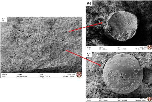
Figure 16. (a) SEM image of fractured surface of the prism-shaped specimens. Integration of microcapsules with sodium silicate core in the cementitious matrix, evidence of ruptured capsules (a) and unbroken/debonded (b) microcapsules can be seen.
Download figure:
Standard image High-resolution image
Microcapsules appear to have successfully fractured implying that sufficient interfacial bond strength between the shell of microcapsules and matrix has developed. Yet some remain intact with some evidence of debonding visible. Modification of the acrylate shell has been suggested previously to improve the chemical compatibility of the shell with the matrix [41]. It could be considered in further research to improve the bonding between the produced microcapsules and the matrix. Overall the observed fracture behaviour promotes the release of healing agents of microcapsules.
4. Conclusions
For the first time, membrane emulsification was used to produce microcapsules as delivery systems for self-healing in cementitious materials. A microencapsulation template for aqueous healing agent using UV-radical polymerisation was proposed which if run in a continuous process will allow high output rates. The feasibility of simple and double emulsions using water as model core and acrylate oil was assessed though a stirred cell membrane setup and the influence of membrane operating parameters, presence of surfactant, and dispersed phase concentration on the properties of the formed emulsions were investigated.
After preliminary feasibility investigations, the template was adapted for the microencapsulation of sodium silicate. Sodium silicate core microcapsules with a mean diameter of ∼130 μm and high core loading (89%) were obtained. Thermogravimetric tests confirmed the chemical termination and successful synthesis of the acrylate shell and encapsulation of the aqueous core. Proof of concept investigation was completed to validate both their survivability within the matrix as well as their fracture behaviour in situ. To sum up, the manufacturing platform and formulation outlined herein can be further extended to encapsulate a range of aqueous healing agents opening up new opportunities for further advancing smart materials.
Acknowledgments
Financial support from the UK Engineering and Physical Sciences Research Council (EPSRC) Resilient Materials for Life (RM4L) Programme grant (EP/P02081X/1) is gratefully acknowledged.
Data availability statement
All data that support the findings of this study are included within the article (and any supplementary files).
CRediT authorship contribution statement
Chrysoula Litina: Conceptualization, Methodology, Software, Formal analysis, Investigation, Resources, Data curation, Writing—original draft, Writing—review & editing, Visualization. David Palmer: Validation, Writing—review & editing. Abir Al-Tabbaa: Conceptualization, Validation, Writing—review & editing, Supervision, Project administration, Funding acquisition.
Declaration of competing interest
The authors declare that they have no known competing financial interests or personal relationships that could have appeared to influence the work reported in this paper.