
Abstract
A variety of applications, spanning from structural or biomedical engineering to flexible electronics, require the development of materials able to withstand high load and, at the same time, accommodate high strain before failure. While strength and toughness are often self-excluding properties in man-made materials, they can be efficiently combined by nature, which provides source of inspiration for novel materials design. Herein this paper, we pursue a bio-inspired approach, based on the introduction of a mechanical sink, such as a running knot, to improve the toughness modulus of high-performance polymeric microfibres. These are then enriched with additional smart features, such as a viscoelastic coating, surface roughening or a combination of those, to amplify the beneficial effect of the knot introduction. The role played by all such features on the mechanical performances of the prepared fibre samples, namely load at failure and toughness modulus increase, is then evaluated through a statistical technique, known as correspondence analysis (CA). While this exploratory analysis is widely adopted in biology, ecology, neuroscience or genetics, applications in structural or mechanical engineering are still rare. Here, we show that CA can be a powerful tool for the design of materials provided with enhanced toughness without losing strength.
Export citation and abstract BibTeX RIS
Introduction
Traditional engineering materials are usually capable of either accommodating high strain or sustaining high loads and thus, for centuries, strength and toughness were considered self-excluding mechanical properties of man-made materials [1]. The availability of materials that can combine both such properties has been intensively sought in several fields, ranging from structural [2] or biomedical [3] engineering to the emerging fields of soft robotics [4] or flexible electronics [5], where they could also enable the development of new device concepts. Materials' toughness can be improved by developing functional mechanisms capable of deviating, bridging or trapping the front of a crack [6, 7], thus preventing its uncontrolled propagation and a following catastrophic failure. This condition can be achieved in several ways; for example, through the incorporation of fillers dispersed in a matrix according to specific designs. In many cases, these follow a bio-inspired approach [8] and aim at reproducing complex, multiscale and hierarchical architectures that characterize naturally tough and strong materials, such as nacre [9, 10], bones [11] or bamboo. In addition to the study of specific materials' composition and internal patterns, toughness of materials, especially 1D materials, such as microfibers, can be improved by a more mechanical approach, based on the introduction of a sacrificial structural element, as proposed in [12]. Similar to the rupture of sacrificial bonds in protein-based materials, such as spider silk, a properly designed sacrificial structure causes, upon the application of an external load, the unravelling of a hidden length, which is accompanied by an even significant release of energy, which sums up to the energy dissipated by the microfiber in normal condition, under loading, with a consequent increase of its toughness modulus [13]. The amount of the achievable toughness enhancement strongly depends on the design of the sacrificial structure, which can take the shape of intriguing topological, smart elements, such as loops or knots [14], as reported in past [15–17] and more recent [18, 19] studies.
In this paper, to improve the toughness modulus of high-performance polymeric fibres, a slip or running knot in the shape of a noose was introduced as a sacrificial element. During a tensile test, the knotted fibre can slide within the knot, which gradually loosens until its complete unravelling. Such mechanism does not compromise the fibre's load bearing capability, as no stress concentration points are basically generated, yet additional energy is dissipated by friction. In order to maximize the friction contribution, which is limited by the surface smoothness of these fibres, we coupled the knot with additional features, such as a viscoelastic coating or surface roughening. The effectiveness of the considered strategy to enhance the fibres' toughness modulus not at the expense of the strength was evaluated through a statistical approach based on the correspondence analysis (CA). This is an exploratory technique used in a wide range of fields, from biology [20] or ecology [21] to neuroscience [22], genetics [23] or marketing [24], to study common properties featured by data groups (either numerical or categorical) and to identify the most influential parameters on specific variables [25]. In contrast to other multivariate methods, as the principal component analysis (PCA) [26], CA does not imply the adoption of specific analytical models to express relationships among variables mediated by coefficients, whose values require an initial guess. In addition, CA can describe correlations not only within a single group of data but also across two different groups, at the same time. In the following, we apply the CA to find correlations between different fibre sample preparations and observed mechanical performances.
Materials and methods
Samples preparation and mechanical testing
The polymeric microfibres considered in this study are 'Spectra 2400' polyethylene fibres by Honeywell International Inc. These are characterized by a diameter of 33 μm, a linear density equal to 0.915 g/mm, strength of 2636 ± 448 MPa and strain at failure of 28 % ± 16% mm/mm. Some of the fibres were coated with a 2.5 μm thick viscoelastic layer made of commercial silicone. This coating resulted from the immersion of the fibre in a silicone bath, followed by a rapid release and then overnight drying. Some of the fibres were tested as control samples, with 10 mm gauge length, while others were provided with a hand-made running knot (i.e., noose), with a distance between the fibre ends (end-to-end fibre length, l0) of 10 mm and an initial total length (l) of 20 mm (accounting for both l0 and the fibre length involved in the knot). Knots were introduced in the fibres through manual manipulation assisted by tweezers and the final knot loop length was measured with a callipers after tightening the knot as much as possible. In addition, the surface of some of the coated fibres was roughened by a sand paper, before tying the knot, in order to increase the energy dissipated by friction during the knot unravelling. Finally, in some samples a localized silicone droplet was deposited to cover the knot surface. Fibres with the silicone droplet were left to dry overnight before testing. All the prepared samples were mounted on a square paper frame, which provided samples with a gauge length equal to 10 mm. The fibres were fixed to the sample holder with a commercial rapid glue. An overview of the prepared fibre samples is reported in figure 1 and table 1. After preparation, the fibres were loaded with a uniaxial force by electromechanical testing machine MIDI10 by Messphysik Materials Testing, with a strain rate of 0.5%/s. Each sample was subjected to one complete cycle of loading, until the release of the knot and final failure of the fibre.

Figure 1. (a) Sample 0—As-produced fibre. (b) Sample C—Fibre covered with a viscoelastic coating. (c) Fibre with a rough viscoelastic coating. (d) Sample N—As-produced fibre with a noose. (e) Sample CN—Fibre with a viscoelastic coating and a noose. (f) Details of sample N. (g) Details of sample ND—As-produced fibre with a noose and a concentrated drop of silicone on it. (h) Details of sample CN. (i) Details of sample CNR—Fibre with a rough viscoelastic coating and a noose. (l) Details of sample CNRD—Fibre with a rough viscoelastic coating, a noose and a concentrated drop of silicone on it. Scale bar: 200 μm.
Download figure:
Standard image High-resolution imageTable 1. Description of the prepared samples.
| Sample Acronym | Description | Number of tests |
|---|---|---|
| 0 | -As-produced fibres | 9 |
| C | Fibres covered with a viscoelastic coating | 4 |
| N | As-produced fibres with a noose | 4 |
| ND | As-produced fibres with a noose and a concentrated drop of silicone on it | 7 |
| CN | Fibres with a viscoelastic coating and a noose | 5 |
| CNR | Fibres with a rough viscoelastic coating and a noose | 6 |
| CNRD | Fibres with a rough viscoelastic coating, a noose and a concentrated drop of silicone on it | 7 |
Correspondence analysis
Since a knot, a viscoelastic coating, surface roughness or a combination of those are categorical variables, also the variables P or % T were subdivided into categories. A contingency matrix was compiled for either the load at failure, P, or the percentage enhancement of toughness modulus, % T; either matrix includes I rows (i.e., category of tested fibre, where each category corresponds to the presence of specific features in the fibre, such as presence of knot or coating or surface roughness or a combination of those) and J columns (each corresponding to a categorical value of P or % T, as obtained from the tensile tests). Each element of the contingency matrix reports the number of tests performed on a given fibre category whose load at failure or toughness modulus enhancement falls within a specific interval. The CA was implemented through Past 4.02 free software and provided a bi-dimensional plot, where all the rows and columns are converted into points, whose first two or three coordinates allow to identify possible similarities. In order to perform our analysis, we computed (i) the profile of each row ri , which was derived by normalizing each element with respect to the marginal total ni (i.e., sum of all the elements within a row); (ii) the mass wi of a row, which was obtained from ni divided by the sum of the total of each row (overall total, n). The graphical representation obtained from the CA is a cloud of points (with coordinates fi,1, fi,2) representing all the row profiles in a Euclidean space, where the centre (i.e., axes origin) corresponds to an average profile. The more two points (i.e., row profiles) are close to each other, the higher the similarity between them. The sum of chi-squared distances of each point (weighted by its mass) from the centre is called inertia λ; this is a measure of how much the individual profiles are spread around the centre. The same considerations could be repeated for the columns, thus obtaining a second plot with another cloud of points. The obtained two clouds of points can be displayed together on the same Euclidean space. Distances between points within the same cloud can be compared both qualitatively and quantitatively, since they are obtained from chi-squared distances referred to the same coordinates, while the correspondence between different clouds is governed by transition formulae, which cause only a qualitative comparison to be possible [25]. In the following we will report some useful definitions and considerations, while a deeper description of the CA can be found in [25].
Decomposition of inertia and evaluation of the internal stability
Once the CA is applied to a I x J contingency table, the generated Euclidean space is described by K orthogonal dimensions, where K = J−1 if J < I, otherwise is K = I−1 and thus the total inertia is split into λ1,
λ2,...
λK
contributions. Higher the percentage of the total inertia associated to the first two axes, λ1 + λ2, (called also principal axes), more precise the correlations drawn from the representation in the 2-dimensional (2D) subspace. Then, two quantities should be evaluated, namely the absolute contribution of a point to the inertia of a certain axis and the relative contribution of that axis to the inertia of a point. The absolute contribution of the i-th point to the k-th axis is computed as  whereas the relative contribution, which is independent of the mass wi
, is expressed as cos2
θi,k
, where θi,k
is the angle between the position vector of the i-th point and the k-th axis in the 2D subspace [25].
whereas the relative contribution, which is independent of the mass wi
, is expressed as cos2
θi,k
, where θi,k
is the angle between the position vector of the i-th point and the k-th axis in the 2D subspace [25].
All the above mentioned quantities are statistically significant if the principal axes are stable. The internal stability can be assessed via jackknifing technique [25] and depends on the extent to which the orientation of the k-th axis, Φi,k , is influenced by the presence of the i-th point, upon its removal. If Φi,k < 45°, the k-th axis can be considered stable [27]. To define the stability of one principal axis k after the removal of a point i, the following condition must be satisfied [25]:

The upper bound value for Φi,k can be estimated as [25]:


where the parameter h is defined as [25]:

Results
The aim of the present work is to evaluate the role played by different smart elements, namely the introduction of (i) a noose, (ii) a viscoelastic coating, (iii) surface roughness, or a combination of those, on the mechanical properties, specifically the load at failure and toughness modulus, of high-performance polymeric microfibres. For this purpose, tensile tests were performed on 42 fibre specimens, prepared as described in Materials and Methods. The detailed results of the mechanical properties obtained from the tensile tests are reported in the Supplementary Information (available online at stacks.iop.org/ERX/3/025010/mmedia).
Samples with a viscoelastic coating showed an increase in the fibre diameter from 33 μm to 38 μm, but the coating resulted not to contribute significantly to the mechanical performances, e.g., the load P and the toughness modulus T, of the fibre itself. Indeed, we carried out a two-tailed t-test corresponding to the load at break of fibres with and without the viscoelastic coating (i.e., samples C and 0, respectively), with a standard significance level α = 5%. The p-value resulted to be 0.36 > 0.05 for P and 0.89 > 0.05 for % T, thus meaning that there is no statistical difference between sample C and sample 0.
During a tensile test, the energy dissipated per unit mass (i.e., toughness modulus) by an unknotted fibre is related to the area under its load–strain curve as:

where m is the fibre mass, xf is the displacement at failure, P is the load, ρl is the linear density, εf is the fracture strain.
For a knotted fibre, the toughness modulus T is proportional to the area under the load-apparent strain 6 curve (blue area in figure 2(a)) as:

where the coefficient k1 = (l-l0)/l accounts for the difference between the initial end-to-end distance l0 and the total fibre length l (10 mm and 20 mm respectively). We evaluated the toughness modulus percentage increase % T, due to the knot presence, as:

where T0 is proportional to the area under the load-apparent strain curve after complete knot unravelling (marked with solid lines in figure 2(a)).
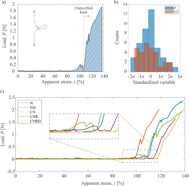
Figure 2. (a) A typical load versus strain curve of a polymeric knotted fibre under a tensile load. The area under the curve (filled in light blue) is directly correlated to the toughness modulus of the fibre, T. The presence of the knot generates a plastic-like plateau during the unravelling. Once the knot unties completely, the curve collapses to that of an unknotted fibre with underling area T0 (marked with solid lines); the toughness modulus increase due to the knot can be obtained by equation (7). (b) Comparison between the distribution of the load at failure P and the toughness modulus increase % T recorded for the tested fibres; contrary to P, % T does not follow a normal distribution but depends on the sample preparation. (c) Example load–apparent strain curves of differently prepared microfibre samples, as defined in table 1.
Download figure:
Standard image High-resolution imageAs it emerges from the tensile tests (example load-apparent strain curves for each sample are shown in figure 2(c), while details about the mechanical properties derived from all the tensile tests are reported in the Supplementary Information), the only presence of the noose seems not to be sufficient to improve significantly the fibres toughness. Indeed, the toughness modulus increase T % results not to be more than 2.3%. On the other hand, the presence or combination of additional smart structures, like knot and silicone coating or silicone droplet or surface roughness enabled a higher toughness modulus increase, which in the case of samples CNR and CNRD was as high as 24% and 14%, respectively. A higher toughness increase in such cases can be related to a higher amount of energy dissipated by friction during knot unravelling, which appears in the load-apparent strain curves as local peaks and drops (partial loading and unloading events as shown in the inset of figure 2(c)). Nevertheless, we can notice that fibres with a rough coating (CNR) show, on average, a lower load at failure P, which could be directly related to the surface roughening treatment.
In order to gain a deeper insight into the role played by the various features added to the polymeric fibres (table 1) on both P and % T, and to evaluate the contribution to those with a rigorous statistical approach, we considered to apply the CA, as reported in the following subsections.
CA for the load at break P
As the load follows a normal distribution (figure 2(b)) with the mean value  and standard deviation
  we identified the following three balanced categories: (i) Low, for
  (ii) Medium, for
  and (iii) High, for
The resulting contingency table is then reported in table 2.
Table 2. Contingency table related to the load at break P of all the samples.
| Sample | Low P | Med P | High P | Number of tests |
|---|---|---|---|---|
| 0 | 1 | 5 | 3 | 9 |
| C | 1 | 2 | 1 | 4 |
| N | 0 | 1 | 3 | 4 |
| ND | 3 | 3 | 1 | 7 |
| CN | 1 | 2 | 2 | 5 |
| CNR | 6 | 0 | 0 | 6 |
| CNRD | 4 | 2 | 1 | 7 |
| Tot | 16 | 15 | 11 | 42 |
Since the table has 7 rows (plus the total) and 3 columns (plus the total), the resulting Euclidian space is a plane (K = 2), with two axes that contain the total inertia of the groups. The first axis accounts for the 84.6% of the total inertia, thus it well approximates the variation among samples. The results of the CA performed with Past 4.02 are reported in figure 3 with rows in principal coordinates. The points, whose coordinates are an output of the software, are almost concentrated around the origin, with few exceptions (samples CNR and N) that are discussed in the next section. Absolute and relative inertia contributions for each row are reported in table 3, which shows that sample CNR contributes by more than 50% to the principal inertia λ1 associated to the first axis. Owing to this high value, it is necessary to check whether this point can cause internal instability to the first axis. By applying equation (1) with k equal to 1, the relationship is satisfied (0.16 > 0.08), thus the axis is stable and the upper bound of Φ6,1 results to be 26° according to equations (2)–(4).
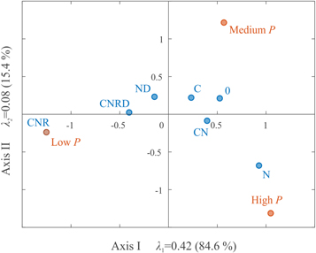
Figure 3. Correspondence analysis of the data in table 2 where the points obtained with software Past 4.02 are displayed in the principal plane. The inertias λ1 and λ2, with their percentages, are reported on their respective axes.
Download figure:
Standard image High-resolution imageTable 3. Masses wi , absolute contributions of the points to the principal axes and relative contributions of the axes to the points obtained from the CA samples versus load at failure P.
| Sample | Masses wi | Absolute contribution to axis I | Relative contribution cos2 θi,1 | Absolute contribution to axis II | Relative contribution cos2 θi,2 |
|---|---|---|---|---|---|
| 0 | 0.21 | 0.14 | 0.86 | 0.13 | 0.14 |
| C | 0.10 | 0.01 | 0.53 | 0.06 | 0.47 |
| N | 0.10 | 0.20 | 0.65 | 0.58 | 0.35 |
| ND | 0.17 | 0.01 | 0.28 | 0.12 | 0.72 |
| CN | 0.12 | 0.04 | 0.95 | 0.01 | 0.05 |
| CNR | 0.14 | 0.53 | 0.97 | 0.11 | 0.03 |
| CNRD | 0.17 | 0.06 | 1.00 | 0.00 | 0.00 |
CA for the toughness modulus increase % T of knotted fibres
Since the entire distribution of the toughness across of the samples cannot be described as a normal function, but depends on the sample preparation (figure 2(b)), we identified for % T four balanced categories: (i) Low, for  (ii) Medium, for
  (iii) Med-High, for
  (iv) High, for
  Hence, the associated contingency table has 5 rows and 4 columns, as shown in table 4.
Table 4. Contingency table related to the toughness modulus increase of knotted fibres.
| Sample | Low % T | Medium % T | Med-High % T | High % T | Number of tests |
|---|---|---|---|---|---|
| N | 3 | 1 | 0 | 0 | 4 |
| ND | 1 | 5 | 1 | 0 | 7 |
| CN | 1 | 2 | 1 | 1 | 5 |
| CNR | 0 | 0 | 1 | 5 | 6 |
| CNRD | 0 | 1 | 5 | 1 | 7 |
| Tot | 5 | 9 | 8 | 7 | 29 |
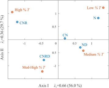
As for the load P, also for the toughness increase we reported the graphical representation of the CA with rows in principal coordinates. The resulting Euclidian space has three axes (K = 3), with the first two axes which account for the 84.7% of the total inertia; thus, if we refer to a 2D plane defined by the principal axes, the correlations that can be drawn among points reflect the reality with sufficient accuracy (figure 4).
Figure 4. Correspondence analysis of the data in table 4 where the points obtained with software Past 4.02 are displayed in the best-fitting principal plane. The inertias λ1 and λ2, with their percentages, are reported on their respective axes.
Download figure:
Standard image High-resolution image
In this second analysis, the clouds of points are more scattered with respect to the origin, thus meaning that the sample preparation has a significant influence on the resulting toughness modulus increase. As before, the stability of the principal axes has to be verified, since sample CNR accounts for up to 47% of the first inertia λ1 (results reported in table 5). However, equation (1) is still satisfied, being 0.27 > 0.24, and the upper bound of Φ4,1 results to be 43° according to equations (2)–(4). A similar check can be performed with respect to the second axis, since the absolute contribution of point CNRD is up to 41% of the second inertia λ2. By applying equation (1) with k = 2, the relationship is satisfied (0.16 > 0.12), with an upper bound of Φ5,2 equal to 19°. In summary, we can infer that our analyses are stable and thus the qualitative correlations between sample preparation and resulting mechanical properties discussed in the following section can be considered significant from a statistical point of view.
Table 5. Masses wi , absolute contributions of the points to the principal axes and relative contributions of the axes to the points obtained from the CA samples versus the increment of toughness % T.
| Sample | Masses wi | Absolute contribution to axis I | Relative contribution cos2 θI,1 | Absolute contribution to axis II | Relative contribution cos2 θI,2 |
|---|---|---|---|---|---|
| N | 0.14 | 0.30 | 0.68 | 0.26 | 0.32 |
| ND | 0.24 | 0.16 | 0.83 | 0.06 | 0.17 |
| CN | 0.17 | 0.01 | 0.95 | 0.00 | 0.05 |
| CNR | 0.21 | 0.47 | 0.77 | 0.26 | 0.23 |
| CNRD | 0.24 | 0.07 | 0.23 | 0.41 | 0.77 |
Discussion
The extent to which a point representing a row relates to a point representing a column profile depends on their distance in the CA plot. In particular, if the points lie in the same quarter of the graph their relationship is strong (high correspondence). Thus, from the spread of orange or blue points (corresponding to the rows profiles i.e., sample types and columns profiles i.e., specific P or % T values, respectively) in figures 3 and 4, we can understand how a specific sample preparation (i.e., knot, localized silicone droplet or surface roughening or combination of those) influences the mechanical properties.
For example, in figure 3 we can see that the most significant variations in terms of load bearing capability are observed along the horizontal direction, since the first inertia λ1 accounts for 84.6% of the total, meaning that the first axis represents, for the most part, the load behaviour. CN and N points lie in the quarter of high P values, thus confirming that the presence of the knot, with or without the coating, does not introduce any damage to the fibre itself. Similarly, samples 0 and C are close to each other, thus meaning that also the coating has no effect on the load bearing capability. This latter observation matches the results derived from the t-Student analysis shown in the previous section. On the contrary, CNR perfectly overlaps the low P point, supporting our experimental observations that the roughness, even if it could increase the energy dissipated by the knotted fibres thanks to friction, has a negative impact on the load at failure. However, this effect can be attenuated through the deposition of a localized silicone droplet on the knot of rough fibres, i.e., CNRD is on the right side of CNR, thus more close to Medium P and High P points; thus it seems to restore the initial load bearing capacity.
Figure 4 provides useful insights in how different sample processing influences the toughness modulus. Firstly, there is a remarkable division between the categories 'High' and 'Med-High' (negative side) with 'Medium' and 'Low' (positive side) along the first principal axis, which counts for 55% of the total inertia. Secondly, such division can be similarly observed amongst the sample types, thus allowing to easily identifying those characterized by the highest or lowest toughness increase. For example, sample N is located in the neighbourhood of Low % T point, which confirms that the presence of the knot alone cannot provide significant benefits to the fibre toughness; however, when the knot is combined with a localized drop of silicone, the toughness modulus increases to medium values (point ND lies in the neighbourhood of Medium % T). The coating roughening combined with the knot resulted as able to remarkably contribute to enhance the dissipated energy; indeed samples CNR and CNRD are close to high and med-high values of % T, respectively. Such toughness enhancement could be related to a successful interaction and friction generation between the knot and the rough coating, which was observed during sample preparation (figure 1(i)) to tend to accumulate at the knot location, during the fibre loading. Point CN has the most interesting position, since it is close to the centre and does not tend to any specific % T values, due to a high values variance. Indeed, its absolute contributions to the inertia of both principal axes are almost zero (table 5). However, since the relative contribution of the first axis to that point, cos2 θ3,1 , is almost 1, it means that the horizontal axis well represents the point's properties: moving from the left to the right in the horizontal direction, the % T decreases. Since point CN lies in the right quadrants, it means that it is better described by Low or Medium % T. On the contrary, with respect to figure 3, CN could be more straightforwardly categorized as provided with medium or high load at failure.
Conclusions
It was proved in our previous works [13, 15, 16] that a mechanical sink (i.e., a knot) can increase the energy dissipated by a fibre when this latter is loaded under tension, resulting in an enhancement of its toughness modulus. The application of a statistical approach, such as the correspondence analysis (CA), confirmed that the presence of a knot alone is not always sufficient to reach significant gains in the toughness modulus of high-performance polymeric microfibres; whereas the combination of the knot with other features, such as a viscoelastic coating, resulted to be more efficient. It was also observed from the results, and then supported by the CA, that a rough surface contributes significantly to the fibre's energy dissipation capability not only in the case of biological materials [15, 16], but also for synthetic ones. Moreover, our approach revealed that the CA can provide both qualitative and quantitative information about the relationship between sample preparation and resulting mechanical properties, thus allowing to identify the most effective treatments and successfully guiding the design of smart materials with improved mechanical performances.
Acknowledgments
The authors would like to thank Marco Polese for his contribution to sample preparation.
Data availability statement
All data that support the findings of this study are included within the article (and any supplementary files).
Funding sources
This work was supported by Fondazione CARITRO, Cassa di Risparmio di Trento e Rovereto, No. 2019.0216.
Author contributions
All authors have given approval to the final version of the manuscript. A B and M F P realized the samples and performed the experimental tests. A B realized the statistical analysis, A B and M F P analyzed the results and wrote the manuscript. A B, M F P and N M P designed the study, N M P helped in rationalizing the results and drafting the manuscript.
Footnotes
- 5
The apparent strain is evaluated as the length variation of the knotted fibre with respect to the initial end-to-end length l0 [13].