
Abstract
The paper aims to give the step by step design procedure of an electromagnetic bearing having eight pole for machine tool applications having the shaft diameter of 20 mm and rotate with the speed of 750 rpm. The mathematical procedure consists of the geometrical as well as constraints due to losses occur in the electromagnetic bearing which makes the designing more accurate. Finally, optimization has been done to get the optimum values of the dimension of the electromagnetic bearing. By interior trust method numerical optimization has carried out to find out the optimum values of the dimensions of an electromagnetic bearing to maximize the electromagnetic force exerted by it. This has supported by a CAD model using Solid Works showing the dimensions of the model. The mathematical model compared with the available literature on electromagnetics bearing and found to be an effective with consideration of all iron and copper losses. The results show the designed bearing can produce a magnetic force of 166 N from each electromagnet on the shaft. For the application an electric hand drill machine has to be taken and an electromagnetic bearing consists of 8 electromagnets has been designed which is capable of generating 29 N of electromagnetic force onto the shaft of the electric hand drill machine.
Export citation and abstract BibTeX RIS
1. Introduction
An electromagnetic bearing works on a principle in which electromagnetic force is used to levitate the shaft which will generate when current passes through the copper wires [1]. Electromagnetic bearing is a type of an active magnetic bearing [2, 3] in which an active and continuous feedback is generated regarding the position of the shaft so that it will maintain in its original position. Hence the rotor (shaft) and the stator will be separated from each other to minimize the friction and losses due to friction will eliminate which results in higher operation speed, less maintenance cost and higher bearing life. Due to many advantages active magnetic bearings have wide area of applications, such as in machine tool systems, magnetically levitated vehicle, high-speed turbines, flexible rotor dynamic systems, compressors, etc [3] as compared to passive magnetic bearing. Madhura and Govindaraju [1] design and test an active magnetic bearing having eight pole configurations, by taking the value of current and number of turns per pole as constant to find out the inductance, flux density and magnetic force which are used to levitate the rotor. The constraints related to losses were not considered. Further the modelling of active magnetic bearing has been done on solid edge ST5 and for its fabrication; stator will be made up of sheet steel because of its better permeability and saturation level and for winding copper wire has been used. Lijesh and Hirani [4] also give an optimum procedure to design an 8-pole active magnetic bearing by considering the geometric as well as constraints related to copper and iron losses. The equations related to geometric constraints which are wire diameter, number of turns, and dimension of poles have been formulated. By taking the values of axial length, outer diameter of the stator and radial air gap constant magnetic force has been calculated. By the help of numerical optimization method, the value of levitation force has been maximized. Ludvig and Kuczmann [5] analyzed an active magnetic bearing by the finite element method and magnetic vector potential formulation. The value of current and number of turns has to be taken as constant in the entire calculation and by FEM applying through COMSOL Multiphasic software the magnetic force is to be maximized. Kumar et al [6] design of an active magnetic bearing to minimize the rotor vibration for enhances the overall performance of the system. The active magnetic bearing will have a 12 pole configuration. In design methodology of radial active magnetic bearing the values of maximum load capacity, air gap and number of poles are taken as constant in the entire calculation. Hsiao et al [7] provides an optimum design procedure of an active magnetic bearing for optimizing the loadcarrying capability and force slew rate (i.e. change in voltage per unit time) by constraining the bearing geometry so to increase the performance of magnetic bearing to levitate the rotor. The constraints related to copper and iron losses which also play a major role in performance of an active magnetic bearing did not consider in the design procedure.
After an exhaustive literature on electromagnetic bearing it can be seen that researchers have worked on either on the electrical losses occur in an electromagnetic bearing or on the geometrical constraints. In this paper an electromagnetic bearing has been designed for the spindle having diameter off 20 mm of a drilling machine by considering geometrical constraints like number of poles, outer diameter, and radial air gap, diameter of the shaft (i.e. diameter of spindle of the drilling machine) and the length of the electromagnetic bearing as well as the constraint related to losses occur in electromagnetic bearing to maximize the force applied by the electromagnets which is used to levitate the rotor by optimizing all parameters through interior trust method by the help of MATLAB toolbox.
Figure 1 shows an 8 pole electromagnetic bearing where, Wpis the pole width, L is the length of the bearing, Ws is the outer rim thickness of the stator, Dshaft is shaft diameter, Dstator represents stator's outer diameter, G is the radial air gap and α represents the half angle made by the two repetitive poles at the center of the bearing.

Figure 1. Sketch of an Electromagnetic Bearing.
Download figure:
Standard image High-resolution image2. Methodology
While designing an electromagnetic bearing, some initial parameters are to be taken as input which is constant throughout the calculation and then the formulation and other steps has to be followed. Figure 2, shows the sequence of methodology used in the designing of an electromagnetic bearing.

Figure 2. Flow chart showing the design methodology.
Download figure:
Standard image High-resolution image3. Considered parameters
Table 1 shows the initial parameters which are to be taken as constant in the entire formulation as well as calculation to find out the values of parameters such as pole width, wire diameter, number of turns around one pole and maximum force exerted by the electromagnetic bearing to levitate the shaft or rotor.
Table 1. Parameters considered for the electromagnetic bearing.
| Parameters | Values |
|---|---|
| Outer Diameter (Dstator) | 100 mm |
| Radial air gap (G) | 0.5 mm |
| Shaft Diameter (Dshaft) | 20 mm |
| Bearing Length (L) | 35 mm |
| Saturation of the material (Bsat) | 1.4 T |
| Copper current density (ξ) | 6 A mm−2 |
| Loss due to magnetic flux leakage (η) | 0.75 |
| Maximum current (Imax) | 5 A |
| Natural Convection Coefficient (h) | 10 W m−2 K |
| Coefficient of Thermal Conductivity (K) | 2.5 W/m K |
| Winding Temperature (T1) | 65 °C |
| Ambient Temperature (Ta) | 35 °C |
| Resistivity (ρ) | 1.68 × 10⁻⁸ Ω m |
4. Formulation
The electromagnetic force generated by an electromagnet to levitate the shaft, is given as [4]

Here, N is the number of turns per coil, I is the current flow in the copper wire, AG is the area of the air gap for one pole, μ0 represents magnetic permeability of a vacuum and η is the efficiency of the electromagnetic bearing which affect by the magnetic flux leakage and vary from 0.6 to 0.9, for very closely spaced poles with leakage to very well spaced with low leakage respectively.
In current work 8 pole configurations has to be taken while designing an electromagnetic bearing because of their high load carrying capacity and compactness for the same input parameters such as current, number of turns, pole area and air gap as compared to the 4 pole and 3 pole configuration electromagnetic bearing [8].The core is made up of soft iron and the winding is made up of copper wire, and the design procedure will be based on two constraints which are geometrical constraints and constraints due to losses.
4.1. Geometrical constraints
The geometrical constraints include the constraints related to wire diameter, area of pole, outer diameter as well as inner diameter of the stator, winding constraints. By taking geometrical constraints into account there will not be any physical contact occur between the stator and the rotor and wire can be easily wound onto the poles without touching the wire wounded on the neighbor pole.
In figure 3, w is the winding thickness, Lw is the winding length, Lp is the pole length, Wp is the pole width.

Figure 3. Electromagnetic bearing showing winding constraints.
Download figure:
Standard image High-resolution imageConstraint due to inner diameter of the stator
The magnetic field generated by the electromagnets will affect the sensors so to avoid this shaft will made up of paramagnetic material. A ferromagnetic ring having thickness Wshaft is placed on the shaft to increase the attractive force between the shaft and the bearing. In current work, we assume that Wrotor = Wp = Ws, which ensure the same saturation limit for the magnetic flux density. Hence the pole diameter dp will be

Constraint due to wire diameter
The maximum current flowing through the wire will be proportional to the wire diameter and the current density. The current density (ξ) for a copper wire is limited to 6 A mm−2 [7].

Constraint due to area of pole
The magnetic flux generated between the air gaps in the electromagnetic bearing will be less than equal to the material's saturation limit, hence

Constraint due to the outer diameter of the stator
The constraint due to outer diameter of the stator will be,

Where, t is gap given at the bottom of the pole for avoiding loosening of winding during operating condition.
Constraint due to winding
To ensure the minimum gap of 2dw between the two consecutive pole tips, and to avoid contact between the winding tips [4, 9] the following condition must be satisfied

To provide sufficient space between the windings constraint related to winding space must be accounted wile designing electromagnetic bearing. The maximum length of the wire that can be wound around the pole [7, 10] approximated equal to the 80% of the actual pole area, hence

If the coils are connected in such a way that the pole polarization sequence is N-S-N-S-N-S-N-S, then Wrotor = Ws = Wp/2 and for pole polarization sequence N-S-S-N-N-S-S-N, Wrotor = Ws = Wp will remain same [3].
4.2. Constraints due to losses occur in an electromagnetic bearing
The losses occur in electromagnetic bearing affect its life as well as its performance. There are two major kind of losses occur in electromagnetic bearing, copper losses and iron losses. Due to the current flowing in the copper wire in each pole, copper losses occur whereas by using the ferromagnetic material for both the stator and the rotor, iron losses occur.
Copper losses
As we know that in a current carrying wire the heat generation will be,

Where, I is the current supply and R is the resistance and the value of R will be,

Where ρ is the resistivity and lw is the total wire length.
Copper losses occur due to the resistance occur in the path of current flow which lead to heat generation, which is transferrable due to the conduction, convection and radiation. The value of radiation is considered negligible in present calculation due to the very less value of the Stephan Boltzmann constant which is 5.67 × 10⁻⁸ W m−2K−4.
Heat dissipation due to conduction as per the Fourier's law is given as [11]

Where, T1 is the temperature of the winding and Ta is the temperature at the ambient. K is the thermal conductivity of the material which will be considered 2.5 W m−1 K−1 in the present work [4].
Heat dissipation due to convection as per the Newton's law of convection is given as

Where, S is the total surface area of contact between the fluid (i.e. air) and the solid and h is the natural convection coefficient, the value of h in the present work is taken as 10 W m−2K−1 [12].

Iron losses
Iron losses happen in the electromagnetic bearing are mainly due to the eddy current which will be reduces by using the laminated materials between each poles and the hysteresis losses.
The values of eddy current and hysteresis losses will be given as [12, 13]
And,

Where, t is laminated core thickness, l is the pole length, ƒ is the frequency of the rotation and is taken 50 Hz in present work for the shaft rotation of 750 rpm, V is the volume of the conductor, n is the number of domain per unit volume and given by,

And Kh is the coefficient of hysteresis and given by,
Hence the value of iron losses occur in electromagnetic bearing,

The total losses in the electromagnetic bearing will be calculated by

To increase the working life spam of the electromagnetic bearing the heat generation must be less than the heat dissipation,

5. Calculation
By putting all the considered parameters in the equations (1) to (15) we get,
From equation (3),

From equation (4),

From equation (6),

From equation (7),

From equation (15),


From equation (1) the maximum force applied by an electromagnet on the rotor,

6. Results
In the present work, numerical optimization has been done by the use of MATLAB by 'Interior Trust' method. In numerical optimization method the objective function which is the equation (F) is either minimized or maximized subjected to its constraints [13]. Hence thefinal equation (21) represent the max (F) equation was converted to a minimization objective function for our optimization procedure hence can be written as,
The equations from (16) to (20) can be written as giving the nonlinear constraints,


The values of objective function with respect to number of iteration have been representing by a graph shown in figure 4.

Figure 4. Graph between the function value and the number of iteration.
Download figure:
Standard image High-resolution imageThe number of iterations required for the finding the optimum solution is 30 and the value of maximum force exerted by the electromagnetic bearing has to be found out 166 N. The values of other unknown parameters are tabulated in table 2.
Table 2. Results using numerical optimization.
| Parameters | Values |
|---|---|
| Pole width Wp (mm) | 17.5 |
| Wire diameter dw (mm) | 1.3 |
| Maximum current Imax (A) | 5.67 |
| Number of turns N | 106 |
| Force (N) | 166 |
Hence each electromagnet of electromagnetic bearing is capable to generate the magnetic force of 166N which can levitate the shaft having diameter 20 mm rotate with a speed of 750 rpm.It will use in the milling machine [14] to control the chattering effect which is self-induced vibration. The electromagnetic bearing will also be used in the machine tool applications like in micro milling machines [15], lathe machines and other high speed machining operations [16] because of their better working precision and compactness [17–2017-20].
7. Modeling
The modeling of electromagnetic bearing has been done in Solid Works software. The 2D and 3D model of Electromagnetic bearing has been shown by figures 5 and 6.

Figure 5. 2D model of electromagnetic bearing.
Download figure:
Standard image High-resolution image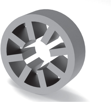
Figure 6. 3D model of electromagnetic bearing.
Download figure:
Standard image High-resolution image8. Application: electric hand drill machine
In application of the electromagnetic bearing we take a hand electric drill machine, disassemble it as shown in figure 7. The electric drill machine will run by an electric motor hence the name. The specification of the hand electric drill machine we use is that it needs 220 V and 50 Hz for its operation and the drill rotation speed is 2600 r min−1 and the drill bit used for this is of 10 mm size.

Figure 7. Electric hand drill machine configuration.
Download figure:
Standard image High-resolution imageThe disassembled electric drill machine consists of a chuck having a jaw for which hold the drill bit of size 10 mm, a power cord for the electric supply, an armature assembly (figure 7) and outer housing which provides a shell for these parts.
The figure 8 shows the front or top view of motor assembly of the electric drill machine. This consists of an armature consisting of coils which generates enough power to rotate the shaft and hence the drill bit, a gear arrangement, two bearings. The bearings provide the stability to the entire system so there is no vibration while drilling. The bearings used are ball bearings hence due to mechanical contact between surfaces there is friction which increases the mechanical losses decreases the efficiency as well as the life of the system [21–2421-24].
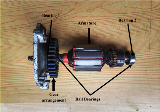
Figure 8. Front view of the motor assembly of the electric drill machine.
Download figure:
Standard image High-resolution imageHence the aim is to replace these ball bearings with the proposed electromagnetic bearings, which increases the life as well as rotation speed of the drill bit.
The bearing 1 and bearing 2 used in the electric drill machine will show in the side view (figure 9).
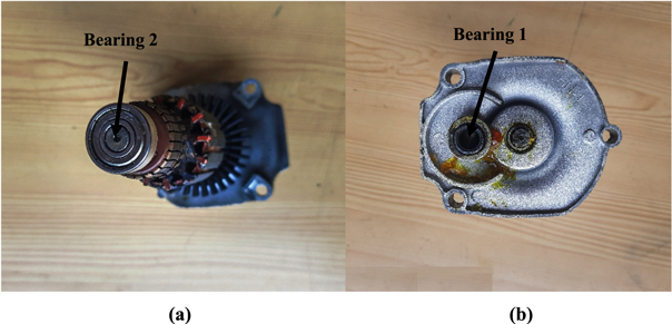
Figure 9. Side views of the motor assembly of electric drill machine (a) Right side view (b) Left side view.
Download figure:
Standard image High-resolution imageBy use of vernier scale the dimension i.e. outer diameter, inner diameter, shaft diameter has been measured of these bearings which are mention in table 3.
Table 3. Parameters measured from the bearing used in hand drill machine.
| Parameter | Value |
|---|---|
| Outer Diameter (Dstator) | 19.1 mm |
| Radial air gap (G) | 0.5 mm |
| Shaft diameter (Dshaft) | 7 mm |
| Bearing length (L) | 6 mm |
| Saturation of the material (Bsat) | 1.4 T |
| Copper current density (ξ) | 6 A mm−2 |
| Efficiency of electromagnetic bearing (η) | 0.75 |
| Maximum current (Imax) | 4 A |
| Natural Convection Coefficient (h) | 10 W m−2 K |
| Coefficient of Thermal Conductivity (K) | 2.5 W/m K |
| Winding Temperature (T1) | 65 °C |
| Ambient Temperature (Ta) | 35 °C |
| Resistivity (ρ) | 1.68 × 10⁻⁸ Ω m |
By putting all the considered/measured parameters in the equations (1) to (15) we get the results whose numerical optimization has been carried out with the help of MATLAB by using 'Interior Trust' method to find out the optimal values of each unknown parameters. Hence the equation for the max (F) can be written as,

The nonlinear constraints are given as


The values of other unknown parameters getting through optimization are tabulated in table 4.
Table 4. Results using numerical optimization for the hand drill machine application.
| Parameter | Value |
|---|---|
| Wp (mm) | 3.5 |
| dw (mm) | 0.5 |
| Imax (A) | 2.9 |
| N | 34 |
| Force (N) | 29 |
2D and 3D model of Electromagnetic bearing has been shown by figures 10 and 11 respectively.

Figure 10. 2D model of electromagnetic bearing for hand drill application
Download figure:
Standard image High-resolution image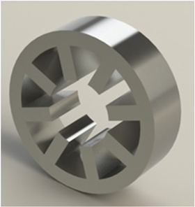
Figure 11. 3D model of Electromagnetic Bearing for hand drill application.
Download figure:
Standard image High-resolution image
Figure 10 shows the stator of the electromagnetic bearing consist of 8 electromagnets which is capable of generating 29 N electromagnetic force onto the shaft of the electric hand drill machine to levitate it in its original position. The above electromagnetic bearing is capable of replacing the ball bearings present in the electric hand drill machine which has the drill rotation speed of 2600 r min−1.
9. Conclusion
In this paper a design procedure has been detailed and implemented on a hand drill machine for the designing of an 8-pole electromagnetic bearing. An electromagnet has been designed for the given outer diameter, length of the bearing and air gap to provide maximum magnetic force. The magnetic force has been maximized for the given constraints by numerical optimization method which is donewith the aid of MATLAB using the interior trust method. The modeling of electromagnetic bearing has been done in the Solid Works.