
Abstract
In a cryomodule, bellows are commonly used to connect two adjacent superconducting cavities. It provides cavities a mechanical flexibility facilitating for thermal contraction or expansion during temperature transitions. While heat from superconducting cavities are removed from helium flowing through their jackets, non-superconducting bellows are cooled down through a relatively slow process of conduction cooling by adjacent superconducting cavities. An excessive heat deposition to the bellows could results in unsustainable rise in temperature that could lead to a thermal runaway. Because of the bellows proximity to the superconducting cavities, resulting thermal runaway could disrupt performance of the cavities and therefore, overall operation. For this reason, the paper presents a comprehensive assessment of RF heating resulting from most potent dynamic heating mechanisms in the interconnecting cavity bellows of 1.3 GHz, continuous wave, cryomodule of the Linac Coherent Light Source-II linear accelerator. Studies are performed for two types of the bellows surfaces i.e. stainless-steel and copper. The results show that RF heating at stainless-steel surface is about four times higher than at copper surface. In this work we also develop a simplified analytical model to analyse the bellows surface temperature growth resulting from RF heating. The model shows a good agreement with numerical analysis and indicates a temperature growth of up to 70 K in stainless-steel bellows in the steady state. Calculations also show that a thin copper coating of 15 μm on stainless-steel surface not only reduces RF heating but also confines the temperature growth well within 10 K. The studies presented here attribute practical importance guiding to characterize copper coating requirements for non-superconducting components in a cryomodule and allowing to model a more relevant cryogenic heat load budget accounting for bellows heating.
Export citation and abstract BibTeX RIS
1. Introduction
The particle accelerator-based next generation light sources require a high energy electron beam with high repetition rate to produce brighter x-rays that would eventually be a tool to enhance our understanding about rare biological and chemical processes. Superconducting Radio Frequency (SRF) technology is the foremost choice for such applications involving accelerators operating in long-pulse or continuous-wave (CW) RF regimes. Newly proposed or under construction light-source facilities such as Linac Coherent Light Source-II (LCLS-II) [1, 2], European x-rays Free Electron Laser (XFEL) [3], Shanghai Coherent Light Facility (SCLF) [4] are based on the SRF linear accelerator. It is evident that the major infra-structure investment and operational costs of the SRF accelerator facilities are primarily outlined by its cryogenic requirements. Consequently, it is critical not only to evaluate cryogenic heat loads originating from various sources with a great care but also to constraint them at minimum especially in the cavity operating environment of 2 K where cryogenic efficiency of removing a Watt of dissipated power is least.
The SRF cavities are building blocks of the accelerator. These cavities are accommodated in the cryomodules. Periodic arrangement of those cryomodules delineate a major portion of the beam transport line in an SRF accelerator. Thus, one can easily infer that cryogenic loss per cryomodule needs to be minimized to lower the overall capital and operational cost of a cryogenic system in an SRF accelerator. Consequently, detailed investigation and assessment of various heat sources in operational cryogenic environment always has been one of the main considerations of the design, fabrication and commissioning of a cryomodule, as also indicated by volume of previous studies [5–15] performed in framework of different cryomodules built for a number of superconducting accelerator facilities. This in turn, allows to develop appropriate mitigate strategies to optimize thermal performance of a cryomodule and hence, entire facility.
A cryomodule usually houses multiple cavities. Two successive cavities in a cryomodule are connected through the vacuum tight bellows assembly that provides a mechanical flexibility allowing for length contraction (or expansion) during a cool-down (or warm-up) of the cavities. While RF heat from surface of the cavity is removed by helium flowing through the helium jacket, heat from the superconducting beam pipe outside of the helium jacket and non-superconducting bellows assembly are removed through a relatively slow process of conduction cooling by adjacent SRF cavities operating at 2 K. Temperature of the bellows-ends can be up to 4 K in a steady-state. Thus, an excessive heating of the bellows could cause an unsustainable rise in its temperature. An abrupt increase in the bellows temperature might produce conduction heating of the beam pipe and the SRF cavity due to their close proximity to the bellows which leads to an increase in their Bardeen-Cooper-Schrieffer (BCS) surface RF resistance,  [16] that scales with temperature as follows:

where f0 is operating frequency of the cavity in this case, Δ is half of the energy gap between the first excited state and ground state, kb , T are Boltzmann constant and surface temperature respectively. A high surface resistance implies more power dissipation and therefore, more heating. This in turn, not only enhances the cryogenic load at 2 K environment but also limits high field RF performance of the cavities [16–19]. The accumulated heat in the cavity end-group could eventually lead to a thermal quench [20–22]. This is why a careful evaluation of RF heating in a non-superconducting bellows in vicinity of the superconducting elements needs to be performed. It becomes mandate especially for a CW and high intensity beam operation where additional heating resulting from wake fields [23] and operating fields could be substantial and could disrupt overall operation if not accounted for properly in the design. For this reason, the paper thoroughly addresses the most imperative dynamic heating mechanisms in the bellows induced by the beam and operating fields. The resulting heating is then computed for the 1.3 GHz, CW, SRF cryomodule of the LCLS-II linac considering two types of the bellows surfaces i.e. stainless-steel and copper. Furthermore, the paper details temperature distribution across the bellows and discusses implication of copper coating on the temperature growth.
The paper is organized in six sections. In section 2, a brief overview of the LCLS-II operational parameters and 1.3 GHz cryomodule is provided. Section 3 systematically details bellows heating resulting from operating mode fields of the cavity, wake-fields and higher order trapped modes in the LCLS-II cryomodule. An analytical approach developed to calculate temperature distribution in the bellows is presented in section 4, while implications of copper coating on stainless- steel bellows are discussed in the section 5. The paper concludes with a summary in section 6.
2. 1.3 GHZ LCLS-II cryomodule
The LCLS-II is a Free Electron Laser (FEL) facility under construction at SLAC national accelerator laboratory in USA. The facility is primarily based on a 4 GeV, SRF electron linear accelerator that would operate in a CW regime. To obtain the designed beam acceleration, the linac uses thirty-five 1.3 GHz cryomodules. Each cryomodule consists of eight 9-cells, 1.3 GHz elliptical shaped cavities developed for International Linear Collider (ILC) and TESLA projects [24–26]. In addition, the cryomodule also includes a magnet package comprising a quadrupole magnet, horizontal and vertical steering correctors and, the beam position monitor at its downstream end. Figure 1 shows schematic of the LCLS-II, 1.3 GHz cryomodule highlighting some of its crucial elements and cross-sectional variations in the beam-line vacuum chamber geometry along the cryomodule. It will be discussed in subsequent section that these geometrical variations are primary source of scattered wake fields as the beam traverses through the linac. To minimize the wake fields heating in a 2 K environment, a Higher Order Modes (HOMs) absorber is installed between two cryomodules in the beamline. Note that, the absorber is connected to 70 K cooling circuit. Additional details about the cryomodule design and fabrication have been presented elsewhere [12, 27, 28].
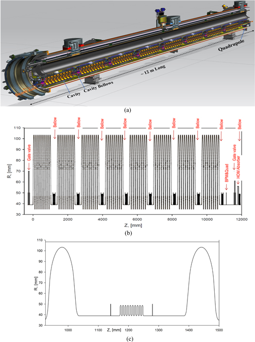
Figure 1. (a) 3D rendering of the 1.3 GHz, LCLS-II SRF cryomodule illustrating beam transport line. (b) Detailed 2D schematic of the beam transport line in cryomodule with transverse and longitudinal coordinates around the beam axis highlighting eight cavities, interconnecting cavity-bellows, quadrupole magnet etc along the cryomodule. Note that, HOMs absorber is installed outside the cryomodule (c) A zoomed view of interconnecting cavity region showing the bellows assembly (bellows and two flanges represented by two vertical lines) and last cells of two adjacent cavities.
Download figure:
Standard image High-resolution imageThe accelerating cavities in the LCLS-II cryomodule operate at 2 K with nominal accelerating gradient of 16 MV m−1. As shown in figure 2, besides an input RF power coupler, each cavity is equipped with two HOMs couplers that facilitate extraction of HOMs fields from 2 K environment and therefore, limit HOMs induced heating in the cavity. Figure 3 shows the bellows assembly that connects two adjacent cavities in the LCLS-II cryomodule. The assembly is composed of eight convolutions and two stainless steel flanges with a physical length, LB , of 100 mm. Because of convolution, effective length of the bellows, LBE , is larger than its physical length. It can be determined using following equation:

where, Nc is number of convolutions of the bellows. As one can notice from figure 3, LP is half period lateral length of the convolution expressed as:

where, Rsm , RL are radii of the convolutions and t is the bellows thickness. LC is convoluted length of the half period which is given as follows:

L is length of the straight part of the convolution. Effective length of the cavity-bellows in the LCLS-II cryomodule was determined to be about 0.236 m. It should also be noted that there is another type of the bellows at the upstream and downstream of the cryomodule (figure 1(b)). It facilitates connection between two successive cryomodules and has a different design from the cavity-bellows. However, we deal only with the bellows between adjacent cavities and therefore, the bellows is always referred to the interconnecting cavity-bellows everywhere in this article.
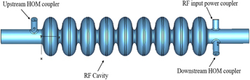
Figure 2. Schematic of a, 9-cell, 1.3 GHz cavity with input RF power and HOMs couplers.
Download figure:
Standard image High-resolution image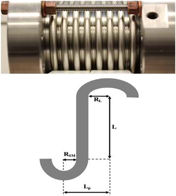
Figure 3. Picture of (top) the cavity-bellows in 1.3 GHz cryomodule and (bottom) a pictorial representation of half period of the convolution geometry.
Download figure:
Standard image High-resolution imageMost relevant beam and machine parameters of the LCLS-II linac, repeatedly used in calculations in this paper, are listed in table 1.
Table 1. Most relevant beam operational parameters of the LCLS-II SRF linac.
| Parameters | Symbol | Magnitude | Units |
|---|---|---|---|
| Bunch Charge | Qbunch | 300 | pC |
| Beam Repetition Rate | frep | 1 | MHz |
| RMS Bunch Length | σz | 25 | μm |
| Beam Average Current | I | 300 | μA |
| Beam Energy | E | 4 | GeV |
| Accelerating Gradient in Cavity | Eacc | 16 | MV m−1 |
| Operating Temperature | Top | 2 | K |
| Cavity Operating Frequency | f | 1.3 | GHz |
| Cavity Beam Pipe Radius | b | 39 | mm |
| Bellows physical length | LB | 100 | mm |
| Bellows Effective Length | LBE | 236 | mm |
| Bellows Thickness | t | 0.2 | mm |
3. RF heating in cavity bellows
The primary sources of the bellows heating in a cryomodule are leakage of operating mode fields through the beam holes in the cavity, propagating broad-band wake-fields induced by an ultra-relativistic high intensity beam traversing through geometrical variations along the cryomodule, locally trapped higher order modes and, resistive wall heating. These sources are discussed and analysed in detail in the subsequent part of the section to compute the bellows heating in the 1.3 GHz, LCLS-II cryomodule.
3.1. RF heating due to operating mode field
The beampipe at both ends of the cavity adds a perturbation to ideal modes of the resonator with closed metallic ends. This in turn, results in a leakage of the operating mode fields of an accelerating cavity into the beampipe and the bellows. The field leakage is usually low if the operating mode frequency is smaller than the cut-off frequency of the beampipe. Still, it could produce a substantial RF heating in the bellows and therefore, needs to be accounted for properly.
The operating mode field leakage to the beam pipe from the 1.3 GHz LCLS-II accelerating cavity was computed numerically using the ANSYS HFSS field solver [29]. Figure 4 shows pattern of the magnetic fields leaking through the cavity end-cells to the bellows at both ends. Note that, cavities have unequal separations from the bellows. The downstream cavity is positioned farther and therefore, only a small fraction of its fields reaches to the bellows. Resulting RF heating ( ) in the bellows is then computed using following equation:

where  is the magnetic field distribution across the bellows surface, s, resulting from the operating mode field decay and
  is the surface resistance of the bellows.

Figure 4. Operating mode magnetic field leaking through the end cell of 1.3 GHz cavity at upstream (top) and downstream (bottom) ends of the bellows in LCLS-II cryomodule. Note that the fields were normalized to nominal accelerating gradient of 16 MV m−1.
Download figure:
Standard image High-resolution imageWhile evaluating RF heating in bellows for the LCLS-II cryomodule, two cases were considered in which the bellows surfaces were assumed to be either stainless steel or copper. The microwave surface resistance is obtained from the real part of the surface impedance which is expressed for stainless steel as shown below

where  is surface impedance at angular wave frequency
 is magnetic permeability in free space and
  is electrical conductivity. Using RF frequency of 1.3 GHz,
  (1/
(1/ m) for stainless-steel, accelerating field of 16 MV m−1, RF heating in stainless-steel bellows was found to be 0.1 W.
It has been discussed elsewhere [30] that Copper with the Residual Resistive Ratio (RRR) value of a hundred exhibits extreme Anomalous Skin Effect (ASE) at frequency above 2 MHz at cryogenic temperature of 4 K. The surface impedance of copper ( ) in this regime is calculated from following equation:

where A is material constant and, for the copper it is found to be  Z0 is wave impedance in free space which equals to 376.73 Ω and c is velocity of the light. It is evident from equations (6) and (7) that the surface resistance of copper is about forty times lower than stainless steel for given parameters at 1.3 GHz. Consequently, RF heating in the copper bellows is lower than the stainless steel by the same factor and calculated to be 2.5 mW. In addition, RF heating in two stainless-steel flanges in the bellows assembly were also determined and it was computed that operating mode fields resulted in a total RF heating of 153 mW in the flanges.
3.2. Wake-fields heating
An ultra-relativistic charged-particle beam moving on the axis of a round beam pipe induces image charges on its surface. These image charges navigate alongside of the beam and create the image current. Because of a finite conductivity of the surface and cross-sectional variation of the geometrical boundaries along the beam path, the image current flow lags behind the beam. This in turn, results in trailing electromagnetic fields behind the beam that are called wake-fields.
The beam encounters several geometrical variations as it traverses through the cryomodule. These variations (as shown in figure 1) appear in the form of cavities, bellows, beam pipe in between, gate valves etc. Consequently, the beam generates scattered wake-fields (also called radiative wake-fields) as its passes through the cryomodule. These fields eventually dissipate and generate heating at various surfaces along the beamline. Total power instituted through the wake fields,  is given as [31]:

where  is the bunch charge,
  is the loss factor that determines energy lost by a bunch of unit charge in a single passage through the structure and,
  is the bunch repetition rate. A detailed analysis presented elsewhere [31, 32] shows that the loss factor per cryomodule of the LCLS-II linac has been estimated to 154 V/pC for a Gaussian bunch of RMS length of 25 μm. It results in a steady state total wake power of 13.8 W per cryomodule for the bunch charge of 300 pC and repetition rate of 1 MHz in a CW regime.
In a frequency domain, range of the wake-fields frequency spectrum can be approximated [33] as  where c is velocity of light. In the LCLS-II linac, the RMS bunch length can be as short as 25 μm and therefore, resulting wake field frequency spectrum can extend up to Tera-Hz. Thus, the total wake power can be expressed as the following:

where 
 are angular cut-off frequency of the cavity beam pipe and the highest frequency of the spectrum respectively. The first term in equation (9) represents the wake power instituted in modes below the cut-off frequency (ωc). This power is mainly localized in the cavity and, most of it can be extracted effectively from the operating cryogenic environment using HOMs couplers. Thus, it has relatively lower contribution in the overall RF heating. The second term in equation (9) has leading role in the heating. It corresponds to modes which have frequencies above cut-off frequency of the cavity beam pipe. These high frequency modes can propagate freely in the linac and make multiple reflections from surfaces of the beamline elements before getting completely absorbed. In this paper we will call them propagating or un-trapped modes. Since frequency spectrum of the propagating modes spread over tera-hertz range, estimation of their heating distribution in a cryomodule using standard numerical methods is unfeasible. The S-matrix [34] and diffusion-type model [35] approaches have been developed to address this issue. In this article we use the diffusion model to evaluate heating in bellows resulting from high frequency propagating modes.
3.2.1. Diffusion model
The diffusion model is based on assumption that the propagating modes can be treated as a photon gas distributed uniformly in the cryomodule. It is also assumed that modes dissipate all their power inside the cryomodule and therefore, no power leakage is anticipated in this model. This assumption is justifiable in presence of the long cryo-string (as it is the case for the LCLS-II linac) where power leaking out from a cryomodule is equal to power coming in from its adjacent cryomodules in a steady state. As stated earlier, the propagating modes make multiple reflections from surfaces of the beamline element and with each reflection they lose a fraction of their power. Consequently, the model considers that the power absorption is proportion to the surface impedance and surface area of elements. Thus, absorption (I) of the wake power in frequency range of  to
to  by an ith element of surface area Si
can be characterized as:
by an ith element of surface area Si
can be characterized as:

where  is real part of the element impedance at frequency
  Differential wake power,
  is computed using:

where wake impedance,  is given by

Note that s is position of the particle relative to the bunch center. In order to obtain differential wake power spectrum for the LCLS-II cryomodule, the point charge wake function of Tesla cryomodule,  with s0 = 1.74 mm, was used from [36]. H(s) is Heaviside step function. The resulting power spectrum is shown in figure 5. Then, power absorption of an ith element,
  in the cryomodule can be obtain from following expression:

where subscript j = 1, 2, 3,...n, represents beamline elements in the cryomodules as depicted in figure 1(b) (SRF cavities, vacuum chamber, bellows, gate valves etc). A detailed description of the diffusion model has also been presented in [37–39].

Figure 5. Differential steady-state wake-fields power spectrum generated by a 300 pC bunch of RMS length of 25 μm with a repetition rate of 1 MHz while passing through the 1.3 GHz LCLS-II cryomodule.
Download figure:
Standard image High-resolution imageTo determine the power absorption in the bellows, surface resistance of stainless steel and copper were computed using equations (6) and (7) over the selected range of the wake-field frequency spectrum. Figure 6 depicts their resistances over the frequency range up to 700 GHz. Then, the absorption amplitude of bellows in the LCLS-II cryomodule was computed by integrating equation (10) over the selected frequency spectrum using the knowledge of  surface area for radius of 39 mm and effective length of 236 mm. The absorption amplitude of the rest of elements in the cryomodule were computed using the same approach and then applied to equation (13) to determine the power absorption in the bellows. It was found that a stainless-steel bellows intercepted about 300 mW of total wake-fields power of 13.8 W while a copper surfaced bellows absorbed only 20 mW. In addition, a total of 40 mW of the wake-power was absorbed by stainless-steel flanges in the bellows assembly.
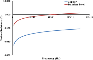
Figure 6. Variation in surface resistance of copper (blue) and stainless steel (brown) with frequency. Note that anomalous skin effect was accounted for the copper at cryogenic temperature around 4 K. Note that, origin of horizontal axis starts from 10 GHz.
Download figure:
Standard image High-resolution image3.3. Trapped higher order modes heating
There is a periodic arrangement of the cavities in an SRF cryomodule. These cavities are tuned to operating mode frequency, but their HOMs frequency spectrum can vary substantially due to mechanical variations in their geometries. This in turn, might cause reflection of lower frequency propagating modes, usually in vicinity of the beam-pipe cut-off frequency, from the adjacent cavities. Reflecting modes could get effectively trapped and form a standing wave in the beamline connecting neighbouring cavities. This in turn, can result in a localized resonance RF heating in the region.
To investigate the trapped modes in an interconnecting beamline region between two adjacent cavities in the LCLS-II cryomodule, an eigen-mode analysis for HOMs up to 5 GHz, was performed using ANSYS HFSS eigenmode solver [29]. Figure 7 shows electric field distribution of the first four trapped monopole modes. Note that, only half of the cavities (4.5 cells out of nine cells) at both ends of the beam pipe were simulated for this analysis. Table 2 summarises RF parameters of the respective modes.
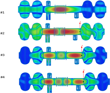
Figure 7. Electric field distributions of trapped monopole modes in the beamline between two adjacent cavities in the 1.3 GHz, LCLS-II cryomodule. RF parameters of respective modes are listed in table 2. Note that, red colour represents the highest magnitude of the field while blue colour represents the lowest.
Download figure:
Standard image High-resolution imageTable 2. RF parameters of trapped modes in beam pipe between adjacent cavities in 1.3 GHz, LCLS-II SRF cryomodule.
| Modes number | Frequency (GHz) | R/Q Ω | Qext | Ptm mW |
|---|---|---|---|---|
| 1 | 2.714 | 1.7 | 1.2E04 | 2 |
| 2 | 2.928 | 6 | 1.0E04 | 5 |
| 3 | 3.047 | 1.7 | 8.7E04 | 13 |
| 4 | 3.141 | 1.1 | 1.0E03 | 0.1 |
Resulting RF heating from a trapped mode,  is computed using the following equation:

where Ib is average beam current. It is 300 μA for the LCLS-II linac. This in turn, results in a maximum heating of 13 mW for the third mode in table 2. For a trapped mode with R/Q up to 10 Ω and Qext up to 1E + 05 (highest respective magnitudes in table 2 were rounded up to the next order), the resonance heating in the worst-case scenario might increase up to 100 mW. Since the trapped modes generate a localized RF heating, it was conservatively adopted that magnitude of heating remained the same regardless of the bellows types (copper or stainless-steel). Note that, RF anomalous heating has not been included in this estimation.
3.4. Resistive wall heating
Because of a finite conductivity of the beam-pipe, wake-fields generate ohmic losses at its surface which is termed as the resistive wall heating or parasitic heating. The loss factor per unit length, κL , in anomalous skin effect regime for short-range wake-fields approximation is obtained from [30] in form shown below

where Z0 is wave impedance in free space, b is radius of the cylindrical beam pipe and s0 is characteristic length given as

where B is a numerical coefficient determined from material properties. Its value for copper is found to be 3.9E-07 (m)2/3. For the stainless-steel bellows in a normal skin effect regime, κL [40] is calculated using the following equation

The power loss per unit length in copper and stainless bellows are then assessed by inserting respective loss factors in equation (8). Figure 8 shows variation in the resistive wall heating with RMS bunch length for the LCLS-II beam parameters. For the RMS bunch length of 25 μm, power loss gradient in copper and stainless-steel are about 0.3 W m−1 and 1 W m−1 respectively. This corresponds to total heating of 30 mW and 100 mW in respective copper and stainless-steel bellows with physical length of 100 mm.
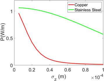
Figure 8. Resistive wall heating per unit length for copper (red) in anomalous skin effect regime and stainless-steel (green) in normal skin effect regime for Qbunch of 300 pC and frep of 1 MHz at different RMS bunch lengths.
Download figure:
Standard image High-resolution imageTable 3 summarizes RF heating in the bellows assembly from various sources in the LCLS-II cryomodule. The heating in copper and stainless-steel bellows surfaces were found to be 0.15 W and 0.6 W respectively and rest of the heating occurred in the flanges made of the stainless-steel. It is evident from here that because of a lower electrical conductivity, stainless-steel surface would cause about four times higher heating in comparison to copper surface in the bellows. Again, note that the heating occurs in 2 K environment in vicinity of an SRF accelerating cavity.
Table 3. Summary of RF heating in a cavity-bellows assembly in the LCLS-II 1.3 GHz cryomodule.
| Heating modes | Copper bellows (mW) | Stainless-steel bellows (mW) |
|---|---|---|
| Operating Mode Fields | 155 | 253 |
| Wake Field | 60 | 340 |
| Trapped Modes | 100 | 100 |
| Resistive Wall | 30 | 100 |
| Total | 345 | 793 |
4. Temperature distribution in bellows
The heat transfer in a high vacuum regime at cryogenic temperature is primary governed by the process of heat-conduction. Thus, resulting temperature rise in the bellows from the RF heating in a steady state could be obtained analytically by solving the heat-diffusion equation. Considering the heat transfer from the bellows (a heat source) to the cavity (heat-sink) is uniform and mostly in one dimension, the heat transfer can be expressed using 1D heat diffusion equation as shown below

where T, k are temperature and the thermal conductivity respectively and,  is rate of heat deposition per unit volume. The solution of above equation with boundary conditions
  is expressed as below

Figure 9 shows thermal conductivity of copper with RRR of 30 and stainless-steel 304 for a wide range of temperature ranging from cryogenic temperature to room temperature. It can be noticed from here that copper exhibits a much higher thermal conductivity than stainless-steel.
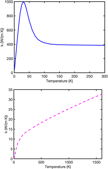
Figure 9. Thermal conductivity of (top) copper with RRR of 30 and, (bottom) stainless steel 304.
Download figure:
Standard image High-resolution imageThe bellows in the LCLS-II cryomodule was modelled as a cylindrical tube of thickness 0.2 mm and effective length of 236 mm with a radius of 39 mm. Then, temperature profiles of the bellows were obtained from equation (19) for the heat deposition of 0.15 W and 0.6 W for copper and stainless steel respectively. It was assumed that both ends of the bellows were at a fixed temperature of T1 = 4 K. Figure 10 shows temperature evolution in copper and stainless bellows in the LCLS-II cryomodule. It can easily be concluded from figure 10 that the stainless-steel bellows not only causes more RF heating but also attributes to a substantial rise in temperature due to a lower thermal conductivity at the cryogenic temperature.

Figure 10. Temperature profile of (top) copper and (bottom) stainless-steel bellows in the LCLS-II SRF cryomodule.
Download figure:
Standard image High-resolution imageTo validate analytical calculation, thermal analysis was performed using CST Studio [41] with a realistic convoluted geometry of the bellows. It can be observed from figure 11 that the maximum temperature in stainless-steel bellows found to be about 72 K for 0.6 W of heating. It reasonably agrees with a simplified but less time-consuming analytical model that predicts a maximum temperature of about 80 K.
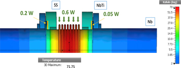
Figure 11. Temperature distribution in stainless-steel bellows assembly for a total RF heating of 0.8 W. Note that, 0.2 W dissipates at the flanges while 0.6 W at the bellows surface.
Download figure:
Standard image High-resolution image5. Copper coating
It is apparent from RF heating and thermal analyses that a copper surface is the foremost choice for a bellow. Since copper does not possess optimal material properties (such as tensile strength, yield strength) required for the bellows at cryogenic temperature, stainless-steel bellows with an inner copper coating is an ideal practical alternative for the SRF cryomodules. While the copper coated surface provides higher electrical and thermal conductivities, the stainless-steel main frame offers a mechanical stability to the bellows. Note that thermal conductivity of the copper is about 600 times higher than the stainless-steel at 4 K.
5.1. Estimation of coating thickness
The effective conduction resistance, Rs , of a multilayer coated system (as shown in figure 12), can be obtained by solving its thermal resistance circuit [42] similar to the electric network analogy. For a two layered system, Rs , is expressed as the following:

where k1 and A1 are thermal conductivity and surface area of cross-section of a base material respectively while k2 and A2 are thermal conductivity and surface area of cross section of a coated material respectively. It is apparent from here that a high thermal conductivity of a coated material results in a lower conduction resistance and therefore, a swift heat dissipation by the system. The temperature growth for a given rate of heat deposition Pheat
is then evaluated from expression: 

Figure 12. Pictorial representation of a two-layered system. Note that, material with thermal conductivity k2 is coated on the material surface of thermal conductivity k1.
Download figure:
Standard image High-resolution imageThe maximum temperature rise in a copper coated stainless-steel bellows for a uniform thermal conductivity is computed using following expression

Note that, above equation was obtained after replacing conduction resistance of a single layer system with a coated system in the solution of equation (18) computed for a uniform thermal conductivity.
To obtain the maximum temperature growth in a copper coated stainless-steel bellows in the LCLS-II cryomodule, required parameters were inserted in equation (21). Figure 13 shows the maximum temperature growth in the bellows as a function of copper coating thickness for a total RF heating, PRF , equal to 0.15 W (for copper surface), k1 and k2 being respective thermal conductivities of stainless-steel and copper which values at 4 K are 0.22 and 184 W/(m-K) respectively. It is apparent from here that a higher coating thickness further lowers the temperature growth. However, a thicker coating is more vulnerable not only to irregular thickness due to the processing limitations on a complicated convoluted bellows geometry but also to flaking during compression/expansion of the bellows. While a non-uniform copper platting could result in a localized heating, copper flaking could contaminate surface of the superconducting cavity and therefore, could deteriorate its RF performance due to field emission [16, 43]. Note that, the required copper platting thickness can be minimized by using copper with a higher RRR due to its higher thermal conductivity. It has also been discussed elsewhere [44–49] that copper could peeled off from the bellows surface during its surface cleaning due to inadequate adhesion onto stainless steel surface and therefore, a stringent quality control on the coating process is required to produce a high quality copper plated components for SRF applications.
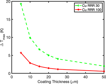
Figure 13. Maximum temperature growth in copper coated stainless-steel bellows in the LCLS-II cryomodule for different coating thicknesses for copper with RRR 30 (green) and RRR 100 (red). Note that copper with RRR of 100 possesses thermal conductivity of about 640 W/(m-K) at 4 K in comparison to 184 W/(m-K) of copper with RRR of 30 [50].
Download figure:
Standard image High-resolution image
The copper coating with RRR no less than 30 and thickness 15 μm has been specified for the cavity bellows in the LCLS-II cryomodule. The plating thickness is sufficient to deliver desired RF and thermal performances providing a few skin depths of copper to minimize RF losses on the bellows surface as well as to confine the maximum temperature growth within 10 K.
6. Summary
This paper described a comprehensive assessment of dynamic RF heating originating from operating fields, propagating wake-fields, trapped modes and resistive wall in a non-superconducting bellows assembly in vicinity of the superconducting cavities. Systematic studies presented here are applicable to any SRF cryomodule, providing a quick guidance to evaluate copper coating requirements for non-superconducting elements in SRF operation. In addition, these studies can be used to model a more relevant cryogenic heat load budget accounting for the bellows dynamic RF heating. The paper also reports a number of analytical expressions that can be used to understand the parameter dependences of complex RF heating mechanisms.
In this work calculations were made in framework of 1.3 GHz, CW, LCLS-II cryomodule for two types of the bellows surfaces i.e. copper and stainless-steel. It was found that a stainless-steel surface for the bellows assembly resulted in about four times higher heating (0.6 W) in comparison to the copper surface (0.15 W) at 2 K environment. The largest contribution to RF heating in the stainless-steel bellows assembly comes from broad-band propagating wake-fields that resulted in a total heating of 340 mW. However, the contribution was reduced to 60 mW for a copper coated bellows. Resulting RF heating causes temperature-rise at the bellows surface. It was reported that stainless-steel bellows attributes to relatively higher temperature growth of up to 72 K due to a poor thermal conductivity. Consequently, cavity-bellows in 1.3 GHz, CW, cryomodule of the LCLS-II linac features an inner copper coating of 15 μm over stainless-steel surface that facilitates to restricts its surface RF heating up to 0.15 W and the maximum temperature growth within 10 K. It can be concluded from studies that a copper coating is crucial to minimize and limit additional RF heating and temperature-rise at the bellows surface in a CW cryomodule for the high intensity electron beam acceleration. At the same time a pure stainless-steel bellows is an appropriate practical choice for a cryomodule in the hadron linac where wake losses are minimal because of relatively long bunch length and non-relativistic nature of the beam. This in turn allows to avoid stringent quality control required for a copper coated bellows in an SRF cryomodule due to potential flaking of the coating.
Acknowledgments
The authors would like to express gratitude to the large team of scientists, engineers and technical staffs who were involved in production of 1.3 GHz, LCLS-II cryomodule. On more personal level, authors would like to express gratitude to Yuriy Orlov for providing schematics of the LCLS-II cryomodule and Charles Grimm for having a useful discussion on Copper plating process. The authors are also thankful to Karl Bane and Martin Dohlus for useful discussions on wake-fields heating. The author also wishes to acknowledge efforts of Barbara Merrill and Dr. Priyanka Saini who proof-read this manuscript.
This manuscript has been authored by Fermi Research Alliance, LLC under Contract No. DE-AC02-07CH11359 with the US Department of Energy, Office of Science, Office of High Energy Physics.