
Abstract
This study proposes an alternative mass ratio definition for vortex-induced vibration (VIV) systems. The proposed definition, henceforth known as 'total mass ratio', differs from the conventionally used mass ratio definition (i.e. the ratio of the mass of the oscillating body to the mass of the displaced fluid) in that the added mass of the fluid is taken into account. Two-dimensional numerical simulations are conducted to compare the effect of mass ratio on the VIV response of two cylinders with different cross sections, namely, a fully-filled solid cylinder and a hollow cylinder with fluid-filled cavities; both are designed to generate identical flow characteristics. When plotted against the conventional mass ratio, VIV response amplitudes of the fully-filled and hollow cylinders are different despite the similarity in flow characteristics. Conversely, the trends of VIV response amplitude against total mass ratio for both cylinders overlap almost perfectly. Results therefore suggest that the total mass ratio definition yields a more complete representation of the mass property of the VIV system, especially when comparing cylinders of different cross-sectional geometries.
Export citation and abstract BibTeX RIS
1. Introduction
Vortex-induced vibration (VIV) is an extensively studied phenomenon that impacts many fields of engineering, including heat exchangers, civil engineering constructions, marine and offshore platforms, and more recently, energy harvesting. VIV is governed by dimensionless parameters that determine the systems' fluid, structural, and mass properties, including Reynolds number (Re), Strouhal number (St), velocity ratio (U*), mass ratio (m*), and structural damping ratio (ζ). Fundamental studies on VIV have been conducted throughout the past decades, primarily focusing on the VIV response of circular cylinders, many of which are discussed in recent reviews (Williamson 2004, Sarpkaya 2004).
In this study, we reconsider the conventional definition of mass ratio (m*) used in most VIV studies, which is the ratio of the mass of the oscillating body (i.e. mass of the solid body) to the mass of the displaced fluid. For fully-filled solid cylinders, this simplifies to the relative density between the solid and fluid, i.e. m* ≈ ρs /ρf , in which ρs and ρf are the densities of the solid and fluid, respectively. This conventional m* definition is widely used in recent studies involving the VIV of circular (Lupi et al 2018, Qin et al 2018, Shaaban and Mohany 2018, Soti et al 2018) and non-circular (Leontini et al 2018, Massai et al 2018) cylinders.
One key motivation of this research work is to address some observations noted in a recent VIV study (Lee et al 2019), in which the VIV response of a cylinder with a circular cross-section is compared to that of a cylinder with an 8-pointed isotoxal-star cross-section (henceforth referred to as 'star cylinder'). The VIV response of the circular cylinder was obtained at m* = 25 and damping ratio, ζ = 0.01, at structural natural frequency (fN ) equaled to the vortex shedding frequency (fv ) of a stationary circular cylinder. Because the study aimed to identify the effect of cross-sectional geometry on VIV response, an attempt was made to keep all parameters (i.e. mass and structural properties) constant during the comparison. Two approaches of maintaining constant mass property were considered; the first was to maintain constant m*, which was achieved by setting the density of the star cylinder to be identical to that of the circular cylinder. The second approach was to maintain constant cylinder mass, ms . The corresponding VIV response was quantified by the normalized maximum amplitude of oscillation, A*max = Amax/D, in which Amax is the maximum amplitude of oscillation and D is the cylinder diameter. The results from Lee et al (2019) indicate that maintaining constant ms yielded a more comparable VIV response between the two cylinders, whereas maintaining constant m* tended to create a star cylinder with very low mass and hence very high VIV response.
It is thus apparent that the conventional m* definition does not fully describe the mass property of the VIV system; rather, it describes only the mass property of the oscillating body without considering the influence of the surrounding fluid on the overall mass of the VIV system. It is interesting to note that several past studies (Griffin 1980, Skop and Balasubramanian 1997) have normalized the dynamical equation of VIV systems and arrived at a dimensionless parameter, μ, as shown in equation (1), in which ρf , ms , and ma are the fluid density, mass of the oscillating body and added mass (i.e. virtual mass), respectively. One important implication is that both the mass of the oscillating body and the added mass play an important role in determining VIV response. Hence, it can be said that in the context of mass property, the VIV system comprises of the oscillating solid body and a certain finite volume of the surrounding fluid that contributes to the added mass of the system. Although the μ definition in equation (1) may give a reasonable representation of the VIV system's mass property, a few issues may arise when attempting to use this quantity for conducting VIV studies: (i) St needs to be determined a priori, (ii) the ρf D2 term implies a cylinder with circular cross-section; whether it can be applied to an arbitrary cross-section is debatable, and (iii) unlike the simpler m*, the physical significance of μ is more difficult to discern.

Here, we propose a revised mass ratio definition that considers the mass of the oscillating body (ms
), the mass of the displaced fluid (md
), and the added mass (ma
). ms
refers to the mass of the oscillating body and any structural support components that move together during VIV. md
can be computed by multiplying the volume of the oscillating body that is submerged in the fluid by the fluid density. ma
is the added or virtual mass encountered by an accelerating body in the fluid due to the fact that a portion of the volume of the surrounding fluid must be accelerated alongside the solid body. The revised mass ratio definition is henceforth referred to as the 'total mass ratio',  defined in equation (2). Equation (2) can be expressed in non-dimensional terms, yielding equation (3), in which the added mass coefficient is given by Ca
= ma
/md
. The merits of this definition include: (i) ease of use because only mass values need to be determined a priori, (ii) applicable to arbitrary cylinder geometry, and (iii) the physical significance is clear;
defined in equation (2). Equation (2) can be expressed in non-dimensional terms, yielding equation (3), in which the added mass coefficient is given by Ca
= ma
/md
. The merits of this definition include: (i) ease of use because only mass values need to be determined a priori, (ii) applicable to arbitrary cylinder geometry, and (iii) the physical significance is clear;  is the mass of the VIV system normalized by the mass of the fluid that is displaced by the VIV system. Hence, for a neutrally buoyant solid body with ρs
= ρf
,
is the mass of the VIV system normalized by the mass of the fluid that is displaced by the VIV system. Hence, for a neutrally buoyant solid body with ρs
= ρf
,  = 1 is obtained.


Using two-dimensional (2D) numerical simulations, we will demonstrate that  offers a better collapse of VIV response data compared to m*. This is achieved by comparing the VIV response of two cylinders with different cross-section (see figure 1). The 'fully-filled cylinder' refers to a typical fully-filled solid cylinder, and the 'hollow cylinder' has a specially designed cross-section with four hollow cavities that are filled by the surrounding fluid. In the VIV simulations, both cylinders encounter steady cross-flow in the x-direction and undergo VIV in the y-direction.

Figure 1. Schematic drawings of the (a) fully-filled and (b) hollow cylinders in spring-mass-damper systems undergoing VIV.
Download figure:
Standard image High-resolution imageNote that the present study is a non-dimensional study that does not assume any dimensional values for quantities such as mass, natural frequency, fluid properties, flow velocity, and so forth. In the subsequent part of this report, all key parameters are expressed in non-dimensional terms only. Specifically, the fluid properties including the effects of fluid density and viscosity are represented by Reynolds number, Re = UD/ν, in which U and ν are the freestream velocity and fluid viscosity, respectively. Vortex shedding frequency (fv ) is represented by Strouhal number, St = fv D/U. For VIV cases, the relationship between U and the natural frequency (fN ) of the structure is important to determine if the system is in resonance; this relationship is represented by velocity ratio, U* = U/fN D. The oscillation frequency of the VIV system, f, is represented by the frequency ratio, f* = f/fN ; resonance is achieved when f* is near unity. The structural damping encountered by the VIV system is expressed as the damping ratio, ζ, which is related to the damping coefficient, mass, and structural stiffness of the VIV system; the exact definition of ζ will be given in section 2.2. Because of the non-dimensional nature of this study, the conclusions are valid for different fluid types including air and water.
2. Methodology
2.1. Numerical simulations
2D numerical simulations are conducted with ANSYS FLUENT, Release 16. The flow is assumed to be incompressible, transient, and laminar. The flow solver's spatial and temporal discretization schemes are second order accurate. The computational domain comprises of a cylinder (represented by non-slip walls) surrounded by a circular inner mesh with the diameter of 50D. This inner mesh comprises of structural quadrilateral elements and is surrounded by a rectangular outer mesh (100D width × 200D length) that comprises of unstructured triangular element (see figure 2). The boundary conditions of the outer mesh are: constant velocity inlet, zero gage pressure outlet, and symmetry/slip-wall sides.
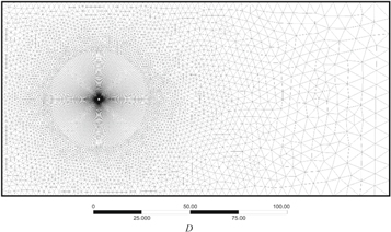
Figure 2. Mesh system used in the simulations.
Download figure:
Standard image High-resolution imageFlow over a stationary circular cylinder in steady cross-flow at Re = 150 is simulated to obtain grid convergence and time step size convergence. From the transient forces reported from the solver, lift coefficient (CL
) and drag coefficient (CD
) are computed based on equations (4) and (5). The stationary simulation is conducted for a duration of t = 150D/U, upon which the transient force trends have reached a periodic state, i.e. force generation from one cycle to the next differs by less than 0.5%. The duration of one vortex shedding cycle is determined by taking the time elapsed between two successive CL
peaks within the periodic state. In the same manner, vortex shedding frequency, fv
, can be obtained which yields St according to equation (6). Grid and time step size convergences are achieved at the mesh density of 33 thousand elements and a time step size of dt = 0.005D/U; this is evidenced by the fact that root-mean-square CL
fluctuation (CL
'), mean CD
( ), and St vary by less than 0.5% when the mesh density is doubled and the time step size is halved.


Using the converged grid and time step settings, VIV simulations are conducted in which the fully-filled and hollow cylinders are placed in steady cross-flow and allowed to oscillate as a spring-mass-damper system in the direction transverse to the cross-flow (see figure 1). The VIV dynamics are governed by equation (7), in which c, k, and Fy are the damping coefficient, spring stiffness, and fluid forces acting in the transverse direction, respectively.

In the VIV simulations, a dynamic mesh approach is adopted in which the unstructured outer mesh undergoes spring-like deformation; conversely, the structured inner mesh moves as a rigid body without mesh deformation, which helps to preserve the near-field mesh quality. During each simulation time step, mesh motion is implemented according to the algorithm shown in figure 3(a). An under-relaxation factor, α, is introduced in the mesh velocity computation to ensure numerical stability. Generally, α = 0.5 is implemented except for cases with very low  < 1.5, for which under-relaxation as low as α = 0.02 is used to ensure stability and convergence. Validation is conducted against past results (Leontini et al
2006) by simulating a fully-filled circular cylinder in VIV at Re = 150, m* = 10 and damping ratio, ζ = 0.01. The validation results, depicted in figures 3(b) and (c), show good agreement in terms of both amplitude response (A*max) and frequency response (f*).
< 1.5, for which under-relaxation as low as α = 0.02 is used to ensure stability and convergence. Validation is conducted against past results (Leontini et al
2006) by simulating a fully-filled circular cylinder in VIV at Re = 150, m* = 10 and damping ratio, ζ = 0.01. The validation results, depicted in figures 3(b) and (c), show good agreement in terms of both amplitude response (A*max) and frequency response (f*).

Figure 3. (a) The VIV simulation algorithm, and the validation results of present VIV simulation method by comparing the (b) A*max and (c) f* obtained using the present method against those reported in Leontini et al (2006). Validation case parameters are: Re = 150, m* = 10 and damping ratio, ζ = 0.01.
Download figure:
Standard image High-resolution image2.2. Approach and parameter selection
In this study, all tests are conducted at a relatively low Re = 150, which ensures that the flow remains below the critical Re for 2D-to-3D transition (see Jiang et al 2017, among others), and thus conferring validity to our 2D simulation framework. The study is conducted in three stages, which are detailed as follows.
In the first stage, the flow behaviors over both the fully-filled cylinder and the hollow cylinder are investigated under stationary conditions to confirm that they are almost identical. Transient CL
and CD
computed from these simulations are shown in figure 4(a), indicating close agreement once periodic flow is achieved after tU/D = 120. Quantitative analysis shows that CL
',  and St are 0.363, 1.315, and 0.184, respectively, for the fully-filled cylinder; the corresponding values are 0.354, 1.302, and 0.184, respectively, for the hollow cylinder. Based on the small difference in these quantities (<2.5%), we can assume that the two cross-sections yield almost identical flow behavior. From this, it is reasonable to postulate that, if all the VIV parameters are properly defined and maintained constant, the two cylinders should yield almost identical VIV response.

Figure 4. (a) Force coefficients from stationary fully-filled and hollow cylinders in cross-flow, and (b) velocity profile and transient drag coefficient of cylinders undergoing accelerating motion, used to compute added mass.
Download figure:
Standard image High-resolution imageIn the second stage, additional simulations are conducted to quantify ma
for both the fully-filled and hollow cylinders, which are required to compute  This is achieved by comparing the drag forces of the cylinders under acceleration and under constant speed conditions. In the second stage simulations, both cylinders are given a transient velocity profile (u) which increases linearly from 0 to U (corresponding to UD/ν = Re = 150); the velocity profile is shown in figure 4(b). When accelerating, the cylinders encounter an additional added mass force, Fa
, which is given in equation (8). When the acceleration stops abruptly, Fa
decreases immediately to zero, which manifests as a rapid drop in CD
as depicted in figure 4(b). Hence, from the drop in CD
and equation (8), ma
can be quantified. This method of obtaining added mass is conceptually similar to past added mass studies (Wakaba and Balachandar 2007). From the simulation results shown in figure 4(b), we obtain Ca
= 1.02 and 3.68 for the fully-filled and hollow cylinders, respectively. Ca
of the hollow cylinder deviates notably from that of the fully-filled cylinder because of very high added mass (ma
), due to the presence of fluid in the hollow cavities that accelerate with the cylinder, and low displaced mass (md
), due to the lower overall solid volume of the cylinder.
This is achieved by comparing the drag forces of the cylinders under acceleration and under constant speed conditions. In the second stage simulations, both cylinders are given a transient velocity profile (u) which increases linearly from 0 to U (corresponding to UD/ν = Re = 150); the velocity profile is shown in figure 4(b). When accelerating, the cylinders encounter an additional added mass force, Fa
, which is given in equation (8). When the acceleration stops abruptly, Fa
decreases immediately to zero, which manifests as a rapid drop in CD
as depicted in figure 4(b). Hence, from the drop in CD
and equation (8), ma
can be quantified. This method of obtaining added mass is conceptually similar to past added mass studies (Wakaba and Balachandar 2007). From the simulation results shown in figure 4(b), we obtain Ca
= 1.02 and 3.68 for the fully-filled and hollow cylinders, respectively. Ca
of the hollow cylinder deviates notably from that of the fully-filled cylinder because of very high added mass (ma
), due to the presence of fluid in the hollow cavities that accelerate with the cylinder, and low displaced mass (md
), due to the lower overall solid volume of the cylinder.

The third stage comprises of three series of VIV simulations. Based on the information from the first two stages, the parameters for these VIV simulations are defined. In all cases, the natural frequency of the oscillating system (fN ) is set to the vortex shedding frequency (fv ) obtained from the stationary cylinder simulation, effectively setting the velocity ratio, U* = 1/St. For the present scenario, St = 0.184 obtained from the first stage of the study results in U* = 5.4. The spring stiffness (k) and damping coefficient (c) are computed from equations (9) and (10), respectively, in which the damping ratio (ζ) for all VIV scenarios are set to ζ = 0.1.


The parameters of the three VIV simulation series are detailed as follows. Series 1 investigates the VIV response of the fully-filled cylinder at m* = 1.0, 2.0, 5.0, 10.0, and 20.0, which correspond to the  range of 1.0, 1.5, 3.0, 5.5, and 10.4 according to equation (3). Series 2 investigates the VIV response of the hollow cylinder at m* = 1.0, 2.0, 5.0, 10.0, and 20.0; which are identical to the m* values in Series 1. Conversely, Series 3 investigates the VIV response of the hollow cylinder at
  = 1.0, 1.5, 3.0, 5.5, and 10.4; matching the
  range of Series 1. The m* and
  parameters used for the three series of tests are summarised in table 1. VIV response amplitude of all three series will be plotted against m* and
  Whether m* or
  is more representative of the mass property of the VIV system will become obvious from these plots. VIV simulations are conducted for a duration of tU/D = 200, upon which periodic or quasi-periodic motion is observed for all cases. The normalized maximum amplitude of oscillation, A*max, is sampled from the periodic or quasi-periodic part of the motion (hereby assumed tU/D = 150 to 200).
Table 1. Parameters for VIV simulations series. All cases have Re = 150, ζ = 0.1, and U* = 5.4.
| Cross-section | m* |

| |
|---|---|---|---|
| Series 1 | Fully-filled cylinder | 1.0, 2.0, 5.0, 10.0, 20.0 | 1.0, 1.5, 3.0, 5.5, 10.4 |
| Series 2 | Hollow cylinder | 1.0, 2.0, 5.0, 10.0, 20.0 | 1.0, 1.2, 1.9, 2.9, 5.1 |
| Series 3 | Hollow cylinder | 1.0, 3.3, 10.3, 21.9, 45.1 | 1.0, 1.5, 3.0, 5.5, 10.4 |
3. Results
Selected transient VIV displacement profiles from Series 1 and 2 simulations are depicted in figures 5(a) and (b), respectively. In terms of frequency response, f* for all of the simulated cases fall within a narrow range of 1.02 < f* < 1.07; the values of f* near unity indicate that the system is in resonance, which is in line with our initial assumption. However, the transient times and the amplitudes of oscillations are different for the two series of cylinders. Series 2 reach periodic state (tU/D ≲ 100) faster than Series 1 (tU/D ≳ 100). As for the amplitudes, those of Series 2 are larger than those of Series 1. Both of these trends indicate that adopting m* as the governing parameter will overestimate the overall mass of the oscillating hollow cylinders, especially for large values of m*.

Figure 5. Transient VIV response of (a) the fully-filled cylinders from Series 1 and (b) the hollow cylinders from Series 2. Also shown is the A*max of each Series plotted against (c) m* and (d) 
Download figure:
Standard image High-resolution image
Figures 5(c) and (d) show the maximum VIV response amplitude plotted as a function of m* and  respectively. In figure 5(c), the A* of Series 2 and 3 are higher than the A* of Series 1 due to the added mass effect. From a different perspective, for a given magnitude of A*, the m* of Series 2 and Series 3 are larger than that of Series 1, which support the above observation that m* overestimate the overall mass if the cross-sectional shape is not a fully-filled cylinder. In figure 5(d), the curves shift toward the left-hand side when the added mass effect is considered in the
  With the Series 2 and 3 shift more than Series 1, the three series collapse into a single curve. The collapse of the three series in figure 5(d), as compared to the discrepancies in figure 5(c), strongly supports our initial postulation that
  is a more appropriate representation of the mass property of VIV systems, especially when the cross-sectional geometry is not fully-filled cylindrical shape.
4. Conclusion
An alternative definition for the mass ratio of VIV systems have been proposed and tested, with the aim of establishing a means of quantifying mass property consistently for VIV systems, especially between those with different cross-sectional geometry. The proposed 'total mass ratio' ( ) differs from the widely used mass ratio (m*) definition in that added mass of the fluid is considered.
2D numerical simulations have been conducted to demonstrate the merits of this  definition. The VIV response of a fully-filled solid circular cylinder is compared to that of a modified hollow cylinder with fluid-filled cavities. Preliminary simulations have shown that both cylinders generate almost identical flow structure and fluid forces. When the amplitudes of VIV response of both cylinders are plotted against m* and
  , it is apparent that the
  definition yields better collapse. Conversely, m* does not give a good representative of the mass property of the hollow cylinder. Results imply that the mass property of VIV systems should consider the added mass contributed by the surrounding fluid. Results strongly suggest that, for studies investigating the VIV response of bluff bodies with different geometry, the
  definition proposed here is more representative of the mass property of the VIV system.
Acknowledgments
This work was supported by the Ministry of Education, Singapore Academic Research Fund (AcRF) FRC Tier 1 Grant (R-265-000-585-114).