
Abstract
In this paper, the microstructure and mechanical properties of dissimilar welding of AISI 304 L austenitic stainless steel and UNS C70600 copper-nickel alloy have been investigated. For this purpose, Tungsten-Gas Arc welding method with both pulse and non-pulse currenst and ERNiCr-3 welding wire was applied. The microstructures of different regions were evaluated using optical microscope and scanning electron microscope. The result showed that ERNiCr-3 filler metal has fully austenitic microstructure in both pulse and non-pulse modes, but in pulse mode, dendrites were found to be smaller than non-pulse mode. In both interfaces, between base and weld metal, partially melting zone was illustrated. Increasing grain size was more intense in the HAZ region of the copper-nickel base metal. In the tensile test, all samples were ruptured from the HAZ region of copper-nickel alloy with ductile fracture mode. According to the result of tensile test, tensile strength of the welded sample in pulse and non-pulse modes was 235 MPa and 268 MPa, respectively. The results of the hardness test showed that the hardness of the weld region in the pulse mode (75.3HRB) was slightly higher than hardness in non-pulse mode (71.6HBR). Minimum hardness number (17HRB) was related to the UNS C70600 alloy.
Export citation and abstract BibTeX RIS
1. Introduction
AISI 304L austenitic stainless steel and UNS C70600 copper-nickel alloy is widely used in industry. The main difference between the UNS C70600 copper-nickel alloy and 304L austenitic stainless steel is the higher corrosion resistance of this alloy, especially in marine environments. Chlorine in seawater causes pitting-corrosion in stainless steels. A characteristic feature of 304L steel is its low carbon content, which reduces the susceptibility to carbide deposition when welding [1]. Welded C70600 copper-nickel alloy has excellent resistance to high temperature oxidation, stress corrosion cracking (SCC) and corrosion of seawater. For decades, thousands of tons of these alloys have been used to make seawater tubes, shipbuilding, power industry and desalination industry. The elements such as magnesium, niobium, iron and chromium in this alloy create a good mix of mechanical and corrosion properties [2].
In many power industries such as bioenergy factories, fossil or nuclear facilities, as well as in food production facilities, the dissimilar joint of ferrous and non-ferrous metals is important [3]. The dissimilar joint of stainless steel and other steels is often used in cases that require mechanical properties [4]. One of the suitable methods to decrease the inappropriate effects of dissimilar welding such as carbon migration, formation of undesired phases in the interface, formation of residual stresses as a result of the difference in the coefficient of heat transfer of the base metals, occurrence of electrochemical corrosion at the welding area [5], is the use of welding with pulse current. In pulsed current gas tungsten arc welding (PCGTAW), the flow of welding changes periodically from low to high at a regular frequency. PCGTAW can be used at low frequencies (1–10 Hz) or very high frequencies (above 5000 Hz) and it causes lower heat input than gas tungsten arc welding with constant current and other conventional melting methods [6, 7].
Shayanfar et al have been investigated dissimilar welding of quench-tempered ASTM A517 steel to AISI316L stainless steel and the effect of welding parameters on microstructure [8]. The results showed that due to lower heat input in pulsed method, the grain size of the heat affected zone as well as the grain size of the welding area in the pulsed method was lower than the conventional method. The results showed that improvement of microstructure improves mechanical properties and impact energy in pulse welding. This increase reflects the fact that by decreasing the diameter of the grains in the pulsed method and therefore, increasing the boundaries, the yield stress and finally, the resistance of the samples in the pulsed welding method has increased. Kangasian et al have been investigated optimization of tungsten-gas welding parameters by pulsed method in dissimilar welding of AISI 304 stainless steel to St 52 steel [9]. Optimization of welding parameters was performed by Taguchi method in order to find optimal amount of microhardness and corrosion potential (Ecorr). The results showed that the frequency had the highest effect (82.43%) on the improvement of microhardness and Ecorr of the welding metal, while the base current (Ib) had a lower effect (16.47%) and pulse current (Ip) was less important than the other two parameters. In other investigations, to improve the properties of the joints, various welding methods, heat treatment after welding and the variation of welding parameters has been studied [10, 11]. In many industrial applications, there is no possibility of using special welding methods such as laser and solid state welding, and also the heat treatment after welding is used in special conditions; but the use of pulse welding method is a practical way to improve the properties of the joints. The dissimilar welding of 304 L austenitic stainless steel and UNS C70600 copper-nickel alloy is important in various industries, especially in the construction, marine structures and salt-containing industries, adequate research is needed. In this research, the effect of gas tungsten arc welding method with pulse current on microstructure and mechanical properties of dissimilar welding of 304 L austenitic stainless steel and UNS C70600 copper-nickel alloy and the comparison with constant current welding conditions has been investigated.
2. Experimental method
In this study, the UNS C70600 copper-nickel alloy and 304 L austenitic stainless steel pipes with dimensions of 152.4 × 3.4 mm were used for welding. Cutting of samples was performed by a plasma machine and edge preparation was done by a grinding machine. The join area was degreased by steam. Welding was performed with single V groove butt Joint design, 37.5° bevel angle, 2 mm of depth and 3 mm of gap spacing and without preheating. Preparation of samples was done according to API RP 582 standard and also, according to the thickness of base metals [12]. The welding process was performed using tungsten-gas arc welding procedure with the pulsed and non-pulsed methods and negative electrode polarity at 5 G situation and in 3 passes. Non-pulsed welding was carried out manually with the Pars-EL631 device. The pulsed welding was done with TIG-200P Iran-trans device at Shahreza Azad University. Electrodes used in the pulsed and non-pulsed processes were tungsten electrodes containing 2% thorium oxide with 2.4 mm diameter. The consumable electrode was ERNiCr-3 electrode with 2.4 mm diameter, which was selected according to ASME SFA A5.14 standard [13]. The chemical analysis of base metals and filler metals is presented in table 1.
Table 1. Chemical composition of the base metals and weld metal.
| Elements | Fe | Mo | Ni | Cr | S | P | Mn | Si | C | Cu |
|---|---|---|---|---|---|---|---|---|---|---|
| UNS C70600 | 1.1 | 1.80 | 9.1 | 0.01 | 0.012 | 0.01 | 1.80 | 0.027 | 0.02 | Bal. |
| SS 304 L | Bal. | 1.22 | 10.1 | 18.71 | 0.047 | 0.027 | 1.64 | 0.22 | 0.017 | 0.4 |
| ERNiCr-3 | 3 | 3 | Bal. | 16.56 | 0.02 | 0.02 | 0.5 | 0.75 | 0.1 | 0.5 |
Argon gas with purity of 99/99% with a flow rate of 15 liters per minute in first pass and 10 liters per minute in subsequent passes, was used as a protective gas. Also, the argon protective gas with the same flow rate as the back gas was used to prevent the oxidation of root pass. Interpass temperature was considered 175 °C to reduce the stresses due to the contraction and cooling of the welding metal. The welding parameters in the pulsed and non-pulsed states are presented in tables 2 and 3. The amount of heat input was calculated according to the following equation:

Where  is the welding current (A),
  is the welding voltage (v),
  is the welding speed (mm sec−1) and
  is the welding efficiency that was considered 0.6 for Tungsten-Gas welding. In addition, the flow rate and frequency in the pulsed welding mode was calculated according to the following equations:


Where  is pulse current (A),
  is time of pulse current (sec−3),
  is base current and
  is time of base current.
  is average current or start current [14].
Table 2. Welding parameters in the pulsed mode.
| Pass number | Pulse current (A) | Base current (A) | Voltage (V) | Frequency (Hz) | Welding speed (mm sec−1) | Heat input (Kj mm−1) |
|---|---|---|---|---|---|---|
| 1 | 120 | 50 | 11 | 4 | 1.08 | 3.299 |
| 2 | 130 | 60 | 12 | 6 | 1.1 | |
| 2 | 130 | 70 | 13 | 7 | 1.2 |
Table 3. Welding parameters in the non-pulsed mode.
| Pass number | current (A) | Voltage (V) | Welding speed (mm sec−1) | Heat input (Kj mm−1) |
|---|---|---|---|---|
| 1 | 130 | 12 | 1.07 | 3.370 |
| 2 | 140 | 10 | 1.1 | |
| 2 | 150 | 11 | 1.1 |
To investigate the microstructure, after welding, specimens with dimensions of 6 × 15 × 30 mm were prepared for metallographic experiments from the different parts of the weldments. The surfaces were polished by 80 to 3000 silicon carbide paper and final polishing was performed with 0.3 mm solution containing alumina powder. After polishing, nickel-copper alloy components for 30 s, 304L stainless steel components for 1.5 minutes, and ERNiCr-3 weld metals for 4 min, were etched with Marble solution, then the investigations were performed with optical and electron scanning microscope.
Preparing samples for tensile test was performed according to ASTM A370 standard [15]. The tensile speed was 5 mm min−1 and the length of the gauge was 70 mm. Micro-hardness test was performed using B Rockwell method according to ASTM E384 standard [16]. The applied force was considered 100 gr and the applied time of force was considered 10–15 s.
3. Results and discussion
3.1. Microstructure
Optical microscope images for base metals have been shown in figure 1. As can be seen microstructure of copper-nickel alloy (figure 1(a)) consists of single-phase grains of α with different orientations in the structure. The existence of α phase is explainable due to the complete solution of copper and nickel in the each other. This is due to the similar atomic radius and the network parameter of nickel and copper atoms. At all temperatures, copper-nickel alloys have a single-phase FCC structure [17]. Microstructure of austenitic stainless steel (figure 1(b)) shows a completely austenitic structure. Also, there is amount of ferrite phase in this type of steels. The ferrite in the grain boundary is caused by the separation of ferrite creator elements, especially chromium during solidification [4].

Figure 1. Optical microscope images of (a) UNS C70600 base metal microstructure, (b) 304L base metal microstructure.
Download figure:
Standard image High-resolution imageThe optical microscope microstructure of ERNiCr-3 weld metal in two welding modes with pulsed and non-pulsed current is shown in figure 2. In non-pulse mode (figure 2(a)), the microstructure consists of fully austenitic phase with dendrite structure. The nickel element in the ERNiCr-3 weld metal stabilized the austenite phase. This solidification is (A) type (single-phase austenite) solidification mode. This type of solidification is due to the separation of alloying elements and impurities during solidification. Within the grains, the dendritic cellular structure, is dominant structure. Another phenomenon that can be seen in microstructure is Solidification Grain Boundary (SGB) and Migration Grain Boundary (MGB), which are characterized on figure 2. However, there is also a different kind of grain boundary called Solidification Sub-Grain Boundary (SSGB), which has more difficult detection and is not well visible in the microstructure [18].
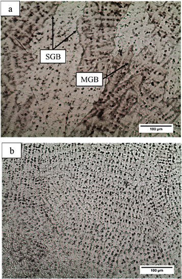
Figure 2. Optical microscope images of ERNiCr-3 weld metal microstructure (a) non-pulsed mode (b) pulsed mode.
Download figure:
Standard image High-resolution imageIn pulse mode (figure 2(b)), the dendrites is much smaller than the non-pulsed mode, and the solidification grain boundaries are closer to each other. The reason is lower heat input in pulse mode, which causes formation of smaller dendrites in the microstructure. In fact, when the lower heat input is applied to the weld metal, the dendrites and the solidification grain boundary have less time to grow. In the weld metal structure, amount of ferrite is observed due to Cr element segregation during solidification. δ ferrite can also be a preferred location for the sigma phase formation. The absence of δ ferrite can lead to formation of hot cracks [19]. Nb presence in filler increases solidification range and changes the structure from dendritic cellular to columnar [20].
Pulse welding reduces the size of dendrites compared to non-pulse welding and the grain boundaries are closer together due to the lower heat input [21]. The lower heat input restricts growth of austenite in HAZ region of SS 304L.
In order to investigate the probability of carbide particles precipitation, the electron microscope images of ERNiCr-3 weld metal have been shown in pulse mode in two different magnifications, as shown in figure 3. It can be seen that the white points are visible in the microstructure shown by the arrow mark. According to the images of Back-Scattered Electron (BSE), it can be said that this points is carbides which contains heavy elements. Hajiahia et al [22] have been reported these particles are the niobium carbides that are distributed homogeneously in the microstructure. These carbides are mostly formed on solidification grain boundary and cause the boundaries to be locked up at high temperatures. This action creates curved boundaries in this weld metal. Curved boundaries decreases the possibility of Ductility Dip Cracking (DDC) in this weld metal. DDC is formed on grains boundary due to rejection of impurities in these areas [18]. W and Nb carbides lock the boundaries and increase strength via pinning [23].

Figure 3. Electron microscope microstructure of ERNiCr-3 weld metal in the pulsed mode.
Download figure:
Standard image High-resolution imageThe interface between the base metal of austenitic stainless steel and welding metal in non-pulse and pulse modes has been shown in figures 4(a) and (b), respectively. As can be seen, austenitic stainless steel grains in the heat affected zone (HAZ) are smaller in pulse mode than non-pulse and have a better distribution.
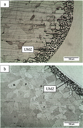
Figure 4. Optical microscope images of the 304L base metal and ERNiCr-3 weld metal interface (a) non-pulsed mode (b) pulsed mode.
Download figure:
Standard image High-resolution imageThis will improve the mechanical properties of the weld metal in this area. The HAZ zone in fusion welding is one of the most sensitive parts of the weldments. If given no special attention, there is a possibility of some defects such as cracking or reducing mechanical properties in this area. The lower amount of heat input leads to the lower thickness of HAZ area, and therefore, the welding component will have better mechanical properties. As mentioned, pulse welding would reduce the heat input and, as a result, would have a better microstructure in the HAZ region in the pulsed state. Another phenomenon observed in this interface is the Partially Melted Zone (PMZ). The dark phases observed in PMZ regions in figure 4 are ferrite phases. In this area, the ferrite phase is much more than other regions of the 304L austenitic base metal. The reason is that in the PMZ region, during solidification, ferrites are initially formed, but since the heat transfer rate is very high, there is not enough time to convert ferrite to austenite, and therefore, the ferrite percentage will be higher than austenite. By comparing the microstructure of the pulsed and non-pulsed mode interface, it is observed that in pulse mode, the thickness of the PMZ region is less than non-pulse mode due to the low heat input in pulse mode. This also improves the properties in pulse mode.
Figures 5(a) and (b) illustrate the optical microscope images of UNS C70600 copper-nickel alloy base metal and ERNiCr-3 weld metal interface in non-pulse and pulse mode, respectively. It can be observed that the PMZ region in this interface is larger than that of the 304L base metal and the weld metal because of the higher heat transfer coefficient of the UNS C70600 alloy than the 304L steel. The heat transfer coefficient of 304L steel is about 17 W mK−1, while the value for the UNS C70600 alloy is about 40 W/m.K. The higher heat transfer coefficient increases the heat transfer from the fusion boundary to the base metal. Since the melting temperature of the UNS C70600 alloy (1170 °C) is less than that of the 304L steel (1400 °C), the more area of the UNS C70600 alloy melts, and as a result, thickness of the PMZ region increases [24].
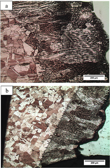
Figure 5. Optical microscope images of the UNS C70600 base metal and ERNiCr-3 weld metal interface (a) the non-pulsed mode (b) the pulsed mode.
Download figure:
Standard image High-resolution image3.2. Mechanical properties
The results of the tensile test are given in table 4. Strength in pulse mode (265 MPa) is more than non-pulse mode (235 MPa). The reason for this is the low heat input, and so, better microstructure in pulse mode that causes higher tensile strength. During the test, it was observed that the plastic deformation starts at HAZ area of the UNS C70600 base metal and continues to the base metal because of softness of copper-nickel base metal, especially in the HAZ area. The HAZ area of copper-nickel base metal contains larger grains than the base metal, and in addition, the PMZ area is located in this HAZ zone and has more soften structure. In both pulsed and non-pulsed samples, rupture occurred in the copper-nickel base metal. Also, the high amount of elongation was related to copper-nickel base metal.
Table 4. Tensile test results.
| Type of current | Yield strength (MPa) | Tensile strength (MPa) | Elongation (mm) | Failure location |
|---|---|---|---|---|
| Non-pulsed | 50 | 235 | 0.31 | UNS C70600 base metal |
| Pulsed | 50 | 265 | 0.35 | UNS C70600 base metal |
The result of hardness test for non-pulse and pulsed welding samples has been shown in figures 6(a) and (b), respectively. The change in the hardness of the weld metal in pulse mode is slightly more than the change in hardness in non-pulse mode. The average hardness of the weld metal in pulse and non-pulse mode is 75.3 and 71.6 HRB, respectively, which is justified by microstructural changes. In pulse mode, the heat input is lower and, as a result, during solidification, the size of the created dendrites is smaller than non-pulse mode. In fact, in pulse mode, there was not enough time to grow more dendrites. In the case of the copper-nickel alloy base metal, as observed, the lowest hardness in weldment was related to this base metal. In addition, the hardness is almost the same in both pulsed and non-pulsed modes (about 17 HBR), but in the HAZ region, increasing the hardness can be observed because of the PMZ region, which has dendritic structure, and so has higher hardness than other parts. Also, decreasing the hardness of the region after PMZ in non-pulse mode due to the presence of coarser grains in this area was observed in microstructural studies. The inside of the grain is softer than the grain boundary and, therefore, has less hardness. The presence of finer grains in the HAZ region in pulse mode caused that hardness of this area did not decrease. In base metal of 304L, hardness decreased in in the HAZ region in both pulse and non-pulse modes due to the higher percentage of ferrite in this region.

Figure 6. Hardness test results using Rockwell B (a) the non-pulsed mode (b) the pulsed mode.
Download figure:
Standard image High-resolution image
4. Conclusion
From the current study the following results were obtained:
- (1)The base metal microstructure of The UNS C70600 copper-nickel alloy comprises a single α phase with the different orientations. Also, the 304L austenitic stainless steel has a complete austenitic microstructure.
- (2)The ERNiCr-3 weld metal has a dendritic and fully austenitic microstructure and the solidification mode was single-phase austenite (A) mode.
- (3)In the pulsed welding mode, the dendrites are much smaller than those of the non-pulsed mode, and the solidification grain boundaries are closer to each other.
- (4)The thickness of PMZ region at the interface of copper-nickel alloy with weld metal was higher than that of the interface of stainless steel with weld metal and has a dendritic structure.
- (5)Grains in the HAZ region of the non-pulsed mode were larger than that of the pulsed mode.
- (6)The results of the tensile test showed that the tensile strength in the pulsed mode (265 MPa) is more than the non-pulsed mode (235 MPa).
- (7)The change in the hardness of the weld metal in the pulsed mode (75.3 HBR) is slightly more than the non-pulsed mode (71.6 HBR). The lowest hardness was reported for the UNS C70600 alloy (17 HBR). In addition, the PMZ region in the UNS C70600 alloy had a higher hardness than the other parts of the alloy.