
Highlights
Molecular dynamics simulation of double-grits interacted grinding of GaN crystals is performed.
Interacted distance with both radial and transverse directions is better than that with only one direction or single-grit grinding.
Girt-interactions decrease force, friction coefficient, stress, damage depth, and abrasive wear.
Amorphous, phase transition, dislocation, stacking fault and lattice distortion dominate plastic damage.
Abstract
Elucidating the complex interactions between the work material and abrasives during grinding of gallium nitride (GaN) single crystals is an active and challenging research area. In this study, molecular dynamics simulations were performed on double-grits interacted grinding of GaN crystals; and the grinding force, coefficient of friction, stress distribution, plastic damage behaviors, and abrasive damage were systematically investigated. The results demonstrated that the interacted distance in both radial and transverse directions achieved better grinding quality than that in only one direction. The grinding force, grinding induced stress, subsurface damage depth, and abrasive wear increase as the transverse interacted distance increases. However, there was no clear correlation between the interaction distance and the number of atoms in the phase transition and dislocation length. Appropriate interacted distances between abrasives can decrease grinding force, coefficient of friction, grinding induced stress, subsurface damage depth, and abrasive wear during the grinding process. The results of grinding tests combined with cross-sectional transmission electron micrographs validated the simulated damage results, i.e. amorphous atoms, high-pressure phase transition, dislocations, stacking faults, and lattice distortions. The results of this study will deepen our understanding of damage accumulation and material removal resulting from coupling between abrasives during grinding and can be used to develop a feasible approach to the wheel design of ordered abrasives.
Export citation and abstract BibTeX RIS

Original content from this work may be used under the terms of the Creative Commons Attribution 4.0 license. Any further distribution of this work must maintain attribution to the author(s) and the title of the work, journal citation and DOI.
1. Introduction
The gallium nitride (GaN) single crystal is the semiconductor with the highest application potential for manufacturing chip wafers due to the large bandwidth, high breakdown voltage, high electron mobility, and stable chemical and physical properties under extreme conditions [1–3]. To fabricate thin chip wafers, bulk GaN crystals must be processed using a sequence of machining methods, including wire saw cutting, grinding, lapping, and polishing. Large chip wafers cannot be machined by lapping and are mainly machined by wire saw cutting, self-rotating grinding, and polishing. Self-rotating grinding can achieve the highest material removal and accurately control the surface shape and thickness of wafers. Self-rotating grinding has thus become necessary for backthinning of chip wafers. However, brittle fractures or micro cracks induced during grinding process can severely deteriorate the application accuracy and service life of crystal components [4–6]. Therefore, numerous researchers focused on conducting polishing [7–10] and high-energy beam etching [11, 12] of GaN semiconductors to eliminate the brittle damages of components. Kubota and Iwakiri [7] carried out a tribochemical reaction to polish GaN substrates, producing a smooth surface with a root-mean-square roughness of 0.133 nm. The tribochemical reaction produced an oxide layer on the substrate surface, enabling removal of the work material under low stress. Pan et al [8, 9] performed chemical–mechanical polishing (CMP) tests on GaN semiconductors in conjunction with the electro-Fenton process to promote material removal. Zhang et al polished GaN wafers using plasma [11] and electrochemical [12] etching. The wafer surface had subnanometer-scale roughness, and materials were removed at the atomic scale. Although plastic surface free of surface and subsurface cracks was achieved using CMP or high-energy beam etching technologies, the low material removal efficiency of polishing and etching has hindered the large-scale industrial production and application of GaN chips [13–16].
The material removal efficiency of grinding is 105–107 times that of polishing, and plastic removal produces a considerably lower surface roughness and damage depth than brittle removal. Ductile grinding of hard and brittle crystals could effectively improve the surface quality and reduce the subsurface damage depth, thereby reducing the time required for subsequent polishing. Therefore, considerable effort has been expended to achieve ductile grinding of hard and brittle crystals [17–22], to improve the processing efficiency by ensuring the surface integrity of the crystal components. Shamray et al [23] investigated the ductile-to-brittle transition behaviors of Si3N4 ceramics, and a Si3N4 substrate with a ductile surface and subsurface was obtained by controlling the maximum undeformed chip thickness. Yang et al [24] investigated the ductile removal phenomenon of 3C-SiC involved in precision grinding process. Electrolytic in-process dressing was found to facilitate the generation of a compressive residual stress, enabling ductile removal of 3C-SiC. Wang et al [25] analyzed how the removal mode affected the acoustic emission (AE) and force during grinding of sapphire. The depth of the ductile-to-brittle transition region could be monitored using the AE data and force curves.
Material removal of semiconductors by grinding occurs largely through mechanical action and to a small extent through the tribochemical reaction. Therefore, the ductile grinding mechanism, i.e. the characteristics of ductile deformation and removal of work materials during grinding, needs to be elucidated to optimize process parameters to achieve high-efficiency and high surface integrity machining of hard and brittle materials [26–29]. Tao et al [30] carried out scratching tests and transmission electron microscopy (TEM) to elucidate the mechanism of ductile damage in silicon wafers. This mechanism was found to facilitate high-efficiency production of high-efficiency production of large-size silicon wafers. Li et al [31] revealed the ductile grinding mechanism of silicon substrates using single-grit scratching tests and smoothed-particle-hydrodynamics simulations, and they concluded that the understanding of ductile mechanism would provide theoretical guidance for optimizing grinding parameters. Wang et al [32] used single-grit impact scratching tests to explore the ductile grinding mechanism of β-Ga2O3. This mechanism was found to facilitate high-efficiency grinding of brittle materials. Single-grit scratch tests were performed in conjunction with cross-sectional TEM to investigate the plastic deformation of monocrystalline GaN induced during grinding. The main forms of plastic deformation were a high-pressure phase transition, an amorphous transition, stacking faults, dislocations, nanocrystals, and lattice distortions [33–35]. However, as a result of the random distribution of abrasives and complex interactions between the work material and abrasives [36–39], the effect of coupling between randomly located abrasives on damage accumulation and material removal during grinding of GaN single crystals remains unclear.
Ultra-precision grinding experiments cannot quantitatively characterize the influence of coupling actions between abrasive particles on damage accumulation and material removal [40, 41]. High-speed scratching experiments at the nanoscale cannot accurately control the machining depth and measure the high-frequency scratching force exerted by abrasives. Therefore, researchers have performed molecular dynamics (MD) simulations on double- and multiple-grits grinding to investigate grinding-induced damage accumulation and material removal [42–48]. Meng et al [42] used MD method to investigate the coupling between abrasives on material removal behavior during double-grits grinding of 6H-SiC crystals. The coupling among multiple abrasives during machining helped improve the surface smoothness and decrease subsurface damages. Guo et al [43] performed MD simulations of multiple-grits grinding of monocrystalline silicon, and they found that multiple-grits grinding effectively decreased the thickness of the damage layer induced by the single-grit grinding. Zhou et al [44] used MD method to simulate material removal process involved in multi-abrasives machining of SiC substrates. The distribution and exposed height of the abrasives strongly affected the machining temperature and subsurface damage. Zhao et al [45] studied how the superposition of abrasives affected the surface generated during double-grit grinding of monocrystalline silicon. The superposition of abrasives was found to reduce the tangential force and temperature but increase the residual stress. Hu et al [46] performed MD simulations to investigate the coupling between double grits during vibration-assisted grinding of single-crystal SiC, and defined an overlap ratio to describe the coupling degree between double grits. The MD results showed that the coupling degree of the abrasives increased with the overlap ratio, substantially improving the machining efficiency and surface integrity. MD simulations can reproduce transient removal characteristics during chip grinding, which is difficult to capture in a grinding experiment, and quantitatively analyze the damage accumulation and material removal behaviors induced by abrasive machining [49–51]. These simulations can elucidate the influence of coupling actions of abrasive particles on the stress distribution [52], phase transition [53], grinding force [54], and coefficient of friction [55] during grinding process, which can provide a beneficial guidance for the optimization of grinding processes. Nevertheless, however, no MD simulations of double-grit grinding of GaN semiconductors have been reported thus far. Therefore, the current understanding of the grinding mechanism for GaN semiconductors remains at the level of single-grit-induced damage and removal [56–59].
In this study, MD simulations were conducted on double-grit grinding of monocrystalline GaN. The interaction distance of the abrasives was correlated with the grinding force, coefficient of friction, stress distribution, subsurface damage, and abrasive damage. A grinding test was performed in conjunction with cross-sectional TEM to verify the simulation accuracy. The results of this study provide insight into damage evolution and removal during grinding of hard and brittle materials and can be used to develop a feasible approach to the wheel design of ordered abrasives.
2. Simulation and experimental conditions
2.1. Simulation conditions
Two kinds of MD models for double-grits interacted grinding of GaN crystals were established using LAMMPS software. Both models consisted of a workpiece with a dimensions of 27.5 nm × 20 nm × 10 nm and two hemispherical abrasives with a radius of 3 nm. Three kinds of atoms were used in both the abrasive and workpiece models, namely, boundary, thermostat, and Newtonian atoms. The atomic positions in the boundary layer were fixed to prevent the workpiece from translating under the action of the grinding force. The coupling constant of the thermostat was selected to be 0.1 ps. The interacted distance of the two abrasives perpendicular to the grinding direction is called the transverse interacted distance, La . The interacted distance of the two abrasives along the grinding direction is called the radial interacted distance, Lb . Figure 1(a) shows the first model in which both La and Lb (=6 nm) are nonzero. Figure 1(b) shows the second model, in which only La is nonzero. All the grinding simulations were performed on the (0001) plane and along the [11–20] direction. The grinding depth, grinding length and speed were set as 2 nm, 17 nm, and 50 m·s−1, respectively. The relaxation and grinding processes of the abrasives and work material were simulated in the NVT and NVE ensembles, respectively. The two abrasives cut the workpiece simultaneously during the simulation.

Figure 1. Molecular dynamics (MD) model of double-grits interacted grinding of monocrystalline GaN for a radial interacted distance Lb of (a) 6 nm and (b) 0 nm.
Download figure:
Standard image High-resolution imageThe Tersoff potential is a three-body potential function that can accurately describe the length, angle, and energy of a bond between atoms, thereby providing a realistic description of covalent bonded materials [60, 61]. The Tersoff potential shown in equation (1) was used to model the interaction between the ions in GaN crystals [62],
where fc
(r),  ,
,  , and
, and  denote the cut-off function, attractive energy, repulsive energy, and bond-order parameter, respectively. The values of the key parameters in the Tersoff potential are detailed in [62].
The interaction of C ions in diamond abrasives was described by the LCBOP potential [63] given in equation (2),

where  , VSR, and VLR denote the total pair interaction, short-range section, and long-range section, respectively. The values of the key parameters in the LCBOP potential are detailed in [63].
In addition, the C–N and C–Ga interactions were described by the 12/6 Lenard–Jones potential [34] given in equation (3),
where  denotes the attractive well depth, rc
denotes the cut-off radius whose value is 0.25 nm, and σ denotes the interparticle distance.
denotes the attractive well depth, rc
denotes the cut-off radius whose value is 0.25 nm, and σ denotes the interparticle distance.
To investigate the influence of the interacted distance on material deformation and removal characteristics, simulations were carried out on interactive double-grit grinding with different interaction distances according to the scheme presented in table 1. Given the computational difficulty of running MD simulations with the dimensions of an actual grinding process, we reduced both the size and spacing of the abrasives by the same multiple. For Lb = 0, a minimum Lb of 6 nm was needed to prevent interference between the two abrasives. In addition, a simulation on single-grit grinding was performed as a control. During the simulation, the additional kinetic energy generated by the movement of atoms along the grinding direction was removed to ensure the accuracy of the simulation results. The simulation results were analyzed using OVITO visualization software.
Table 1. Detailed scheme of double-grits interacted grinding simulations.
| Group No. | Transverse interacted distance La (nm) | Radial interacted distance Lb (nm) | Abrasive number |
|---|---|---|---|
| 1 | 0 | 0 | 1 |
| 2–8 | 1–7 | 6 | 2 |
| 9–17 | 6–10 | 0 | 3 |
2.2. Experimental conditions
To validate the simulated results, an grinding experiment was performed on monocrystalline GaN using a ultraprecision self-rotating grinder, as shown in figure 2. The GaN specimen was 10.5 mm long, 10 mm wide, and 0.35 mm thick. To ensure that the GaN specimen was not damaged during preparation for the grinding test, CMP was performed on the specimen to achieve a surface roughness below 2.0 nm in Ra. Ceramic bonded diamond grinding wheels with mesh size of #8000 and diamater of 125 mm were used in the grinding experiment. The rotational speeds of the wheel and workpiece were 1500 and 100 r·min−1, respectively. The feed rate was 12 μm·min−1. Oil coolants were used in grinding process to decrease the grinding temperature and wheel wear. After the grinding test, an TEM sample of the ground subsurface was prepared by using a focused ion beam, and the subsurface damage was analyzed by the cross-sectional TEM method. The accelerating voltage, TEM linear resolution, high-resolution TEM (HR-TEM), TEM magnification, and scanning transmission electron microscopy (STEM) magnification of the TEM (Talos F200x, USA) are 200 kV, 0.14 nm, 0.1 nm, 25–1500 000, and 150–2300 000, respectively.
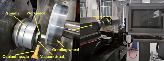
Figure 2. Self-rotating grinding platform used to perform experiments on GaN crystals.
Download figure:
Standard image High-resolution imageEquation (4) [21] was used to calculate the uncut chip thickness dg under the grinding conditions used in this study as 0–17.8 nm:
where dg is the uncut chip thickness, Rg is the abrasive radius, fs is the feed speed, r is the distance from the workpiece center, nw is the rotational speed of the work material, ds is the outer diameter of the wheel, bs is the width of the wheel, γ is the volume content of the abrasives, and ns is the wheel rotational speed.
3. Results and discussions
3.1. Grinding force and coefficient of friction
Grinding force is an important index for evaluating the machining effect during the grinding process, and indirectly reflects the material removal process and interaction between the abrasives and workpiece. Figure 3 shows the grinding forces under different interacted conditions. Both figures 3(a) and (b) indicate that as the grinding length increases, the grinding force increases and then stabilizes. Therefore, the average grinding force at the stable grinding stage can be used to analyze the influence of the interacted distance on the grinding force. Figure 3(a) also shows that the grinding force is smaller for the second abrasive than the first abrasive because of the elimination of coupling actions between the two abrasives. Figure 3(c) shows that for Lb = 6 nm and increasing La , the grinding force increases and then stabilizes. This result is obtained because increasing La weakens the coupling between the two abrasives, increasing the contact area between the workpiece and abrasives. Figure 3(d) shows that for noninterfering abrasives, there is a specific La at which there is no discernible coupling between the abrasives and the grinding force is approximately twice that of a single grit, that is, La has no discernible effect on the grinding force.
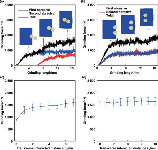
Figure 3. Grinding force for different interacted distances. (a) Grinding force versus the grinding length for radial and transverse interacted distances of 6 nm and 3 nm, respectively. (b) Grinding force versus the grinding length for radial and transverse interacted distances of 0 nm and 8 nm, respectively. (c) Grinding force versus the transverse interacted distance for a radial interacted distance of 6 nm. (d) Grinding force versus the transverse interacted distance for a radial interacted distance of 0 nm.
Download figure:
Standard image High-resolution imageFigure 4 shows the influence of the transverse interacted distance on the coefficient of friction during double-grits grinding of GaN crystals. In this study, the coefficient of friction is defined as the ratio of the tangential force exerted by the abrasive along the grinding direction to the normal force exerted by the abrasive. In figure 4(a), for Lb = 6 nm and increasing La , the coefficient of friction decreases and then increases. The atomic displacements shown in the inset images indicate for La below 3 nm, the contact area between the workpiece and abrasives increases with La . However, there is no discernible increase in the number of atoms that have accumulated in front of the abrasives because of the elimination of coupling between abrasives, which results in the gradual decrease of the coefficient of friction. For La above 3 nm, as La increases, the effect of eliminating the coupling between abrasives weakens and the number of atoms that have accumulated in front of the abrasives increases, resulting in the gradual increase of the coefficient of friction. Figure 4(b) shows that for Lb = 0 nm, La has no discernible effect on the coefficient of friction. Selecting appropriate interacted distances can effectively reduce the friction between the workpiece and abrasives below that of single-grit grinding while ensuring efficient material removal, providing a feasible approach to the wheel design of ordered abrasives.
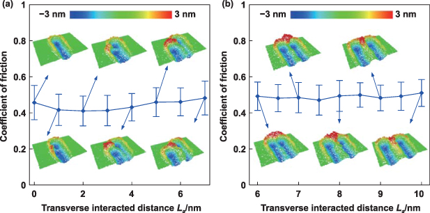
Figure 4. Coefficient of friction under different interacted distances. (a) Coefficient of friction versus the transverse interacted distance for a radial interacted distance of 6 nm. (b) Coefficient of friction versus the transverse interacted distance for a radial interacted distance of 0 nm. The atomic displacements at different interacted distances are shown in the inset images.
Download figure:
Standard image High-resolution image3.2. Stress distribution
The stress investigated in this study corresponds to the von Mises stress, which was calculated by the spatial average method. Figure 5 presents the stress distributions for different transverse interacted distances when the radial interacted distance is 6 nm. The average stress induced by the second abrasive during double-grit grinding (∼49.5–57.5 GPa) is smaller than that induced during single-grit grinding (∼58.1 GPa) because of the elimination of the coupling to the first abrasive. When the transverse interacted distance is 1 nm, the average stress induced by the second abrasive is 14.8% lower than the average stress induced during single-grit grinding. As the transverse interacted distance increases, the coupling removal of the first abrasive weakens, causing the stress induced by the second abrasive to gradually increase and approach that induced during single-grit grinding.
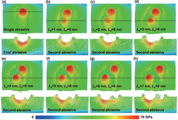
Figure 5. Stress distributions for different transverse interacted distances and a radial interacted distance of 6 nm. (a) Single-grit grinding, and (b)–(h) double-grit grinding with transverse interacted distances of 1 nm, 2 nm, 3 nm, 4 nm, 5 nm, 6 nm, and 7 nm, respectively.
Download figure:
Standard image High-resolution imageFigure 6 presents the stress distributions under different transverse interacted distances when the radial interacted distance is 0 nm. When the transverse interacted distance is 6 nm, large stresses in the workpiece are mainly concentrated between the two abrasives as well as below the abrasives because of the pushing action of these abrasives. As the transverse interacted distance increases, the coupling effect between the abrasives gradually weakens. Therefore, the stress on the subsurface gradually decreases, and the large stress is gradually transferred to the region below the two abrasives. In addition, the number of chips accumulated between the two abrasives gradually increases with the transverse interacted distance. A very low stress is exerted on the chips because the abrasives no longer push on the material after the chips form.
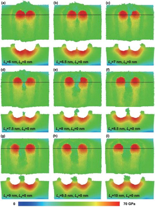
Figure 6. Stress distributions under different transverse interacted distances when the radial interacted distance is 0 nm. The transverse interacted distances of (a)–(i) are 6 nm, 6.5 nm, 7 nm, 7.5 nm, 8 nm, 8.5 nm, 9 nm, 9.5 nm and 10 nm, respectively.
Download figure:
Standard image High-resolution image3.3. Subsurface damage
It is crucial that MD simulations accurately predict material damage phenomena. Therefore, it is particularly important to determine the subsurface damage mechanism of GaN crystals during interactive double-grit grinding. The machining scale in an MD simulation is considerably smaller than the depth of the brittle-to-ductile transition region in GaN crystals. Thus, the simulated subsurface damage is plastic damage, as shown in figure 7. The simulated results demonstrate that the plastic damage of GaN crystals induced by double-grits grinding is dominated by the amorphous transition, high-pressure phase transition, dislocations, stacking faults, and lattice distortions. The atoms in the chips and groove surfaces have high energy and weak structural stability and are therefore most prone to amorphization [64, 65]. The results of Zhang et al [66] and Jiang et al [67] lead to the conclusion that the maximum stress induced by machining does not occur at the ground surface underneath the abrasive but at a certain distance from the ground surface in the plastic zone. Therefore, the high-pressure phase transition zone lies below the amorphous layer. The plastic zone is surrounded by a large number of stacking faults and dislocations because of the effect of subsurface stress at the boundary of the plastic zone [68, 69]. To eliminate the interference of elastic deformation on the identification of lattice distortion, we selected an area far away from the abrasive after elastic recovery to identify the lattice distortion. Therefore, the results presented in figure 7(h) were confirmed to be lattice distortion rather than elastic deformation. Figure 7(i) shows the phase transition path from hexagonal GaN to cubic GaN that occurs during the grinding process. It can be observed that the high pressure caused by the abrasive destroys the atomic arrangement and lattice structure. The high pressure induced by the abrasive destroys the atomic arrangement and lattice structure. The barrier to the phase transition is overcome by the generation of unstable intermediate phases between the hexagonal and cubic structures. As the pressure increases, the content of hexagonal GaN gradually decreases and the content of cubic GaN gradually increases and then stabilizes. An experiment was performed to confirm the simulation results.
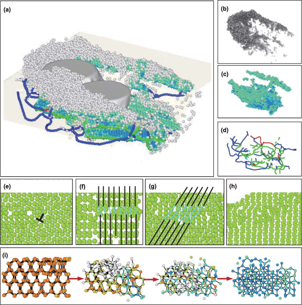
Figure 7. MD simulated results of subsurface damage mechanism of monocrystalline GaN induced by double-grits interacted grinding. (a) Overall damage morphology, (b) amorphous region (gray atoms), (c) cubic diamond atoms (green atoms), (d) and (e) dislocations (blue, orange, green, and purple lines), (f) and (g) stacking faults, (h) lattice distortions, and (i) phase transition path from hexagonal GaN (orange atoms) to cubic GaN (blue atoms). The radial and transverse interacted distances are 6 nm and 3 nm, respectively.
Download figure:
Standard image High-resolution imageAn experiment was performed to characterize the ground subsurface to validate the MD simulation results of the effect of coupling between abrasives on material damage and removal during grinding. Figure 8 shows the bright field (BF) TEM images of damage behaviors of the ground subsurface. The diffraction spots shown in figure 8(d) indicate that the original GaN substrate is a perfect single crystal with a zone axis of [11–20]. Figure 8(a) indicates that the ductile subsurface does not contain cracks and brittle fractures, and a plastic damage layer lies 200 nm beneath the ground surface. Figures 8(b) and (c) show that high-density stacking faults and dislocations are one of the main forms of plastic damage that occurs in GaN crystals during grinding. The main plastic deformation zone lies above the stacking fault and dislocation zones, which is similar to the subsurface damage induced by the quasi-static scratching [33]. To understand the essence of the main plastic deformation zone, more HR-TEM experiments need to be performed to characterize the main plastic deformation zone. The stacking faults generated under a high strain rate differ from those generated by low-strain-rate nanoscratching [33]. Only high-density stacking faults parallel to the (0001)-orientation plane are generated during the low strain-rate nanoscratch test. Figures 8(b) and (c) and (e) show that in addition to the stacking faults parallel to the (0001)-orientation plane, high-density stacking faults parallel to the {-1101} and {1-101} directions are generated during grinding. This phenomenon occurs because compared to low-strain-rate nanoscratching, grinding generates a considerably higher strain rate, which induces a higher stress on the subsurface and activates crystal-plane slip along more crystal directions.
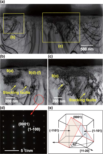
Figure 8. TEM results of subsurface damages. (a) Bright-field transmission electron microscopy (BF-TEM) images of the ground subsurface morphology, (b) and (c) enlarged images of (a), (d) diffraction spots of the monocrystalline GaN substrate, and (e) schematic diagram of stacking faults of the ground subsurface.
Download figure:
Standard image High-resolution imageFigure 9 shows the HR-TEM images of the ground subsurface morphology. Figures 9(a) and (b) prove that surface amorphization is one of the main types of plastic damages in monocrystalline GaN induced by ultra-precision grinding, and figure 9(c) further confirms the existence of the high-density stacking faults. Similar to the simulated results, the surface atoms have relatively high energy and weak structural stability, producing an amorphization layer on the ground surface. The force exerted by the abrasives generates a shear stress along the close-packed plane that destroys the stacking sequence, generating stacking faults. As shown in figure 9(d), the interplanar spacings and included angles demonstrate that cubic GaN is generated by the high-pressure phase transition behavior. Figures 9(e) and (f) prove that dislocations and lattice distortions are also main forms of plastic damages induced in the grinding process. Lattice distortions increase the internal energy of materials and hinder dislocation slip. The TEM micrographs presented in figures 8 and 9 indicate that the forms of plastic damages from the ground surface to the subsurface are amorphous atoms, phase transition atoms, and a combination of dislocations and stacking faults. The aforementioned experimental results agree well with the MD results, which indicates that the simulated results are reliable.

Figure 9. High-resolution transmission electron microscopy (HR-TEM) images of the ground subsurface morphology. (a) Amorphous and lattice distortions, (b) an amorphous halo ring in the Fourier transformation of (a), (c) high-density stacking faults, (d) cubic GaN generated during the high-pressure phase transition, (e) dislocations, and (f) lattice distortions.
Download figure:
Standard image High-resolution imageThe subsurface damage depth is one of the important indicators for evaluating the surface integrity during the ultra-precision machining of brittle materials [70, 71]. In this study, all the amorphous atoms, phase transition atoms, dislocations, stacking faults, and lattice distortions underneath the residual surface are regarded as subsurface damages. Therefore, the subsurface damage depth is defined as the distance from the residual surface to the deepest damage. Figure 10 presents the effect of the transverse interacted distance on the subsurface damage depth. Compared with the interacted distance in only one direction, the interacted distance in both radial and transverse directions achieved the shallower subsurface damage. When the radial interacted distance is 6 nm, the damage depth of the ground subsurface increases as the transverse interacted distance increases. The stress analysis in figure 5 demonstrates that increasing transverse interacted distance leads to an increase in the grinding stress of the second abrasive, resulting in an increase in the subsurface damage depth. However, there is no clear correlation between the transverse interacted distance and subsurface damage depth for the radial interacted distance of 0 nm.
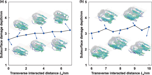
Figure 10. Influence of the transverse interacted distance on the subsurface damage depth. (a) The radial interacted distance is 6 nm, and (b) the radial interacted distance is 0 nm. The inset images are surface and subsurface damages under different interacted distances, including amorphous atoms (gray atoms), cubic diamond phases (gray atoms) and dislocations (blue, orange, green, and purple lines).
Download figure:
Standard image High-resolution imageFigure 11 shows the numbers of amorphous atoms under different interacted distances. As shown in figure 11(a), when the radial interacted distance is 6 nm, the number of amorphous atoms increases as the transverse interacted distance increases. This occurred because increasing transverse interacted distance can improve the material removal volume and grinding stress of the second abrasive, resulting in an increase in the number of amorphous atoms. As shown in figure 11(b), when the radial interacted distance is 0 nm, amorphous atoms increase and then decrease as the transverse interacted distance increases. When the transverse interacted distance is below 8 nm, as the transverse interacted distance increases, material removal volume and chip deformation increase, resulting in an increase in the number of amorphous atoms. However, when the transverse interacted distance is above than 8 nm, the grinding stress decreases as the transverse interacted distance increases, resulting in a decrease in the number of amorphous atoms.

Figure 11. Influence of the transverse interacted distance on the number of amorphous atoms. (a) The radial interacted distance is 6 nm, and (b) the radial interacted distance is 0 nm.
Download figure:
Standard image High-resolution imageFigures 12 and 13 show the numbers of phase transition atoms of cubic GaN and dislocation lengths under different interacted distances, respectively. It can be found that there is no clear correlation between the transverse interacted distance and number of atoms in the phase transition and dislocation length. This occurred because the high-pressure phase transition and dislocation length are determined by the stress and material removal volume. For a constant radial interacted distance and increasing transverse interacted distance, the stress decreases and then gradually stabilizes, whereas the material removal volume increases and then stabilizes. Therefore, transverse interacted distance is not monotonically related to the number of atoms in the phase transition and dislocation length.
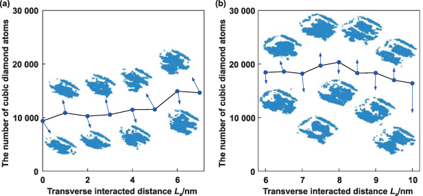
Figure 12. Influence of the transverse interacted distance on the number of cubic diamond atoms. (a) The radial interacted distance is 6 nm, and (b) the radial interacted distance is 0 nm.
Download figure:
Standard image High-resolution image
Figure 13. Influence of the transverse interacted distance on the dislocation length. (a) The radial interacted distance is 6 nm, and (b) the radial interacted distance is 0 nm. The inset images show dislocation loops with different directions. The blue, green, orange, and purple dislocation loops have 1/3<1–210>, <1–100>, 1/3<1–100>, and other crystal orientations, respectively.
Download figure:
Standard image High-resolution image3.4. Abrasive damage
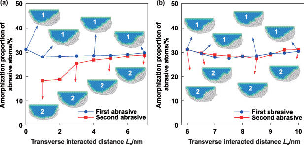
Figure 14 shows that the amorphization transition is the main form of damage behaviors in abrasive wear, such that the proportion of abrasive amorphization can be used as a measure of the damage degree of the abrasives [72, 73]. The morphologies of the abrasives after grinding show more severe amorphization damage at the flank face than that at the rake face. The high elastic recovery rate of the residual GaN material under a high contact stress during grinding [74, 75] makes the flank face prone to friction after grinding than the rake face, resulting in severe wear of the flank face. As shown in figure 14(a), when the radial interacted distance is 6 nm, the amorphization proportion of the first abrasive is larger than that of the second abrasive for the same scratch lengths. As the transverse interacted distance increases, the amorphization proportion gradually increases and then stabilizes. This result is obtained because the elimination of coupling to the first abrasive reduces the volume of material removed by the second abrasive and the elastic recovery depth of the residual materials, effectively reducing the contact stress and flank wear induced by the elastic recovery of the residual materials. The stress generated by the second abrasive also suppresses the elastic recovery of the residual materials of the first abrasive, reducing the flank wear of the first abrasive compared to that of single-grit grinding. As shown in figure 14(b), when the radial interacted distance is 0 nm, there is no clear correlation between the transverse interacted distance and amorphization proportion of abrasive atoms, and the amorphization proportion of the first abrasive is close to that of the second abrasive.
Figure 14. Amorphization proportion of abrasive atoms under different interacted distances (scratch lengths of all abrasives are 10 nm). (a) The radial interacted distance is 6 nm, and (b) the radial interacted distance is 0 nm. Inset images show the abrasive morphologies after grinding, where the blue and gray atoms represent cubic and amorphous diamond atoms, respectively.
Download figure:
Standard image High-resolution image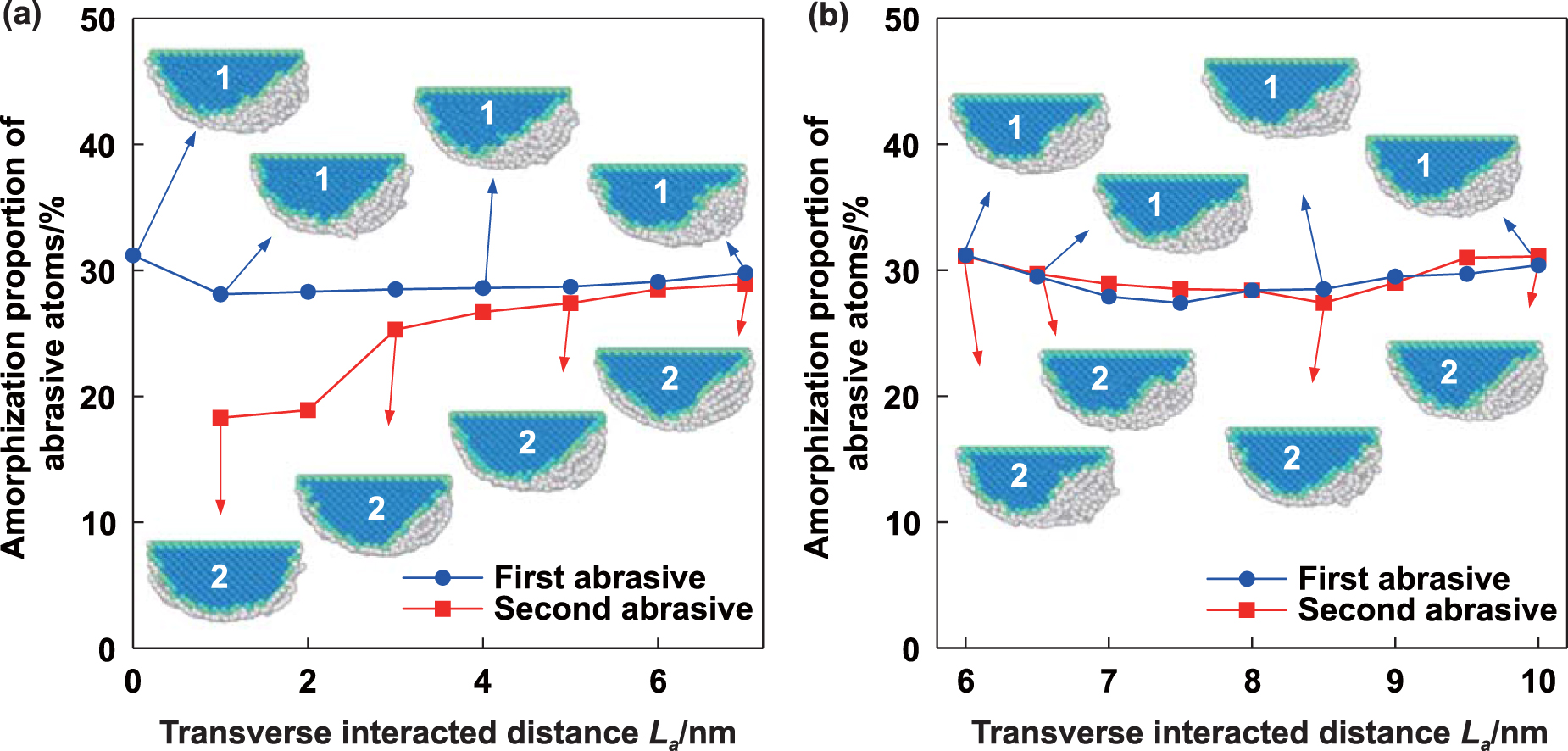
4. Conclusions
The effect of coupling between abrasives on damage accumulation and material removal during grinding of GaN crystals was investigated by conducting MD simulations of interactive double-grit grinding of monocrystalline GaN. The simulated grinding force, coefficient of friction, stress distribution, plastic damage behavior, and abrasive damage were analyzed. The following conclusions were drawn from the study.
- The results of grinding tests combined with cross-sectional TEM micrographs validate the simulated plastic damage behaviors, i.e. the amorphization transition, the high-pressure phase transition, stacking faults, dislocation slips, and lattice distortions. For nonzero interaction distances in both the radial and transverse directions, the damage depth of the ground subsurface increases as the transverse interacted distance increases. There is no clear correlation between the transverse interacted distance and number of atoms in the phase transition and the dislocation length.
- For nonzero distances in both the radial and transverse directions, eliminating the coupling action between the two abrasives results in the second abrasive exerting a smaller grinding force and stress than the first abrasive; as the transverse interacted distance increases, the grinding force and stress increase and then stabilize. Only the transverse interacted distance is nonzero, the stress on the subsurface gradually decreases as the transverse interacted distance increases.
- For nonzero interaction distances in both the radial and transverse directions, elimination of the coupling action between abrasives and the number of atoms that have accumulated in front of the abrasives causes the coefficient of friction to decrease and then increase as the transverse interacted distance increases.
- The amorphization transition is the main form of damage incurred during abrasive wear. Amorphization damage is more severe at the flank face than that at the rake face because of the high elastic recovery of the residual material under a high contact stress. For nonzero interaction distances in both the radial and transverse directions, the amorphization proportion of the first abrasive is smaller than that of the second abrasive for the same scratch lengths. As the transverse interacted distance increases, the amorphization proportion of the second abrasive gradually increases and stabilizes because of the elimination of coupling to the first abrasive.
- Only the transverse interacted distance is nonzero, there is no clear correlation between the transverse interacted distance and the grinding force, coefficient of friction, subsurface damage depth, number of atoms in the phase transition, dislocation length, and abrasive damage.
Acknowledgments
This work was supported by the National Natural Science Foundation of China (52375420, 52005134 and 51675453), Natural Science Foundation of Heilongjiang Province of China (YQ2023E014), Self-Planned Task (No. SKLRS202214B) of State Key Laboratory of Robotics and System (HIT), China Postdoctoral Science Foundation (2022T150163), Young Elite Scientists Sponsorship Program by CAST (No. YESS20220463), State Key Laboratory of Robotics and System (HIT) (SKLRS-2022-ZM-14), Open Fund of Key Laboratory of Microsystems and Microstructures Manufacturing (HIT) (2022KM004), and Fundamental Research Funds for the Central Universities (Grant Nos. HIT.OCEF.2022024 and FRFCU5710051122).
Author statement
This work 'Damage evolution and removal behaviors of GaN crystals involved in double-grits grinding' was original research that has not been published, and not under consideration for publication elsewhere, in whole or in part.