


Abstract
Carbon nanomaterials including, but not limited to, carbon nanotubes (CNTs) and graphene have attracted considerable attention due to their nanoscale electrical conductivity. Flexible sensors have experienced a growing demand due to several potential applications, such as personalized health monitoring and robots. In this study, CNT/cellulose composite sheets were manufactured using spray methods for flexible sensors. MWCNTs were ultrasonically dispersed in an acetone solvent and flexible plain paper was used as a substrate on which the CNT suspension was sprayed. At the end of the coating process, to remove the acetone solvent, the specimens were dried in an oven. Electrical resistance (ER) three-dimensional-mapping and optical observation were used to confirm and evaluate the dispersion of CNTs on the paper. To access the wettability of CNT/cellulose sheets, the changes of static contact angle of distilled water droplets on the sheets were measured. The critical point of the CNT coating numbers was determined using the ER method as well as the change of wettability using the static contact angle measurements.
Export citation and abstract BibTeX RIS

Original content from this work may be used under the terms of the Creative Commons Attribution 4.0 license. Any further distribution of this work must maintain attribution to the author(s) and the title of the work, journal citation and DOI.
1. Introduction
Carbon nanomaterials including, but not limited to, carbon nanotubes (CNTs) and graphene [1] have attracted considerable attention for a variety of uses, in both research and industry, due to their unique mechanical and electrical properties [2]. The high electrical conductivity, high aspect ratio and cylindrical shape of the CNTs, have made them interesting components for the preparation of conductive polymer nanocomposites [3]. To use their electrical conductive properties, CNT nanoparticles are coated on electrical insulating materials such as bio materials [4], ceramics [5] and polymers [6].
Flexible sensors have experienced a growing demand in several potential applications, such as personalized health monitoring, human motion detection, structural health monitoring, smart garments, and robots [7, 8]. Mechanical deformation can often be sensed by electrical signals [9, 10]. However, many flexible materials such as polymers are not electrical conductive. This gives rise to a desire to combine electrical conductive nanoparticles with such flexible materials [11–13].
While properties such as electrical conductivity and flexibility are desirable in many applications, good interfacial adhesion between the substrate and the nanoparticle material is crucial [14, 15]. The challenge is to simultaneously achieve good interfacial adhesion to flexible sensors while maintaining its flexibility [16]. To improve the adhesion of as-deposited materials to a substrate, two common interfacial bonding architectures have been designed, i.e. anchor absorption and covalent grafting. Anchor absorption refers to changing the surface roughness yielding a robust interphase to grasp the coatings. This is accomplished by several means including surface etching, plasma treatments and chitosan attachment. Covalent grafting proceeds via a 'grafting to' mechanism with specific monomers, such as surface silanization, photocatalytic oxidation and polymer grafting [17].
Contact angle measurements are widely used for investigating surface characteristics of materials [18]. The determination of the wettability of solid surfaces is an important problem in surface science for a variety of practical applications [19]. The Young–Dupre equation is used to describe the wettability in terms of the contact angle of a liquid drop on a surface [20]. An electro-micromechanical technique has been proposed and studied as an economically feasible nondestructive evaluation (NDE) method to monitor strain sensing. In this technique, conductive materials act as sensors as well as reinforcing materials and it has become an especially-useful research tool.
In this study, the CNT/cellulose composites sensor was manufactured using spray methods for manufacturing the strain sensor. CNTs were ultrasonically dispersed in an acetone solvent. The CNT suspension was sprayed on cellulose paper used as a substrate. At the end of the coating process, the specimens were dried in an oven to remove the solvent. After manufacture of CNT/cellulose composites sheets, the area of the CNT particles for different conditions of manufacture was observed by captured photos as well as the wettability of CNT/cellulose sheets determined by static contact angle measurements. To determine the dispersion of CNT particles in detail, a electrical resistance (ER) three-dimensional (3D)-mapping method was introduced. The optimal conditions of CNT/cellulose sensors were ascertained via static contact angle and electrical resistance methods. To make a zigzag pattern on the paper, an OHP film cut in a zigzag pattern in advance was piled on the paper. Dispersion of the CNTs and the effects of strain deflection were measured using an ER method and its 3D-mapping.
2. Experimental
2.1. Materials and specimens
Plain paper (A4, Double A, Thailand) was used for the substrate. MWCNT (MR-99, Carbon Nano-Material Technology Co., Korea) was used as the conducting medium. Acetone (Daejung Chemical Inc. Kore) used as the coating dispersive solvent. Figure 1(a) shows an outline of how the CNT/paper sensors were manufactured. CNT was ultrasonically dispersed in an acetone solvent for 1 h. The concentration of the CNT dispersed suspension was 10 wt%. The paper used as the substrate was sprayed with CNT suspension in a zigzag pattern on the paper using the OHP film cut in a zigzag pattern as previously described. After the coating process, the specimens were dried in an oven at 60 °C to remove the solvent.

Figure 1. Schematic plots of: (a) manufacture of CNT/paper sensors; and (b) measurement of static contact angle, ER mapping and strain sensing.
Download figure:
Standard image High-resolution image2.2. Methodologies
2.2.1. Morphology of CNT coatings at the number of spray coating.
After different number of spray coating on cellulose paper, each photo was captured by digital microscope (AM4815TL, Dino-Lite, Taiwan). To calculate the CNT ratio in contrast to paper visually, different pixels between light and shade from the photos were interpreted by the Korea Standard Color Analysis (KSCA) program.
2.2.2. ER measurement.
The ER of the CNT/cellulose composites sheets was measured using a surface resistance measurement machine (FRR-RS8, DASOL ENG, Korea) with four-probe method [21] based on ASTM F1529-97 [22]. The key advantage of the four-probe method is that the separation of current and voltage electrodes eliminates the impedance contribution of the wiring and contact resistances, yielding a measurement of only the resistance between the two inner probes. In this method, the surface resistance was calculated by means of a dual configuration method, which makes use of a comparison of the measurements from the configuration shown in the left sketch, Ra with that of the configuration in the right sketch, Rb of figure 1(b). This method has been shown to greatly reduce edge effects and to yield more uniform values of the ER [23]. The equations for this dual configuration method are shown in the following:


The dispersion of CNT particles was observed using ER mapping methods. Figure 2 shows a schematic sketch of the arrangement of 1 cell used for 2D ER mapping [24]. A total of 16 surface ERs were measured with four times in width and four times in length at the square specimen.

Figure 2. Arrangement of 2D ER mapping on a 1 cell ER.
Download figure:
Standard image High-resolution imageTo compare with dispersion of CNT particles at different number of spray coating equally, the change in electrical resistance, ΩM was suggested as:

where Ω is one of the surface ER and Ωave was the average of surface ER at each condition of the number of spray coatings.
2.2.3. Wettability measurement.
Wettability was determined from the measured static contact angles for double purified water. The static contact angle of these droplets and the substrates was measured directly from photographs taken by an optical microscope. Furthermore, the change of static contact angle as a function of time was measured to determine the optimal number of spray coatings. In general, the static contact angle was calculated using the Young equation:

where γL, γSL and γS are the liquid surface tension, the solid/liquid interfacial energy and the solid surface energy, respectively [25, 26].
3. Results and discussion
3.1. Morphology of CNT coatings at the number of spray coating
Figure 3 shows the photos of CNT coatings on paper versus the number of spray coatings. The white regions are the white cellulose and the dark regions of the CNT coating. Using the different pixel between light and shade from such photos, the CNT ratio was calculated and is shown in the plot in figure 3. The CNT ratio increased dramatically until at 10 coating numbers almost 100%. After that, the CNT ratio increased slightly to CNT coatings. The CNT particles could be adhered with surface of cellulose paper until 10 coating numbers. After then, however, the CNT particles were stacked together on CNT layer by themselves since the CNT particles for adhesion with cellulose paper had been already saturated.
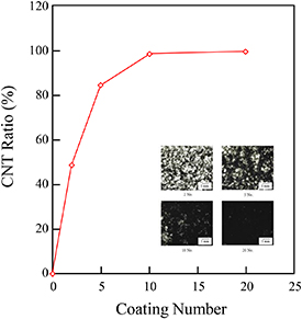
Figure 3. Area of CNT on paper for different numbers of coating.
Download figure:
Standard image High-resolution image3.2. Surface properties with number of spray coating
Figure 4(a) shows the change of static contact angles with elapsing time on CNT/cellulose composites sheet with different coating numbers. Initial static contact angles of each condition were similar whereas change of static contact angle with elapsing time decreased differently. Figure 4(b) shows the change in static contact angle ratio with different coating numbers. Each change in static contact angle ratio was expressed as the ratio of measured contact angle compared to the initial contact angle. Figure 4(b) exhibits a transition at 10 coating numbers for various elapsing times. At 2 coating numbers the change in static contact angle ratio was shown steeply. The change in static contact angle ratio was shown moderately until 10 coating numbers whereas the change in static contact angle ratio was shown rather steeply again after 10 coating numbers. The repelling against water with 10 coating numbers was highest among different coating numbers.

Figure 4. Change in static contact angle on CNT/paper sheet in dependence on: (a) time and (b) coating number.
Download figure:
Standard image High-resolution image3.3. ER of CNT/paper sheets
Figure 5 shows the ER of surfaces of CNT/paper sheets versus the number of CNT coatings. The ER decreased rapidly until 10 coating numbers after which it remained relatively constant to 20 coatings. To illustrate the dispersion of CNT particles on paper, ER 3D-mapping from 2D ER results are shown in figure 6. Through the ER 3D-mapping, the dispersion of CNT particles became relatively uniform at 10 coatings as shown by little color changes in ΩM. However, there was more color displayed after 20 spray coatings. The authors attribute this to the excessive spray coatings of CNT particles prohibiting the dispersed surface of CNT particles.

Figure 5. ER of CNT/paper sheets versus number of coatings.
Download figure:
Standard image High-resolution image
Figure 6. ER 3D-mapping of CNT/paper sheets coating.
Download figure:
Standard image High-resolution imageFigure 7(a) shows the photos of the change in ER of a CNT/paper composite sensor during fatigue bend testing. Figure 7(b) shows a graph of ER during bending of a sensor for several cycles for such a test. While the ER of the sensor responded to the bending in each cycle, a shift in the ER with additional cycles was also observed.

Figure 7. Bending test of CNT/paper sensor: (a) photos of tests and (b) ER during at bending.
Download figure:
Standard image High-resolution imageFigure 8(a) shows schematic plots of static contact angles and change of ER during bending for CNT/cellulose composite sheets. For fewer coatings of CNT, the area of hydrophilic cellulose was higher than for CNT leading to a relatively low static contact angle. For excessive coatings of CNT, the stacking of CNT particles led to a reverse effect of relatively hydrophilic surface. For the effects on ER, the ER decreased up to 10 coating numbers which is attributed to an increase in pathway via percolation of the CNT particles. For more than 10 coating numbers, the ER was maintained because the CNT particles on the cellulose sheets had been saturated and stacked. Figure 8(b) shows schematically the mechanism of strain sensing at bending. Upon bending of the sensor, the gap between CNT particles increases, and the electrical contact among the CNT particles decreases resulting in an increase in the ER.

Figure 8. Schematic plots of: (a) CNT/cellulose sheets for different number of coatings; and (b) bending of electrical conductive sheets.
Download figure:
Standard image High-resolution image
4. Conclusions
CNT/cellulose strain sensors were manufactured using a spray method. CNT was ultrasonically dispersed in an acetone solvent. Paper made of cellulose, used as substrate, was sprayed with this CNT suspension. Through the relative ratio between light (cellulose) and shade (CNT) from captured photo, it was observed that the CNT ratio increased until 10 coating numbers and then the ratio of CNT increased rather slowly. The change in static contact angle ratio decreased until 10 coating numbers whereas the change in static contact angle ratio decreased after 10 coating numbers. For a few CNT coatings, the area of hydrophilic cellulose was higher than that of CNT leading to relative low static contact angles and high ER. With an increase in CNT coating, hydrophobic CNT particles increased and a pathway via percolated CNT particles. However, excessive CNT particles resulted in the change in static contact angle ratio with maintaining the ER due to excess CNT particles. This phenomenon was illustrated by ER 3D-mapping, which was dependent on the number of coatings, proving the degree of dispersion of CNT particles comparatively. After finding the optimal number of spray coatings, CNT/cellulose strain sensors were manufactured and strain sensing tests were demonstrated properly.
Acknowledgments
This work was supported by the National Research Foundation of Korea (NRF) grant funded by the Korea government (MOE) (No. 2016R1D1A1B01012620).