
Abstract
Surgery to implant a total hip replacement (THR) is very successful in reducing pain and restoring function. This procedure has become more prevalent, and projections estimate further increases in demand. However, complications can arise, and current diagnostic techniques often fail to expose underlying issues before they result in a catastrophic failure that requires revision surgery. An instrumented implant, with embedded sensors capable of real time condition monitoring, would be an attractive proposition to incorporate within a THR. Continued advances in the performance and miniaturisation of electronic components, embedded systems, sensing and wireless communications have given the tools and resources medical device manufacturers need to innovate in the field of implantable medical devices. Smart implants are already being widely used in healthcare including pacemakers, cochlear implants, glucose monitors and insulin pumps however, a widely used smart THR has not yet been realised. Since the implantation of the first instrumented hip implant in the 1960s there have been several in vitro studies monitoring levels of implant loosening. Additionally, significant research has been conducted using instrumented THRs to perform in vivo measurement of biomechanical metrics, including force and moments. To date less than 100 patients have successfully received an instrumented implant. The results of these studies have aided researchers, designers and surgeons in wider research projects, however, the motivation behind the work was to provide discrete biomechanical data sets and not provide real-time condition monitoring of an implants performance or highlight early indications for revision surgery. If in vivo sensing within a THR is to be achieved and adopted in regular clinical practice then the following challenges need to be addressed: choice of the sensing method, biocompatibility and integration within the implant, power supply, communication, and regulatory considerations.
Export citation and abstract BibTeX RIS

Original content from this work may be used under the terms of the Creative Commons Attribution 4.0 license. Any further distribution of this work must maintain attribution to the author(s) and the title of the work, journal citation and DOI.
1. Introduction
Total hip replacement (THR) surgery is a successful intervention and relives pain and restores function [1]. National joint registries [2–4] have all shown consistent increase in the number of THR surgeries performed annually and projections are estimate further growth in the demand for both primary and revision procedures [5, 6]. Furthermore, patient expectations are changing as younger patients are undergoing THR and increasingly demand return to recreational activities [7]. Despite the success of THR surgery, complications can still arise, and current diagnostic techniques often take too long to expose underlying issues before they result in catastrophic failure which may result in revision surgery. Revisions are undesirable because of increased surgery time, complication rates and expense. Equally, unnecessary clinical reviews of well-functioning THRs are routinely carried out because there is no alternative to assess on-going function. The use of in vivo sensing capable of real time condition monitoring of the implant's performance, occurrence of adverse events and patient health metrics offers a potential solution. Research in this area was first explored in the 1960's, however, despite almost 60 years of continued innovation, there has not been widespread adoption in orthopaedics. Recent advancements in materials, manufacturing and electronics may provide new potential innovations in the field of in vivo sensing and smart implants thus making it an opportune moment to conduct a review on past systems and applicable technology.
1.1. Why is it desirable to have telemetry in an implanted medical device (IMD)?
An IMD with sensing capabilities and telemetric link could provide a means of continuous monitoring as oppose to traditional episodic monitoring [8]. This would enable clinicians to track the post-operative recovery process, better guide personalised postoperative care [9, 10] and empowers patients with the ability to review and manage the health of their implant. Additionally, the system could provide alerts on the occurrence of adverse events to give an early indication of the need for further investigation, or modification in activities.
Increased availability of cheaper, smaller and more powerful integrated circuits and semiconductors has led to huge technological advances in electronics, sensing and communications. These advances and increased adoption of technology in healthcare has meant that smart IMDs are becoming a reality and are commonly used across healthcare. For example, the Freestyle Libre continuous glucose monitor (Abbott, Ill, US) offers an alternative to traditional finger prick blood glucose tests. The Freestyle Libre offers a pain free method for continuously measuring blood glucose levels and information on the direction blood glucose levels are trending. This demonstrates an example of how the advent of technology has improved both the convenience and quality of the care.
The data gathered by an instrumented implant could inform the healthcare professional during their diagnostic decisions. In the case of a THR this data could include (for example) metrics on the performance of the implant or activity of an individual patient such as daily steps, range of motion, and condition of the bone-implant bond or wear of the bearing surfaces. Furthermore, this data would also be valuable to researchers to gain a better understanding of the overall use and performance of THRs across a patient population. Ultimately this research could be used to refine the design and surgical placement of existing implants to give enhanced performance and increased longevity. If these improvements were achieved, they would be of benefit patients and clinicians; and also providers (healthcare systems) and financiers (governments and insurance companies).
1.2. How do hip implants fail?
The common indications and percentage occurrence for primary revision following primary THR surgery (that occurred in England, Wales, Northern Island, the Isle of Man and the States of Guernsey from 1 April 2003 to 1 March 2020 [2]) are summarised in figure 1. In the short term (less than 1 year after primary hip replacement), the most common indications for revision (as measured by failures per 1000 prosthesis-years) were dislocation/subluxation (2.50), infection (1.92), peri-prosthetic fracture (1.71), aseptic loosening (1.03), reaction to particulate debris (0.77) and malalignment (0.73). Clearly pain cannot be detected by means of an instrumented implant however there is scope for the other listed indications to be detected in vivo.
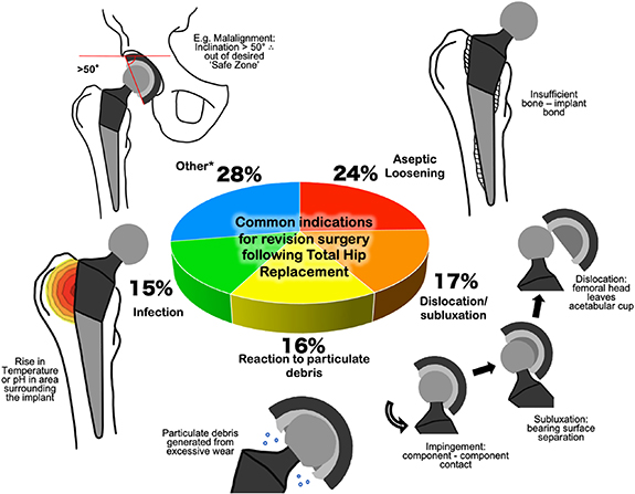
Figure 1. Common indications for primary revision following primary revision surgery as reported by the 17th Annual Report of the National Joint Registry [2]. *Other indications of note include malalignment, implant wear and implant fracture.
Download figure:
Standard image High-resolution imageThe indications for revision demonstrate different modes in which an implant can fail, all may be linked to patient reported pain. This can make an initial diagnosis through clinical observations a challenge. An instrumented hip implant could give quantitative data demonstrating an adverse event providing an early indication for the need for clinical review. This could reduce the diagnostic pathway providing a quicker diagnosis thus reducing the impact of time sensitive conditions [8].
This review will look at the current state of the art of instrumented hip implants focusing on their capability to perform in vivo sensing and translation into routine clinical practice. Following this the challenges that will need to be overcome for in vivo sensing systems to be viable will be considered. These are as follows: choice of sensor (including author recommendations on potential sensing applications for use within a THR), biocompatibility and integration within the implant, power, communication, and regulatory considerations.
2. Review: instrumented hip implants current state of the art
The review's findings are reported in sections on related to the indication for revision or main phenomena that the study was looking to detect or monitor; (i.e. biomechanics and aseptic loosening).
2.1. Biomechanics
In terms of instrumented hip implants, most of the focus has been on studying the biomechanics of THRs and function in an in vivo environment. Strain gauges, piezoelectric transducers and temperature sensors have been used to measure forces, pressures, moments and temperatures in vivo. The data collected in these studies has been important in validating computational and cadaveric models, and inform designers and surgeons thus improving implant design and surgical technique.
2.1.1. Early work on measuring hip joint force in vivo
The first use of sensors in an instrumented implant, for in vivo use, was that of Rydell et al [11] who positioned strain gauges within the neck of the femoral prosthesis. The prosthesis was implanted successfully in two patients successfully and 6 months later a 2nd surgery passed lead wires out of the skin to allow for data collection. After a week these lead wires were designed to be cut free by a sharp edge at the junction with the prosthesis however this method failed, and a separate operation had of be conducted to remove the leads. Results (in terms of measured load) were recorded from two patients were collected (table 1).
Table 1. Summary of studies reporting in vivo loads measured through hip joint.
| Study | Method | Patients | Stance/activity | Measured load through joint normalised to body weight |
|---|---|---|---|---|
| Rydell et al [11] | Six strain gauges in stem | 2 | One-legged stance | 2.3× (peak patient 1) and 2.9× (peak patient 2) |
| Walking 1.3 m s−1 (patient 1) and 1.4 m s−1 (patient 2) | 1.8× (peak patient 1) and 3.3× (peak patient 2) | |||
| Kilvington and Goodman [13] | Load cell piston | 1 | One-legged stance | 2.8× (12 d post-op) and 2.2× (40 d post-op) |
| Walking | 2.0× (12 d post-op) and 1.9× (40 d post-op) | |||
| Davy et al [25] | Three strain gauges matrix method | 1 | One-legged stance (31 d post-op) | 2.1× |
| Walking | 2.6× to 2.8× (range) | |||
| Stair climbing | 2.6× | |||
| Kotzar et al [26] | Three strain gauges matrix method | 2 | One-legged stance (23 d post-op) | 2.1× to 2.8× (range) |
| Walking | 2.8× to 3.6× (range) | |||
| Bergmann et al [27] | Three strain gauges matrix method | 2 | Walking 0.3 m s−1 (patient 1) and 1.4 m s−1 (patient 2) | 2.8× (peak patient 1) and 4.8× (peak patient 2) |
| Stumbling | 7.2× (peak patient 1) and 8.7× (peak patient 2) | |||
| Bergmann et al [21] | Three strain gauges matrix method | 4 | One-legged stance | 2.3× (mean from four patients) |
| Walking (1.1 m s−1) | 2.4× (mean from four patients) | |||
| Damm et al [24] | Three strain gauges matrix method | 8 | Walking (3 months post-op) | 2.5× (mean from eight patients) |
Convenience, improved patient comfort and reduced risk of infection led to the use of wireless connections. An approach, first described by English and Kilvington [12] and later in Kilvington and Goodman [13], was to use battery power and a FM transmitter chip (Sandev SNlO2F) operating at 102.3 MHz. Their implant consisted of a sealed piston with four strain gauges thus forming a load cell capable of measuring the axial compressive load transmitted through the neck of the femoral component. A cable was passed out of the implant stem and led to an implanted Perspex box where the transmitter and accompanying electronics were housed, the cable and box were encapsulated within silicone rubber. The system had an operational battery life of approx 70 h and with the use of sub miniature magnet controlled reed switches, recordings could be made up to 43 d post-op [12]. Results (load from walking and one legged stance) from a single patient were collected (table 1).
Other early work measured contact pressures at the joint surface, Carlson et al [14] developed a prototype prosthesis to measure the magnitude and distribution of pressure generated over the inner surface of a natural human hip socket. The implant featured 14 pressure transducers covering the outer surface of the femoral head, and a 16-channel telemetry system located within the femoral head. The power and data transfer induction coil were located at the distal end of the implant, allowing the implant to be powered by an external power coil. A similar approach was adopted by Otake et al [15] who developed a modified femoral head with eight sub-miniature pressure sensors embedded over the surface and covered with a spherical ABS plastic surface to reduce friction. The device was limited in that it was only intended to measure intraoperative pressures at the bearing contact surfaces.
2.1.2. 3D force measurements acting on the femoral stem
In 1979 Georg Bergmann developed a new method for measuring force distributed over a femoral head termed the matrix method [16]. The method required only one sensor for each load component and so meant that 3D force measurements could be made on the femoral head with the use of only three strain gauges positioned within the femoral neck (on the inner surface). Bergmann then developed his own instrumented hip implant that he initially tested in sheep [17]. A functional telemeterised hip for in vivo human use was first described and implanted in 1988 [18]. The implant, (figure 2(a)), included three semiconductor strain gauges positioned on the inner wall of the hollow neck. The remaining electronics, including the power coil and RF transmitter, were placed on both sides of a 15 mm × 7 mm wide substrate and housed in an 8 mm × 25 mm cylinder. The top plate of the cylinder had two lead throughs that connect to the RF transmitter antenna which was fitted into the cavity of a ceramic head [19]. Two patients received the instrumented hips, firstly in 1988 a bilateral procedure (both hips) was performed on an 82 year old male with height 168 cm and bodyweight (BW) 650 N, and then in 1990 in the right hip of a 69 year old female of height 160 cm and BW 470 N. Results recorded (peak loads in walking and stumbling) from the two patients are shown in table 1.
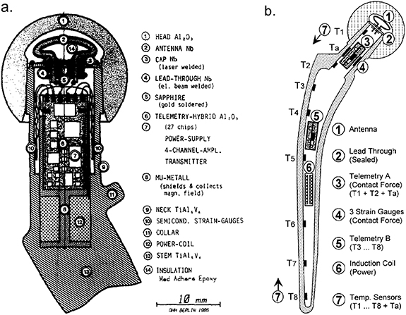
Figure 2. (a) Cross section of Bergmann's first hip endoprosthesis for force measurements. Reprinted from [18], Copyright (1988), with permission from Elsevier. (b) Bergmann's hollow shaft smart prosthesis capable of force measurement and temperature measurement along the full length of the stem. Reprinted from [22], Copyright (2001), with permission from Elsevier.
Download figure:
Standard image High-resolution imageIn the 1990s Bergmann et al developed a further endoprosthesis which measured the force components experienced by the head and also the temperature distribution across the full length of the femoral stem [20]. The implant, (figure 2(b)) was based on the hollow shaft hip endoprosthesis CENOS (ARTOS, Berlin, Germany) and featured three semiconductor strain gauges and two temperature sensors (TS1 and TS2; figure 2(b)) glued to the inner surface of the hollow neck along with an additional six temperature sensors (TS3–TS8; figure 2(b)) positioned along the shaft of the stem. The power coil and two telemetry units were positioned within the hollow shaft, which was sealed by a top plate. The top plate was welded to the top of the implant neck, and featured two lead throughs that allowed connection to the antenna that occupied the cavity of the ceramic head [20], similar to the previous endoprosthesis [19].
In 2001 Bergmann et al published the results of two studies conducted using these new endoprosthesis [21, 22]. Firstly, contact forces were reported from four patients', age range 51–76 years and BW range of 702 N–980 N. Hip contact force results collected from these four patients are shown in table 1. In the 2nd study temperature measurements were made in seven patients', age range 51–82 years. Peak temperature of implants with a polyethylene liner was measured at 43.18 °C after an hour of walking and was observed in sensor TS1 which was positioned at the top of the neck [22], (figure 2(b)).
The 3rd iteration of Bergmann's instrumented hip prosthesis [23] was based on a 'cementless tapered wedge' (CTW) prosthesis (Merete Medical GmbH, Berlin, Germany). This allowed for the measurement of forces and moments acting in the joint. Three custom-made twin semiconductor strain gauges were positioned inside the hollow neck along with a nine-channel telemetry transmitter and an internal induction coil. A cut-out model of the prosthesis is shown in figure 3(a). The prosthesis had a transmission range of 50 cm [23]. In 2013 Damm et al [24] reported in vivo friction measurements using Bergmann's modified CTW prosthesis. Results at 3 months post-op from eight subjects, age range 50–69 years and BW range of 754 N–899 N and are shown in table 1. Since then other studies have used the prosthesis to measure loads through the hip joint for a variety of movements including aquatic exercises [33], cycling [34] gymnastics and aerobic exercises [35].
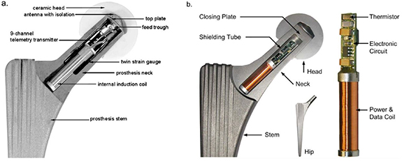
Figure 3. (a) Bergmann's first CTW implant with three twin semiconductor strain gauges, internal power coils and an external niobium antenna. Reprinted from [23], Copyright (2010), with permission from Elsevier. (b) The latest of Bergmann's smart implants and the first to feature a combined power and data transfer coil. Reproduced from [28]. CC BY 4.0.
Download figure:
Standard image High-resolution imageBergmann et al [28] also developed a further prosthesis based on the CTW design solely for in vivo temperature measurements. This had a 6.2 mm diameter × 50 mm long bore in the neck for the thermistor and accompanying electronics, (figure 3(b)). Bergmann's previous implants had all featured internal power coils and an external niobium antenna. The new prosthesis however, had a combined power and data coil positioned within a hermetically sealed chamber instead of being positioned in the recess of the femoral head and encapsulated in silicone. The justification being that the plastic encapsulation of electronics should only be used for non-permanent implants [28]. To date no study has been reported from this prosthesis however, Bergmann et al [28] and Damn et al [36] state that a clinical study on temperature rise in hip implants was planned in 100 patients.
2.2. Implant loosening
Aseptic loosening is failure of the implant—bone bond in the absence of infection. It is the most common reason for orthopaedic implant revision. Aseptic loosening can cause pain and if it is diagnosed too late, can lead to a destruction of bone stock which can create issues when implanting a new revision implant [29]. The initiation and progression of aseptic loosening is multifactorial, this includes: resultant adverse biological reactions to cement, polyethylene, metal or ceramic particles, micromotion at the interface, stress shielding, high fluid pressure, endotoxin or individual and genetic variations [30].
2.2.1. Vibration analysis (VA)
VA relies on measuring the ambient vibrations and frequencies of a system or the vibration response following a mechanical excitation from an external source e.g. a shaker. A structural change or degradation within the system, for example an imbalance, worn and broken components or torque variations, will give rise to distinct features in the output signals. An abnormal vibration response can be more easily identified if an original or typical vibration response is known [31]. The frequency response of a linear system will show the excitation (input) oscillating at the same frequency as the output. Whereas the output of a nonlinear system will contain multiple harmonics. In the case of a THR, a well-fixed prosthesis can be considered as a linear system whereas an unstable or loose implant will behave like a nonlinear system, figure 4.

Figure 4. Conceptual diagram of VA being performed on a femur and implanted stem. The output waveform of a well-fixed implant will match the sinusoidal nature of the input excitation and frequency analysis will reveal one major frequency. Conversely a loose implant will have a distorted output waveform and multiple harmonics will be present. Reprinted from [32], Copyright (1989), with permission from Sage Journals.
Download figure:
Standard image High-resolution imageChung et al [37] first suggested the use of VA as a diagnostic technique to assess THR fixation. They described the technique as safe and non-invasive because only a small mechanical excitation was required; that the method could be used on pre-existing implant designs and previously implanted prostheses and allow for the real time monitoring of levels of osseointegration. The in vitro experimental setup included a mechanical shaker applying an excitation to the implant–bone system and accelerometer(s) attached to the bone, measuring the vibration response. Several studies report similar findings to Chung et al [37] using a femoral stem implanted in a femur [32, 38, 39], acetabular cup implanted in a Sawbone block [40] and complete THR system implanted in a Sawbone femur and pelvis [41]. Results demonstrate that an implant–bone interface with a loosened implant, gave a distorted output waveform, increased numbers of resonance peaks and a reduction in the magnitude of the fundamental frequency.
Rosenstein et al [32] and Georgiou and Cunningham [42] further developed this concept by conducting in vivo trials using VA to detect THR loosening in vivo. In both studies, a single accelerometer was positioned over the greater trochanter and a vibrator applied excitation to the lateral epicondyle of the femur. Rosenstein et al found that in five patients where the VA test was positive for loosening, it was also observed in revision surgery. Additionally, Georgiou and Cunningham reported their VA method had a sensitivity of 80% and a specificity of 89%, and when compared to the standard radiographic method was 20% more sensitive and able to diagnose 13% more patients. There were however, limitations in the in vivo method; firstly, the technique is unsuitable for patients who could not lie on their side or who experience pain and discomfort induced by the vibrator, in Georgiou and Cunningham's study this accounted for 10% of the patients. Secondly, although the authors took care to position the sensor and shaker with 'good bony contact' variations in patient soft tissue can greatly affect the propagation of the vibrations to the body's surface and so affect the diagnostic capabilities [43].
Using an implant with telemetry presents an alternative method that would allow for ongoing VA assessment of the THR component loosening. Puers et al [44] propose a concept that included a capacitive accelerometer sealed in a titanium can and placed into a recess made in the femoral head (figure 5). The inductive power and data coils were fed through the lid of the titanium can and coil around the superior portion of the neck stem. Puers et al [44] state that having the sensing system within the implant will provide far better results when compared to previous VA methods. One limitation of this integration method is that the required recess incurs significant modification to the femoral head which would affect the bearing function at the articulating interface. Additionally, the coils are within the operating space of the ball and socket joint and are thus vulnerable to damage if primary impingement (contact between the cup and stem) occurred.
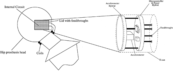
Figure 5. Method of packaging showing the location of the recess in the femoral head and positioning of the transmission coils. Reprinted from [44], Copyright (2000), with permission from Elsevier.
Download figure:
Standard image High-resolution imageMarschener et al [45] developed a system with a custom transponder chip and an accelerometer complete with a lock-in amplifier, which filtered out signal noise generated by the in vivo environment. The system also featured onboard storage, that could include patient and prosthesis manufacturer data as well as reference data sets for loosening trend analysis. The chosen integration solution was to screw the coil and electronics housing to the distal end of the prosthesis this ensured vibration coupling to the implant and meant that there was no metal surrounding the transponder coil [45].
Sauer et al [46] positioned a sensor system in the femoral head. The rationale for the approach was that firstly, when compared with the manufacturing process of stem, modifying the femoral head would be far simpler and cheaper. Secondly, the micro-porous surface coating on their stem required a gamma sterilisation process that would have a detrimental effect on integrated hardware. Finally, there were less femoral head design options compared with the number of stem sizes so using the femoral head would reduce the number of required variations. Their system included a 3-axis acceleration sensor, lock-in amplifier and inductively coupled data transmission and power supply working at 125 Hz. The first integration concept was to put the sensor system within the cone of a ceramic head (figure 6). To secure the sensing apparatus a low consistency silicone was selected to provide a durable fixation and no electromagnetic disturbance or shielding of the telemetry coils. However, it was noted that the titanium acetabular cup would interfere with the electromagnetic field of the transponder coils and so an alternative approach was devised. In this approach, the sensor system was encapsulated within the titanium sleeve and the coils, connected by lead throughs, were wound on a polyether ether ketone (PEEK) element and mounted on the sleeve (figure 7).

Figure 6. THR sensing system to measure vibration potted in the femoral head. 2013 ©, International Frequency Sensor Association (IFSA). All rights reserved.
Download figure:
Standard image High-resolution image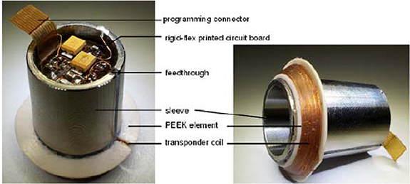
Figure 7. THR sensing system to measure vibration showing the sensing system positioned within a titanium sleeve and the transponder coil wrapped around a PEEK element. 2013 ©, International Frequency Sensor Association (IFSA). All rights reserved.
Download figure:
Standard image High-resolution imageAll three research groups [44–46] that investigated telemetric VA were able to verify their sensing systems and produced similar vibrational response data to [32,37–41].
2.2.2. Acoustic emissions (AEs)
AE is the phenomenon of energy release, in the form of acoustic (elastic) waves, as a result of a solid material undergoing irreversible changes in its internal structure such as crack propagation, phase changes and dislocations within the material [47]. The stress waves generated propagate to the materials surface (figure 8) where they can be recorded by sensors, typically piezoelectric. Key parameters can then be derived including rise time, maximum signal amplitude, signal duration, signal energy and peak counts. If multiple sensors are present the timings of the waves arrival at the materials surface can be used to triangulate the point of origin and hence the location of the defect.
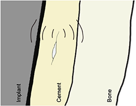
Figure 8. Crack propagation in the bone cement will release acoustic waves which will travel to the surface of the bone or implant and can then be detected.
Download figure:
Standard image High-resolution imageOne of the earliest examples of using AE to determine the occurrence of implant loosening was conducted in 1989 by Sugiyama et al [48]. They used an AE technique to investigate the effect torsional load has on femoral stem loosening and compared three cementing techniques including combinations of canal irrigation, manual insertion, and vacuum mixing combined with pressure injection. They concluded that the most successful cementing technique (as measured by reduced AEs) was pressure injection and vacuum mixing of the cement, however some AEs were still detected suggesting that even the best cementing technique was prone to failure when torsional loading was applied [48].
Other studies [49–51] have also assessed whether AE can be related to cement-bone debonding. These studies used a similar approach; placing piezoelectric transducers positioned on the surface of, or embedded into, the femoral stem. All noted the discontinuous nature of the cumulative AE events and attributed this to the propagation of a crack or coalescence between a main crack and a microcrack. Additionally, AE waveforms related to cement cracking have higher energy, longer signal duration and shorter rise times. Furthermore, work conducted by Rowland et al [52] demonstrated that AE monitoring could be used for the detection of excessive wear. They had two AE sensors positioned on the top and bottom fixtures of a five-station wear rig and noted that one of the stations showed two repeating signals of 57 dB and 66 dB amplitude. This was associated with higher volumetric wear and a subsequent inspection of the implant components showed evidence of wear that was not seen in the other stations.
Ruther et al [53] developed a novel detection technique they termed magnetic oscillator, that uses elements of AE sensing. The sensing process begins with an external coil exciting the ferrous head of the oscillator. The oscillator then hits the membrane inside the implant and the impulse generated by this contact is dependent on the material adjacent to the membrane. For example, close bone contact, indicative of successful osseointegration, would mean there would be a lower deformation energy and reduced spring dampening. This could be measured by a 2nd external detection coil measuring the velocity of the oscillator or by recording the resulting AE generated by the oscillator contacting the membrane. A mock-up of how the system could be used clinically, a cross section of an instrumented implant and magnified views of the oscillator, is shown in figure 9.

Figure 9. Mock-up of how the novel magnetic oscillator system could be used clinically, a cross section of an instrumented implant and magnified views of the oscillator. © (2011) IEEE. Reprinted, with permission, from [29].
Download figure:
Standard image High-resolution imageRuther et al [54] assessed this concept in an in vivo rabbit model. Three different implant surfaces were used to induce various levels of osseointegration. Over the 4 weeks of implantation the AE changed with loosening of the implants (defined by the low axial pull-out strength of the implant) showing a continuous increase in central frequency. Ruther et al propose a novel solution for a non-destructive in vivo assessment of implant loosening, this required no embedded electronics or telemetry systems and has the potential to provide localised measurement of osseointegration. However, to cover the full surface of the implant the concept would likely require extensive modification to the prosthesis and the addition of the oscillators would potentially complicate the manufacturing process.
2.2.3. Eddy current
An Eddy current sensor uses a sensing coil supplied with an alternating current to create a magnetic field (primary field). If a conductive material intersects the primary field, a magnetic field will then be induced within the conductive material (secondary field), causing a change in the impedance of the coil. This change in impedance can then be detected and related to the distance between the sensing coil and conductive material.
Khoke et al [55] examined the efficacy of implanting Eddy current sensors within the positioning holes left after total knee arthroplasty with the aim of detecting tibial component micromotions. Mohammadbagherpoor et al [56] assessed the use of an Eddy current proximity sensor with a 10 mm diameter solenoid coil. Their simulated and experimental work showed that they were able to detect the micromotions of a 10 mm CoCr rod with a 100 µm resolution at a distance of 20 mm. Although, an Eddy current sensing coil would enable noncontact sensing of micromotions, it remains relatively under-developed and there are potential concerns of factors such as sensor migration over time with any changes in bone morphology.
2.3. Summary
Since 1966 less than 100 patients have been reported in literature to have received an instrumented hip implant and had in vivo measurements recorded. Biomechanical and thermodynamic measurements, and the assessment of implant fixation have been the predominant focus in the field of instrumented hip implants. The first instrumented prosthesis to successfully obtain in vivo measurements was implanted in 1966 [11]. From then to the present there have been several successful attempts at using smart hip implants to record measurements in vivo with the most noteworthy being the work conducted by the Orthoload group led by Bergmann. Bergmann's work improved on previous efforts as they were able to measure the 3D load components acting on the stem with minimal changes to the external geometry or features of the implant components. The packaging of the sensing system within a cavity in the stem meant that the components were shielded from the in vivo environment. However, the modifications made to the internal structure to make the hollow shaft (figure 2(b)) will have involved removal of substantial volumes of material which bring significant risks of compromising the integrity of the stem and increased the complexity of the manufacturing process. This is likely why the cavity housing the sensing system was reduced in the later iterations (figures 3(a) and (b)).
VA and tracking the AEs of the components has shown promising results as a method for measuring implant loosening. However, the limitations of this technique may be that pre-existing data of a well-fixed implant would be required as a reference dataset and that excitation from an external shaker is required. Although, there could be potential for a far wider range of indications or phenomena to be detected from examining the vibration response of an implant system for example wear [52]. These techniques are also vulnerable or sensitive to background noise from the environment for example generated by an experimental hip simulator or when in an in vivo environment. However, improvements in data acquisition and processing techniques and advancements in artificial intelligence and machine learning could address these challenges. More recent developments by Sauer et al [46] demonstrate that potting a sensor system within the head of the implant can address many concerns over sensing performance and implant robustness and therefore represent good candidates for clinical use. Furthermore, non-ferrous metals are no longer being used for implant components, and so there will not be electromagnetic distortion caused by the acetabular cup disrupting the wireless communications.
3. Challenges in developing a telemetry system for an instrumented hip implant
The following section will discuss the challenges that need to be overcome to enable an effective in vivo sensing system for use within a THR. These include choice of sensor, biocompatibility and integration within the implant, power, communication, and regulatory considerations.
3.1. Choice of sensor
The choice of sensor is a key challenge in developing a telemetry system for an instrumented implant. The potential sensing applications that have been formulated around the common indications for revision surgery of a THR (as shown figure 1), are summarised in figure 10. The aim being to develop a system that could continuously provide useful data on the performance of the implant and occurrence or progression of the phenomena associated with the indications for revision surgery.
Sensor choice is clearly a complex challenge, but most simply should primarily be driven by the cause or causes of revision for which data is being collected and accordingly the type and complexity of the system required. There are however several additional considerations. Firstly, the implant is likely to be in situ and functional for over 10 years.. So, the information collected upon implantation may well be needed to address questions formulated 10–15 years in the future. So wherever possible the system needs to be future-proofed. Secondly as more data is collected on implant performance it may be that hitherto unknown associations or 'surrogate' measures may be found to link a data output with impending revision. For example, could reduction in activity be a pre-cursor to failure caused by loosening?
Thirdly, the outcomes outlined in figures 1 and 10 are binary in that they focus on revision as an endpoint. It is likely that as more data is collected there will be a more nuanced measure of failure such as degradation of activity or reduced range of motion. These additional factors may modify the primary driver for sensor choice to what sensors or combination of sensors would give the most comprehensive output data.

Figure 10. Graphical representations of potential sensing methods within a THR addressing the common indications for THR revision surgery.
Download figure:
Standard image High-resolution image3.2. Biocompatibility and integration within the implant
Integration of sensing system within an IMD such as a THR has the potential to be beneficial however, it is important that the system does not impede the normal function of the implant nor cause an adverse biological response. This will require miniaturisation of the components to fit the size constraints of the implants as well as careful selection of materials and the mounting, embedding or encapsulation method. The assessment of biocompatibility should require biological evaluation including cytotoxicity testing, examination of the immunological and pathological effect on surrounding tissue and characterisation of the expected degradation of the implant's material over the lifetime of the implant as per the recommendations of ISO 10 993 or other such standards. Furthermore, conventional consumer electronics are designed for a lifetime of 2–5 years whereas the lifetime of an orthopaedic implant is longer 10–15 years and so this is a factor that will need to be considered by medical device manufacturers (MDMs).
Typically, electronic components require protection and shielding from dust, debris, moisture, temperature and salinity that could interrupt their function or cause a degradation in their performance. Electronics implanted in humans must be protected from inner body elements such as cells, proteins, platelets, and chemical gases [57]. Furthermore, electronic components and the substances for the building up of integrated circuits, circuit boards, packaging materials and communication cables are not suitable for implantation. Printed circuit boards (PCBs) consist predominantly of fiberglass and copper foil which are not biocompatible [58, 59], additionally PCB manufacture requires toxic chemical treatments.
Conventional electronics can be used within IMDs but will require encapsulation within a polymer or in a hermetically sealed chamber. Low consistency silicone has been shown to have favourable water absorption, water solubility and surface characteristics for long term implantation when compared to epoxy resin or polyurethane [60]. Chambers or recesses can be manufactured within the bulk material of the implant be it metal, polymer, glass or ceramic and welded or bonded to create a hermetic seal [57]. The hermeticity of the device would need to be assessed before medical device approval.
3.3. Power delivery system
Power supply is vital for the telemetry system of an IMD and the selection affects the proper function of the circuitry and the longevity of the working system. To date, only batteries and inductive power coupling have been used in untethered instrumented hip implants. Power supply still remains one of the most limiting factors of IMDs with the most significant constraints being size and demands of high capacity/lifespan [57, 61].
Sensing systems can be classified as active or passive; active systems require an internal power supply to drive active components such as a microcontroller unit and transducers. Conversely, passive systems do not receive power internally but instead by an external interrogator, whereby, a signal is generated by the interrogator's excitation circuit and sent at radiofrequency to the sensor [62]. A sensing system can include active sensors but have a passive power supply unit such as an inductive charging link.
Batteries can supply consistent levels of electrical energy that is stored in the form of chemical energy. The first use of a battery within an instrumented hip implant was English and Kilvington [12] and then Davy [25]. Many widely accepted IMDs use batteries. Examples are drug pumps, cochlear implants and pacemakers which can have a lifespan of 8–10 years [63].
Lithium ion batteries are preferred owing to their high energy density which can range from 210 mWh g−1 to 440 mWh g−1 [61, 64]. A rechargeable system would satisfy the requirements of an IMD including longevity and power supplied. However, during the process of recharging battery cells temperature can increase significantly and energy capacity is decreased with every recharge cycle. Recharging options are limited, one option would be an ultrasonic source. Ultrasonic transcutaneous power transfer begins with an external transmitter converting electrical energy into acoustic or vibration waves which propagate through the tissue gap to the internal receiver. The piezoelectric receiver then converts the acoustic or vibration energy back to electrical energy [65]. Awal et al [66] conducted an empirical review on the use of acoustic energy transfer for IMDs and found that the efficiency of such systems can reach an efficiency of 45% over a range of 400 mm and typically operated over a frequency range of 35 kHz–30 MHz with a maximum power level being found to be 5.4 W. Although, charging capabilities require additional circuitry [67] thus straining the size constraints of IMDs.
Another option for powering an instrumented hip implant is inductive charging which was first used by Carlson et al [14] an later by other groups [18, 20, 23, 28, 44–46]. An inductive coupling system has been the preferred method of power transfer likely since data can also be transferred inductively.
In the early 1830s, Michael Faraday first discovered the concept of electromagnetic induction, the theory behind the wireless transfer of electrical energy. Inductive power transfer works by passing an alternating current through an 'external' transmitter coil which generates an electromagnetic field which induces a voltage within an 'internal' receiver coil [61, 68]. The voltage can then be converted to direct current through a voltage rectifier and then be used to power a circuit or charge an inbuilt battery or storage capacitor for use at a later time. Factors that can affect wireless inductive power efficiency include resonance/operating frequency, distance, coil alignment, size and number of turns [68, 69]. Inductive power can satisfy the size and energy requirements for an instrumented implant. Theoretically an inductive link power system can be used for an infinite amount of time after surgery thus making them an attractive option for a long term IMD. However, exposure to high levels of electromagnetic fields can be dangerous for patients [67] and if the coils are not properly aligned power transfer efficiency is significantly reduced [70]. Wearing the transmitter coil system can be uncomfortable for patients, possibly limiting their ability to complete activities of daily living and limits the acquisition of data over prolonged periods of time [67, 71].
A promising alternative technology is the use of energy harvesting to convert the mechanical energy from joint motion into electrical energy for powering implants. The concern is whether the joints low frequency movement (typically <1 Hz whilst walking) would be sufficient to generate the required power. Unlike conventional sources of mechanical energy, movements can be infrequent and inconsistent and so traditional power management and battery charging systems will be unsuitable. Silva et al [72] developed a hip prosthesis with three separate power generators including a translation and rotation based electromagnetic generator and a piezoelectric generator powered by a ceramic diaphragm located in the hollow femoral head, shown in figure 11. Each generator had an individual power conditioning circuit that fed into the main ultracapacitor energy reservoir, so the implant could function once the generators begin to produce enough energy, or the energy can be stored. Once a predetermined voltage had been reached within the ultracapacitor the energy stored within was delivered to the IMDs telemetry circuit. Other attempts at developing energy harvesting systems for a THR have similarly used a linear electromagnetic generator [73] and piezoelectric transducers [74].

Figure 11. Hip prosthesis with three independent power generating systems. Reprinted from [72], Copyright (2013), with permission from Elsevier.
Download figure:
Standard image High-resolution image
3.4. Data transfer system
Wireless communication would be a necessity for the telemetry system of an implantable medical device, particularly in a deeply implanted orthopaedic implant. Wired communications were used in the first iterations of instrumented implants but are not a viable option as they would induce unnecessary pain or discomfort to the patient and pose an infection risk. A wireless connection would also better enable continuous data collection without causing inconvenience to patients. In which case designers will have to consider data transfer rate, range, permittivity through human tissue and the additional size and power consumption constraints.
The choice of the wireless communication system will depend on what data needs to be transferred to or from the implant, and when. If the system's output only involves small amounts of data (e.g. ID of the patient and implant or single measurement of blood glucose or temperature) or if the frequency of measurement is low (e.g. one sample per hour) this places lower demands on a real time data transfer system. Similarly, if the collected data can be stored or processed locally (in the implant), it can be uploaded at the convenience of the user, without requiring a continuous telemetry system in place. One such low capacity yet versatile data transfer method could be radio frequency identification (RFID), which is being seen in warehouse inventory tracking, pet identification, contactless payments and tracking marathon runner times.
A RFID system consists of a transponder or tag, a reader or interrogator, accompanying antennas to enable communication through radio frequency (RF) and software that controls the system and manages the data [75]. The tags will have a chip that stores the identification data or electronic product code. Tags can be active, powered by a battery and favoured for their increased range, or passive, powered by the reader's signal and favoured for their low cost (<10 cents) [76].
RFID technology is used to track items and store low levels of data so, could be used to identify medical devices once they have been implanted and include data on the make and model of the implant, reasons for the intervention, the surgeon who completed the procedure and details of the surgical approach. One such company addressing this is Ortho-tag in collaboration with the University of Pittsburgh. Ortho-tag was developed to provide a non-invasive, battery less and wireless method of identifying an implanted orthopaedic device. The system consists of a RFID chip embedded within an implantable tag and a 'touch probe' that uses transcutaneous near field communication to power and communicate with the tag from outside the body [77]. Orthotag claim their system is capable of storing information on an IMD, information which could include x-rays and patient medical records [78].
An enhancement to a RFID system, that could be beneficial in orthopaedic devices, is passive or battery-less sensing capabilities, such systems are known as computational RFIDs (CRFID) [76]. Sample et al [79] achieved this with their wireless identification and sensing platform (WISP) which could both receive power and communicate data to a wireless RFID reader. They showed the efficacy of their WISP by integrating sensors such as temperature, ambient light, rectified voltage, and orientation. Other groups have looked at the possibility of using CRFID systems within IMDs including pressure sensors for orthopaedic implants [80] and blood glucose sensors for continuous blood glucose monitoring [81]. Ortho-tag suggest that their system can feature sensors for the in vivo measurement of pH and temperature to indicate infection in the tissue surrounding an implant [78].
However, past in vivo sensing systems have been used to record real time load and vibration data at frequencies >1 Hz which required data transfer systems with higher data transfer rates. The predominant method used in the majority of past instrumented hip implants has been inductive data transfer with [28, 44–46] all using inductive coupling data transfer and Bergmann et al [28] having a combined power and data coil. Nikola Tesla was the first to realise that electrical energy, and so data, could be transmitted wirelessly between two inductively resonant coils [82]. Inductive power transfer can reach a data transfer rate of up to 100 Mbps at a range of 6 cm outside the body [83]. However, as well as the aforementioned limitations of using inductive coupling for power transfer, when being used for data transfer an inductively coupled system is susceptible to interference from nearby electromagnetic fields [57, 83].
These limitations lead many medical device companies to use, antenna based, RF transceivers for wireless communications between an IMD and external unit. The IMD is equipped with an antenna that when fed with a signal radiates electromagnetic waves through the body to an external receiver [84]. The RF spectrum ranges from 3 KHz to 300 GHz; between 30 MHz and 400 MHz is the human body's resonance range where specific absorption rate is at its highest [85] meaning that RF waves can penetrate the furthest into the body. Therefore, a transceiver operating around this frequency range would be desirable for a deeply IMD.
In 1999, the increased use of RF systems in IMDs lead the Federal Communications Commission (FCC) standardising the Medical Implant Communication Service (MICS), to the RF band 402–405 MHz. In 2009 the FCC upgraded the MICS to the Medradio service which included two additional 'wing bands' thus extending the band to 401–406 MHz [83, 84, 86]. Global medical device companies have manufactured their own remote monitoring systems using MICS: Biotronik Home Monitoring® (FDA approval 2001), Medtronic Carelink® Network (FDA approval 2005) and Merlin.net® Patient Care Network (FDA approval 2007) [87].
Another option for wireless communication is Bluetooth or Bluetooth low energy (BLE). Bluetooth is a standard for wireless exchange of data operating at a RF of 2.45 GHz. At this frequency the radio waves will have a penetration depth of approx. <4 cm in fat and <2 cm in skin and muscle [88, 89]; however, the higher frequency means that BLE has a far higher data transfer rate, up to 2 Mbps [90].
To date Bluetooth has not been used in an instrumented hip implant but has seen use in other IMDs. The Confirm Rx ICM (Abbott, Ill, US) is the first Bluetooth enabled and smartphone compatible implantable cardiac monitor to have received FDA approval in Oct 2017 [91]. In July 2018 the world's first pacemaker with Bluetooth technology (Azure Bluesync pacemaker, Medtronic, Db, Ireland) was implanted [92]. Bluetooth is widely used within consumer electronics with many personal devices being Bluetooth enabled. Based on the early adoption of Bluetooth enabled IMDs it is reasonable to assume that devices of a similar nature will become more widespread throughout the medical sector. However, for application within the hip joint the low penetration of 2.4 GHz RF waves will make Bluetooth an unfeasible option. An alternate solution to this is a dual band radio repeater that can receive radio signals at one frequency and retransmit at another. Kiourti et al [93] configured an on-body antenna to receive transmissions from an IMD in the MedRadio band 401–406 MHz and retransmit the received data to an external device in the ISM band, 2400–2480 MHz. This approach would also improve energy efficiency as transmitting low frequency waves is far more energy efficient therefore reducing the power consumption of the IMD's telemetry system.
3.5. Regulatory considerations—medical device approval
Europe and the US are the largest global markets for medical devices. To market their devices within these territories MDMs need to comply with the regulations laid out by the European Commission in their Medical Devices Regulation to achieve a CE mark or be approved by the US Food and Drug Administration, respectively.
An in vivo sensing system for use within a THR will be a class III (implanted) medical device and so will require extensive pre-clinical and clinical testing to provide evidence of its efficacy and safety before it can be approved. The same will be required when following the FDA's pre-market approval (PMA) pathway for new medical devices when entering the US market.
If integration of the telemetry system has required modification of the implant, then new approval will be required for the implant. If a pre-existing implant has been used, then the FDA's 510 (k) pathway would provide a shorter route to approval. Nevertheless, these additional regulatory hurdles will mean further costs, risks and inconvenience for the MDM. Whereas, if the sensing system is able to integrate with the implant without changing function or geometry then approval requirements may be more easily met. Furthermore, the safety of the in vivo sensing system, and accompanying telemetry, should not be considered in isolation and interactions with the implant should also be considered. Attaching or embedding the sensing system could lead to corrosion, generation of wear particles and there is the risk that the system will move from the intended position or become separated from the implant. These implications should also be considered for the entire lifetime of the implant even if the telemetry system becomes inactive or stops working.
In a 2018 FDA public workshop [8] it was highlighted that care should be taken to go beyond physical characteristics associated with pre-clinical testing, such as biocompatibility, sterilisation, electrical and mechanical performance, and sensor accuracy and repeatability. For in vivo sensing systems, regulatory considerations should also encompass validation of the metrics produced and the level of evidence required should be dependent on how the data will be used, for example if the sensor is delivering a treatment or providing a diagnosis of a potentially life-threatening condition. In either scenario the wrong result would cause harm to the patient or be life threatening.
3.6. Regulatory considerations—cybersecurity
In 2017, the global WannaCry cyber-attack was estimated to have cost the NHS £92 m, £19 m lost output and £73 m in IT costs the majority being spent in the aftermath [94]. A study conducted by Clearswift revealed that in the UK, 67% of healthcare organisations suffered a cybersecurity incident in 2019 [95]. The risk of cybersecurity related incidents within healthcare are increasing as more medical devices have wireless connectivity and are joining the internet of things.
In the past there was concern over malicious cyberhackers gaining unlawful access to a patient's IMD and causing harm to the patient. In a 2013 interview, Former Vice President Dick Cheney revealed that in 2007 he had the wireless connectivity of his pacemaker disabled to avoid the possibility of an assassination attempt [96]. Halperin et al [97] were the first research group to show that an IMD could be infiltrated and patient data and safety put at risk. In 2011, amateur hacker Barnaby Jack demonstrated live on stage, at the Hacker Halted conference in Miami, how he could hack into an insulin pump and deliver a fatal dose to the user [98, 99]. The following year Jack performed a similar live demonstration in which he hacked into a pacemaker and commanded the device to deliver a deadly voltage surge of 830 V [99, 100]. Although theoretically possible it is highly unlikely that attacks like these would ever occur. Dick Cheney's unique public figure status meant that he was at a high risk and so every precaution was taken to guard him against possible attacks. Additionally, hacking into a user's pacemaker would require the attacker holding 'suspicious' specialised electronic equipment close to the user for an extended period of time therefore making it hard for the attack process to be scaled and in general there are far easier, more effective and profitable ways to cause harm or steal a person's data [101]. To-date there is no evidence of cases where a patient's IMD has been hacked with malicious intent. Though there have been device recalls [102, 103] and safety communications issued by the FDA [104–107] where cybersecurity vulnerabilities were cited.
Cardiac and drug delivery devices, such as pacemakers and insulin pumps, carry higher levels of risk whereas, a non-active in vivo sensing system will carry less risk as it only provides diagnostic capabilities so cannot have a 'physical effect' on the patient or user. However, if a smart implant capable of in vivo sensing is realised, and intended to be used clinically, it is likely that the device would include or even require functionality to store data on the patient and their medical history. This data could be a potential target for malicious cyber hackers as medical records are worth more than a credit card number or bank details when sold on the dark web [108, 109]. Although there will be an inherent risk of an IMD being hacked, this is not the only component of cybersecurity that should concern MDMs and regulatory bodies instead, the majority of medical device cybersecurity should be preventing accidental cyber harm and, making sure the system is robust to the unknown and unexpected [110].
In 2013, the FDA released a safety communication that warned MDMs, hospitals and users that cybersecurity breaches could affect the proper function of an IMD [111]. Building upon this the FDA issued the 'Content of Premarket Submissions for Management of Cybersecurity in Medical Devices' guidance document [112], and updated in 2018 [113]. The guidance encourages MDMs to consider cybersecurity measures during the entire lifecycle of the device and provides details on the documentation required for the PMA submission with regards to cybersecurity. Additionally, in 2019, the Medical Device Coordination Group released 'guidance on cybersecurity for medical devices' [114] which provides recommendations to MDMs on how to satisfy the requirements laid out in the MDD that relate to cybersecurity.
4. Conclusion
The number of THRs are increasing, complication and revision rates whilst low are still at undesirable levels. An in vivo sensing system with telemetric capabilities would be beneficial as a means of gathering valuable data on the implant's function and the condition of the surrounding tissue. This data could be used to verify in-silico and in vitro studies, inform improvements in implant design and surgical technique, and guide postoperative care. If real time condition monitoring is achieved along with intelligent recognition of adverse events and deviations from a patient's normal function, then such systems could provide advantages including remote patient monitoring, improved accessibility to healthcare and continuous as oppose to episodic and largely unnecessary assessment and early detect of problems.
Since the implantation of the first instrumented hip implant in the 1960s less than 100 patients have received an instrumented implant capable of in vivo sensing. These implants have measured biomechanical metrics, including force and moments and temperature. The data gathered has helped progress understanding of how a THR functions in vivo and so informed improvements in implant design and surgical technique. However, force, moments and temperature measurements are currently not sufficient to deduce early indications for revision surgery. However, they are important metrics and may still be required in a sensing system for use in a smart THR capable of condition monitoring and intelligent feature recognition. Other experimental work has looked at measuring levels of implant loosening presumably because loosening is the most common indication for revision surgery in THR and indeed other orthopaedic implants. This work has shown potential but until it can be shown that the diagnostic accuracy and reliability is matched to standard radiographic methods then, clinical translation will not be a possibility.
Widespread adoption of smart instrumented THRs and IMDs will not be realised until several key challenges have been overcome these include: what sensing method is used, biocompatibility and integration within the implant, power delivery, communication, and regulatory considerations. Additionally, product liability is also a limiting factor within the field of IMDs as MDMs will not want to take on the additional risks associated with developing and marketing such technology without measurable benefits either in improved outcomes or reduced costs but also to the wider healthcare system. Also, the expected lifetime of a THR is >15 years whereas the lifetime of common consumer electronics such as a smartphone is <5 years (whilst also receiving regular software updates). This will need to be considered by MDMs when designing the hardware and software of the IMD. Smart implantable medical devices, such as pacemakers and insulin pumps, are becoming more accepted and widely used as clinical interventions. Furthermore, advances in technology such as wireless power and telemetry systems, suggests that the development and eventual adoption of an instrumented hip implant, capable of real time condition monitoring, is imminent.
The successful introduction of technology outlined in this review would not only benefit the patient, but it would also enable clinicians to base decisions on more objective quantitative data This would potentially obviate the need for follow-up clinics for all patients thereby reducing hospital workload and hence costs which would benefit the payer whether they are a government or an insurance company.
Data availability statement
No new data were created or analysed in this study.
Acknowledgment
Oliver Vickers studentship was funded by the EPSRC Centre for Doctoral Training in Tissue Engineering and Regenerative Medicine - Innovation in Medical and Biological Engineering (Grant number EP/L014823/1) and further research funding was from the Engineering and Physical Science Research Council (EP/R003971/1).