

Abstract
Direct air capture (DAC) can provide an impactful, engineered approach to combat climate change by removing carbon dioxide (CO2) from the air. However, to meet climate goals, DAC needs to be scaled at a rapid rate. Current DAC approaches use engineered contactors filled with chemicals to repeatedly capture CO2 from the air and release high purity CO2 that can be stored or otherwise used. This review article focuses on two distinctive, commercial DAC processes to bind with CO2: solid sorbents and liquid solvents. We discuss the properties of solvents and sorbents, including mass transfer, heat transfer and chemical kinetics, as well as how these properties influence the design and cost of the DAC process. Further, we provide a novel overview of the considerations for deploying these DAC technologies, including concepts for learning-by-doing that may drive down costs and material requirements for scaling up DAC technologies.
Export citation and abstract BibTeX RIS

Original content from this work may be used under the terms of the Creative Commons Attribution 4.0 license. Any further distribution of this work must maintain attribution to the author(s) and the title of the work, journal citation and DOI.
1. Introduction
'Every bit of warming matters, every year matters, every choice matters.' IPCC Chair Hoesung Lee emphasized the critical need for deliberate action in his opening statement during the 2018 Talanoa Dialogue [1]. Climate change is moving quickly—are we moving fast enough? Through the Paris Climate Agreement, nearly all countries have committed to reducing the global temperature increase to 2 °C above preindustrial levels, with an added goal of a 1.5 °C reduction. As of 2020, the global mean temperature has already increased 1 °C. To meet our climate goals, 10 billion metric tons (referred to as tonnes from herein) per year (GtCO2yr−1) must be removed globally by 2050. After 2050 and thereafter, 20 GtCO2 yr−1 must be removed [2]. These reductions do not include emissions avoided by decarbonization, rather CO2 directly removed from the atmosphere. Meeting climate goals calls for careful demand management, deep decarbonization, and the deployment of negative emissions technologies (NETs). No longer can NETs be a last resort option—they must be used to offset sectors that are hard to decarbonize and to repay the debts held by the planet's carbon reservoirs.
No one NET can feasibly reach the scale necessary within the century, so deployment of a variety of NETs is necessary. Direct air capture (DAC) is one of the many NETs that can be used and has the potential to be a major player. Today DAC is removing 1000s of tonnes of CO2 per year [3]. To reach gigatonne scale by 2050 will require annual growth rates of nearly 50%. This paper will review the current state of the DAC field, the challenges of scaleup, and ways to best approach efficient scaleup.
The purpose of DAC technologies is to capture CO2 from the air and produce a more concentrated stream of CO2. The produced CO2 can be utilized in a variety of ways; however, for positive climate intervention, the end-goal is scalable CO2 storage. As the definition of DAC is so broad, there are a variety of promising and developing DAC methods. The two processes furthest along in development are liquid solvent and solid sorbent DAC, which will be discussed in more detail in the following section. Nevertheless, there are many additional pathways to DAC that are not as far along in development. Cryogenic DAC takes advantage of the sublimation point of CO2 to produce solid CO2 from air which may be stored as such or resublimated to produce high purity gaseous CO2 [4–6]. Moisture, or humidity, swing adsorption uses anionic exchange resins to capture and evolve CO2. These sorbents will bind to CO2 in arid conditions and evolve CO2 when in contact with water, which has the potential to decrease energy requirements at the cost of increasing water consumption [7–9]. Voskian and Hatton [10] propose an electro-swing process by which CO2 binds to a polyanthraquinone-carbon nanotube composite upon charging and is released upon discharge, eliminating the need for thermal energy and producing a high purity CO2 stream. Other approaches include the use of intentionally manufactured alkaline feedstocks, such as caustic calcined magnesia (MgO), to capture CO2 from air [11], and the use of an aqueous amino acid solution to absorb CO2, regenerated by crystallization of an insoluble carbonate salt with a guanidine compound [12]. While each of these developing approaches presents a unique opportunity for innovation in the DAC field, the solid sorbent and liquid solvent approaches are furthest along in development which provides a distinctive opportunity to evaluate the state of the technology, as well as their scalable potentials—which comprises the novelty of this review. As such, this review will focus on the solid sorbent and liquid solvent DAC approaches, representing the technologies that are ready for increased deployment today.
1.1. Commercial pathways to DAC
The primary industrial developers of DAC today are Carbon Engineering (Canada), Climeworks (Switzerland), and Global Thermostat (USA). According to the IEA, as of 2019 there are 15 operational DAC plants worldwide [3]. In the US alone, there are plants in advanced development (construction planned to begin in 2022) with the potential to capture up to 1 MtCO2 yr−1 [3, 13].
In the solid sorbent approach, CO2 molecules interact with hierarchically porous 4 materials that can remove CO2 from the incoming gas mixture. Adsorption is highly noted for its efficacy in separating dilute gas mixtures. Solid sorbents can remove CO2 from gas mixtures via weak intramolecular forces called physisorption or strong covalent bonding called chemisorption. The bond strength between a CO2 molecule and the surface of the sorbent may be characterized as the heat of adsorption. In broad terms, physisorption occurs when the heat of adsorption is less than approximately 15 kcal mol−1; chemisorption generally occurs when the heat of adsorption is higher than approximately 15 kcal mol−1 [14]. There are some exceptions to this heuristic in the cases of zeolite-based chemisorption processes. Solid sorbents can be augmented with amine surface functionalization that enhances their interactions with CO2 molecules thus making them more selective towards CO2 [15]. Current research efforts explore a myriad of different support structures to use as solid sorbents for DAC: metal–organic frameworks (MOFs), zeolites, activated carbon, silica materials, carbon nanotubes, porous organic polymers, and carbon molecular sieves.
In the liquid solvent-based approach, gaseous CO2 is absorbed into a liquid solvent, resulting in a CO2-depleted gaseous exiting stream and a CO2-rich liquid exiting stream. Solvent-based approaches typically use structured packing to increase the contact surface area between the gas and liquid phases [16, 17]. In the case of solvent-based DAC with structured packing, the surface area is increased while the gas-side pressure drop is typically decreased. The solvent-based approach requires a strong basic hydroxide solution to absorb CO2 [18]. This is followed by an anionic exchange that ultimately results in precipitated calcium carbonate pellets. The solvent approach to DAC requires high temperatures to recover CO2 from precipitated calcium carbonate. The tradeoff between having a strong capture agent and the required regeneration energy is not unique to liquid solvent DAC. However, the extreme dilution of CO2 in air requires that a strong base is used for adequate separation, which further drives the high energy requirement of this separation.
1.2. Base strength and impact on CO2 capture
There are inherent material differences between the contactors of solvent and solid sorbent-based separation processes. The flux of CO2 is measured in amount of CO2 removed from the atmosphere per unit time and contact area of the separation device. Hence, this parameter may be used to estimate the rate of CO2 removal per unit of contactor cross sectional area. The way in which CO2 is effectively removed through air is through a chemical reaction with a base. The key is to maximize the number of interactions between the CO2 coming in from air and the base chemistry present in the contactor. There are three key, high-level factors for the CO2 uptake in sorbent and solvent materials that must be optimized: (a) the basicity of the sorbent, (b) the loading of the sorbent onto a support structure, and (c) the exposed surface area of the sorbent. Here, we demonstrate that contactor structures with higher specific surface areas per unit volume can use a weaker base to achieve the same amount of capture in a given volume.
In the solvent-based separation process, due to the corrosive nature of bases, the solvent may only be present up to 30 wt%, which limits the number of interactions with CO2. Solid sorbents on the other hand have the benefit of the base being chemically bound to the solid framework of the sorbent such that it is more 'contained' and can therefore be loaded at a much higher weight percent thereby increasing the number of interaction/binding points with CO2.
An additional difference is in the nature of how each of the materials is packed in the contactor. In the solvent case, the solution is pumped through high surface area structured packing material with channel sizes adequately large for liquid to flow, but adequately small to create sufficient surface area to maximize the number of interactions between CO2 and the chemical solvent. This coating of the solution over the packing material also decreases the liquid-phase diffusion resistance of CO2 as it leaves air and dissolves into solution in search of the base with which to react. Solid sorbents on the other hand, due to their hierarchical pore structure, have a combination of micro and mesopores, which allow for maximizing surface area and facilitating transport, respectively.
Examination of measured fluxes available in the literature [16, 17] reveals the need for a strong base in the case of solvent-based separation of CO2 from air, which in turn leads to a process that ultimately requires calcining carbonate to regenerate the sorbent for multiple cycles. For a strong base, sodium hydroxide (NaOH), the two parameters that have the greatest influence on the flux of CO2 removal from air via the contacting unit are the solubility of CO2 at the gas–liquid interface, represented by the Henry's law constant, and the chemical reaction kinetics of CO2 with the base. The solubility of CO2 in a solution containing NaOH is roughly 3.8 × 10⁻⁴ cm3 mol−1 and the reaction constant of CO2 with NaOH is roughly 8.5 × 106 cm3 mol−1 s−1 [16]. Based on Whitman's Film Theory, this results in a flux estimate of ∼4.1 × 10⁻⁹ mol cm−2s−1 for NaOH. Using these flux estimates, a specific surface area of 210 m2 m−3 for the packing material (Brentwood XF12560 [16]), and assuming transport through a 1 m contactor depth leads to a CO2 loading of 0.52 mol CO2 min−1 m−3 of material, for a 2 M NaOH solvent.
In the case of solid sorbents, amines are a common chemistry for CO2 capture. Based on the work of Sinha et al [19], they measured a loading of CO2 of ∼2.5 mmol CO2 g−1 sorbent over 3000 s. Although these properties vary by sorbent type, they are used here as a representative example. The contactor geometry used in this analysis is a monolith with channel diameter of 625 μms on which 60 μm layers of sorbent are deposited. Each monolith contains 750 000 channels. Using a sorbent density of 500 kg m−3, this gives an overall sorbent density per cubic meter of contactor (including both monolith and sorbent) of 70.7 kg sorbent per m3 of contactor. This leads to an equivalent loading of 3.53 mol CO2 min−1 m−3 of solid sorbent material, indicating that the solvent with a strong base has a loading roughly one order of magnitude lower than the sorbent scenario. This is simply because the solid sorbent has a significantly higher contact area compared to the liquid-coated packing material in the equivalent volume.
These fundamental differences among the solvent versus solid sorbent-based separation processes highlight opportunities for further research and development in this space. For example, work on advanced solvents that would allow the chemistry to be readily available at the gas–liquid interface or that have the ability to coat packing material in a thinner layer would lead to lower liquid-phase diffusion resistance. In addition, advanced packing materials that would allow for a greater surface area could also lead to increased interactions between the base chemistry and CO2. Similarly, there may be an optimization between the base strength and uptake that can be optimized to minimize the system energy requirements.
2. Overview of the current state of liquid solvent and solid sorbent DAC
A representative process flow diagram for the liquid solvent DAC system is provided in figure 1 and consists of two loops: the contactor loop and the calciner loop. In the contactor loop, air is forced horizontally through the long contactor units (roughly 200 m by 20 m by 5–8 m) [2, 16] of which ten units are required to capture roughly 1 MtCO2 yr−1. In more recent designs, the air is pulled horizontally through the packing material by a fan and exits vertically, similar to a cross-flow forced draft cooling tower [13]. In the contactors, a 2 M KOH solution flows vertically through packing material, reacting with the CO2 in air to form potassium carbonates in solution (K2CO3) [17]. After exiting the contactor, the solution is pumped to a central regeneration facility. Here, the K2CO3 undergoes an anionic exchange with calcium hydroxide (Ca(OH)2) in the pellet reactors to form calcium carbonate (CaCO3) and regenerate the KOH solution, which can be pumped back to the contactors. Simultaneously, the pellet reactors also produce larger CaCO3 crystals through controlled precipitation reactions to produce CaCO3 pellets larger than 0.85 mm [17]. The produced CaCO3 is then fed into a steam slaking unit, where heat from the calciner products is used to dry the CaCO3 from the pellet reactors before they are fed into the calciner. In the calciner, the CaCO3 is heated to 900 °C, where it undergoes a decomposition reaction to form calcium oxide (CaO), water and CO2. Currently, the calciner is internally fed with natural gas and oxygen to obtain the required temperature, which results in a gaseous mixture consisting primarily of CO2 and water. The CaO is then fed into the slaking unit where it is hydrated to Ca(OH)2. From here, the Ca(OH)2 can be fed back into the pellet reactors for the anionic exchange. The gas produced at the calciner is sent through a condenser to remove the majority of the water present and the resulting CO2 is compressed.

Figure 1. Representative process flow diagram for the solvent process. Here, green lines represent gaseous flows, blue lines liquid flows and brown lines solid flows. The H2O streams undergo temperature changes throughout the process that are not represented in this simplified diagram.
Download figure:
Standard image High-resolution imageTo capture a tonne of CO2, this process has an energetic requirement equivalent to either 8.81 GJ natural gas or 5.25 GJ natural gas coupled with 366 kWh of electricity. Carbon Engineering estimates the cost of capture for this process to be between $94 and $232 per tonne of CO2 captured [17].
Carbon Engineering is the first commercial entity to pursue solvent DAC technology. They use a potassium hydroxide solvent-based approach to their DAC technology coupled with a calcium caustic recovery loop. In 2015, Carbon Engineering constructed the first pilot-scale DAC plant, in British Columbia, Canada. They dedicated 2019–2021 to designing and constructing a demonstration DAC plant, also in Canada. In 2021, Carbon Engineering aims to finalize engineering designs for a DAC plant in the Permian Basin with Oxy Low Carbon Ventures [20]. The project in the Permian Basin would have the capacity to capture and store up to 1 million tonnes of CO2 per year [21]. Construction of this plant is expected to begin in 2022. Additionally, Carbon Engineering is collaborating with Pale Blue Dot to develop DAC capacities in the UK [22].
Figure 2 provides a representative process flow diagram of the stationary bed solid sorbent DAC process. In this process, air is pushed through the contactor unit by fans and the CO2 adsorbs onto the solid sorbent at ambient conditions. After the solid sorbent is saturated with CO2, or has reached the desired CO2 uptake, the apparatus is switched from adsorption to desorption mode. At this stage, the contactor is closed off from the surrounding environment. A vacuum pump evacuates residual air from the contactor to prevent dilution of the produced CO2 by residual oxygen and nitrogen in the contactor in addition to minimizing amine degradation from air. Previous literature suggests that this vacuum pressure is on the order of 30 mbar [23], and that the vacuum stage can also decrease the temperature requirements for regeneration [24]. Following the vacuum stage, steam is sent into the contactor to heat the material to the regeneration temperature (roughly 80 °C–120 °C) [25, 26]. The steam additionally flushes the released CO2 from the contactors, which is then separated from water in the condenser and sent to compression for subsequent transportation, storage or utilization. Other mechanisms for sorbent regeneration are discussed in section 3.3.

Figure 2. Representative process flow diagram for solid sorbent DAC. The adsorption and desorption processes for the solid sorbent process are performed in batch, with each composed of multiple process steps. Here, green lines represent gaseous flows and blue lines liquid flows. The dashed green line from the contactor to the vacuum pump represents the initial phase of desorption where residual air is removed from the contactor to prevent dilution of the produced CO2 after evolution from the sorbent.
Download figure:
Standard image High-resolution imageClimeworks was founded in Switzerland in 2009 and developed the first working prototype of their DAC technology by 2013. Four years later, they launched the first commercial DAC plant. In 2019, Climeworks opened the first service to offer carbon removal to individual customers.
Climeworks has publicly set a goal of removing 225 million tonnes of CO2 from the atmosphere by 2025, approximately 1% of total worldwide emissions. At an energy consumption of 2000 kWh per tCO2, Climeworks' 2025 goal will require approximately 450 TWh of energy [25]. The capital cost of constructing the Climeworks' Hinwil DAC system, which captures 900 tCO2 yr−1, was $3–4 million; the capital cost is the largest influencer of the levelized capture price of $500–600 per tonne of CO2 [2, 27, 28].
The third commercial DAC venture, Global Thermostat, is based in the United States. Founded in 2010, Global Thermostat currently has two pilot DAC plants with the potential to capture 3000–4000 tonnes of CO2 per year. Global Thermostat has partnered with ExxonMobil to expand their technology into a facility capable of capturing 1 million tonnes of CO2 each year. Their process focuses on using process heat to regenerate the sorbent after capture, with steam near 100 °C up to roughly 130 °C, with the preferred range being 105 °C–120 °C [29]. The capture process is followed by a CO2 collection system for a number of possible applications: dedicated geological sequestration, biofuels, or non-fuel products like fertilizer or construction material. An overview of each commercial company is provided in table 1.
Table 1. Public information on commercial DAC entities.
| Carbon Engineering [17, 22, 30] | Climeworks [25, 27, 28] | Global Thermostat [26, 29, 31] | |
|---|---|---|---|
| Founding year | 2009 | 2009 | 2010 |
| Current scale (tCO2 yr−1) | ∼365 | ∼1000 s | ∼1000 |
| Thermal energy requirements (GJ tCO2 −1) | 5.25 | 5.76 | —a |
| Required temperature of thermal energy (°C) | 900 | 80–120 | Preferably 105 °C–120 °C but up to 130 °C |
| Electricity requirements (kWh) | 366 | 400 | —a |
| Current costs ($ tCO2 −1) | — | 500–600 | —a |
| Projected costs ($ tCO2 −1) | 168–232 first-of-a-kind 94–170b nth-of-a-kind | Target of 200–300 within five years and 100 within ten yearsc | —a |
| Past projects | Pilot scale plant in British Columbia capturing 0.6 t d−1 | 14 commercial DAC plants throughout Europe. First commercial DAC plant capturing 900 tCO2 yr−1 delivered to a next door greenhouse. CarbFix and CarbFix2 Projects | Pilot plant with SRI in Melano Park, CA captured roughly 1000 tCO2 yr−1 |
| Future projects | Industrial scale plant with Oxy Low Carbon Ventures capturing up to 1 MtCO2 yr−1 slated to begin construction in 2022 | Goal to remove 225 MtCO2 yr−1 by 2025 | Two pilot scale plants with the capacity to remove 3000–4000 tCO2 yr−1. Industrial scale plant construction with Exxon Mobil |
aGlobal Thermostat has not made any cost or energy estimates publicly and transparently available. bThe cost range of $94–130 tCO2 −1 reflect scenario D from Keith et al [17]. This scenario represents a system optimized for air-to-fuels, where hydrogen is produced via electrolysis which results in an oxygen byproduct. This eliminates the need for an air separation unit as the oxygen is provided from electrolysis, additionally reducing electricity requirements for the DAC component of the system. cThese costs represent publicly stated cost targets for Climeworks from 2019.
2.1. Energy requirements for DAC
Both the solid sorbent and liquid solvent DAC approaches require roughly 80% thermal energy and 20% electricity for operation [32]. This is not an arbitrary percentage as both DAC approaches must optimize between a multitude of parameters. In both systems, the thermal energy demand results from the regeneration of the sorbent and the evolution of the previously bound CO2 compounds. For the solid sorbent approach, the electricity requirements result from the contactor fans, which are required to overcome the system pressure drop, and the vacuum pumps, which remove residual air from the contactor during regeneration [2]. The liquid solvent system requires electricity for the contactor fans—also required to overcome the system pressure drop—as well as the pellet reactors, steam slaker and filtration units [17]. Both approaches must optimize between the pressure drop across the contactor and the amount of CO2 removed from the inlet air stream. This optimization determines parameters like the electricity required to power fans to overcome this pressure drop.
More specifically, the sorbent DAC process has been reported to have thermal energy requirements near 6 GJ tCO2 −1 and electricity requirements at roughly 1.5 GJ tCO2 −1 [25, 32]. Sorbents requiring lower regeneration energies have been estimated to reduce the thermal energy requirements on the order of 3 GJ tCO2 −1, with some sorbents claiming low regeneration energies near 1 GJ tCO2 −1 [33–35]. The solvent process has been reported to have thermal energy requirements ranging from 5.25 to 8.1 GJ tCO2 −1, primarily depending upon the extent of heat integration from the calcination process, and electricity demands of 1.3–1.8 GJ tCO2 −1, which result from variations in the packing material and contactor configuration used in the liquid solvent DAC process [17, 18, 36].
Overall, the energy demands of the solid sorbent and liquid solvent systems do not differ greatly from one another. However, the quality of thermal energy required for the DAC processes differs greatly. The solid sorbent system requires thermal energy on the order of 80 °C–130 °C, which may be met via industrial waste heat or other sources of lower quality thermal energy [25, 29, 37, 38]. These temperatures are also well within the temperature range of commercial industrial heat pumps, which could upgrade lower-quality waste heat for this purpose [39]. The use of heat pumps requires additional electricity and reduces the thermal energy requirements, which increases the share of electricity in the DAC system beyond 20%. Because of the high coefficient of performance of heat pumps, this would substantially lower the electricity consumption compared to an approach using resistive heating. Conversely, the liquid solvent system requires heat near 900 °C, which is required for the decomposition of CaCO3 into CaO and CO2 [17]. Thus, solid and liquid systems are most efficiently paired with different thermal energy sources. In addition to efficiency, the relative cost and greenhouse gas emissions of those energy resources are also an important factor [40].
The distribution of electricity and thermal energy requirements for DAC are similar to those of petroleum refineries. In fact, refineries also exhibit a 20% electricity, 80% thermal energy breakdown for their operations [41]. The electricity requirements for refining include energy for pumping, motors, and instrumentation where the thermal energy requirements primarily include steam production and process heating. Both the breakdown of thermal energy and electricity, as well as the operations requiring this energy closely mirror the DAC process. In this sense, DAC can be viewed as a 'refinery for the sky.' Across the U.S. refineries use roughly 3000 000 billion BTU of energy per year, which is equivalent to roughly 880 TWh yr−1. Assuming the same amount of energy was allocated towards DAC and that each DAC facility requires approximately 300 MW of consistent energy to capture 1 MtCO2 yr−1, the same amount of energy could be used to capture 370 MtCO2 yr−1. This illustrates both the feasibility and the challenge of deploying DAC at an industrial scale from an energy standpoint. Additionally, if the energy consumption of DAC can be reduced through process improvements or new designs, this amount of energy could be used to capture correspondingly larger amounts of CO2.
2.2. Modularity
The two DAC approaches considered in this review also vary in their degree of modularity. Modularity refers to the ability of the system to be partitioned into smaller units, where engineered systems, such as DAC, can have varying degrees of modularity [42]. A modular unit can be mass produced and can rapidly implement improvements to design or manufacturing [43]. Modularity is closely related to the minimum feasible scale at which a plant can operate. The solid sorbent DAC approach exhibits greater modularity than the liquid solvent approach. Specifically, in the Climeworks approach, the contactor configuration for the solid-sorbent based process is segmented to allow for individual unit regeneration. A single contactor unit can capture roughly 50 tCO2 yr−1 [25, 44]. To scale, multiple contactor units can be added to the system. In the Global Thermostat approach, the first pilot plant had a capacity of 1000 tCO2 yr−1, with containerized modules operating in the range of 1000–4000 tCO2 yr−1 [31].
The liquid solvent approach does not exhibit the same partition-based modularity as the solid sorbent approach, due to the highly integrated nature of the system, in which the contactors feed CO2-saturated solution to a central regeneration unit. Consequently, the minimum feasible scale of the system is substantially larger than that of solid sorbent approaches. The pellet reactor and air contactor used in the liquid solvent approach can be scaled down to achieve minimum capacities of roughly 10 ktCO2 yr−1, with capital costs roughly consistent up to 100 ktCO2 yr−1 [17]. However, the liquid solvent system experiences significant economies of scale above this point due to the larger process equipment such as the calciner and slaker, reaching an economic optimum at approximately 1 MtCO2 yr−1 [17]. In general, this provides an advantage for large-scale operation. It is important to note that the solvent system does exhibit some degree of modularity as the same system components can be used to construct repeated solvent systems. Additionally, the system partitions the operations of the DAC plant by function, which is another facet of modularity more closely aligned with product architecture [45].
3. Liquid solvents and solid sorbents: properties and processes
For solvent-based DAC, a benchmark example of the hydroxide case is the use of KOH in water. In aqueous solution, KOH dissociates into ionic K+ and OH−. After coming into contact with a dilute stream of CO2, the aqueous phase produces K2CO3. The stoichiometry of K2CO3 reveals that two KOH molecules are required to separate one CO2 molecule. The second primary approach to DAC is the solid sorbent-based chemically functionalized with amines. Current research interests are focused on developing materials with the capability to uptake CO2 under optimal conditions, while being economically feasible at the industrial scale. Solid sorbent options include materials with affinities for CO2 and materials with surface functionalization purposed for CO2 capture: materials currently under investigation include MOFs, activated carbon, silica gels, cellulose, zeolites, and carbon nanotubes.
3.1. Diffusion and chemical kinetics
Each of the DAC approaches utilizes distinct kinetics to effectively separate CO2. Current solvent DAC technology is limited by fast pseudo first order kinetics 5 and is dependent on the concentration of CO2 in the gas phase. In this system, four steps must be considered to adequately characterize the system: (a) gas phase diffusion, (b) diffusion across the gas–liquid interface, (c) liquid-phase diffusion, and (d) chemical reaction. Gas phase diffusion refers to the diffusion of CO2 through air until meeting the gas–liquid interface. Once at the interface, the CO2 will diffuse through the gas–liquid interface where the concentration of CO2 at the interface is determined from Henry's law. In general, the lower the dimensionless Henry's law constant 6 for a given solvent, the higher the interfacial concentration of CO2.
Once the CO2 is in solution, it diffuses through the bulk liquid medium until it finds a solvent species to react with. At this point, the CO2 reacts and is essentially captured by the process. Therefore, designing an effective solvent DAC system requires knowledge of gas and liquid phase diffusion, solubility of CO2 into the solvent and the reaction kinetics of the system [14]. When comparing between solvents, which are composed primarily of water, the reaction kinetics become increasingly important as the diffusion resistances are very similar. However, when comparing between solvent- and sorbent-based DAC systems, the diffusion resistances and timescales become increasingly important as there are more significant variances in the diffusion mechanisms between the two technologies.
To create solvents that react more quickly than those that exist today, their must be innovations that work to develop methods to overcome or limit liquid-phase diffusion resistance. In other words, innovation could create ways to enhance the kinetics such that CO2 uptake in the solvent occurs under the regime of instantaneous reaction as opposed to fast pseudo first order. The conditions for an instantaneous reaction for the solvent approach to DAC include: instantaneous enhancement factor 7 in the lower range, the reaction constant is typically in greater than or equal to 1010 cm3 mol−1 s−1 and the liquid phase mass transfer coefficient is less than or equal to 10−3 m s−1 [46]. Biomimetic catalysts, such as carbonic anhydrase, have been shown to hydrate and dehydrate CO2 orders of magnitude faster than amines or water and could prove useful to accelerating the kinetics of CO2 solvation [14]. Currently, no materials experience a reaction constant of greater than or equal to 1010 cm3 mol−1 s−1 but current research interests are working towards this goal. If this system could achieve instantaneous reaction, the DAC system would be comparable to a more CO2-concentrated flue gas mixture with respect to CO2 flux [46].
The kinetics for the solid sorbent case are highly dependent on the characteristics of the sorbent substrate and functionality, as well as the gas phase concentration of CO2. Adsorption is primarily dictated by external and internal diffusion resistance. The external resistance is characterized by the diffusion through a thin layer of fluid which facilitates the mass transfer of the system. Here, the thickness of this fluid boundary is critical in determining the mass transfer limitations for the sorbent [47]. Internal resistance includes internal diffusion at the micro, meso-, and macro-pore level and is a large consideration for the kinetics of the overall system. The micropores and mesopores experience surface and capillary forces with CO2 molecules, respectively. The macropores do not usually experience intermolecular forces, they facilitate the bulk fluid flow of the system. For the solid sorbent approach to DAC, it is important to consider Knudsen diffusion, where the fluid to surface forces overtake the fluid to fluid forces.
3.2. Heat transfer properties
The heat transfer for the solvent approach is typically much more favorable than that of the solid sorbent case. The absorption of CO2 into the solvent is an exothermic process, becoming less effective with rising temperatures and making heat management an important consideration. Due to the dilute nature of CO2 in the atmosphere and the relatively large channels in commonly used structured packing material, the heat generated may not be significant. After absorption, the solvent needs to be regenerated for future capture. The heat capacity of the solvent is an important parameter when considering direct temperature-based regeneration of the solvent, similar to the methods employed for point source CO2 capture. The solvent heat capacity is approximately equal to the heat capacity of water because it is the primary component of the solvent. For example, the specific heat capacity of water is 4.2 J g−1 K−1 and is roughly representative of a generic solvent in solution. Here, the relatively high specific heat capacity indicates that more heat will be required for a directly heated regeneration process. Therefore, directly heating the solvent for regeneration is not used in current iterations of solvent DAC technologies. Since solvents tend to have higher specific heat capacities, indicating that they also have higher regeneration energy requirements, processes have been developed to regenerate them without using heat. In the solvent system, once the KOH solution has absorbed CO2, the K2CO3 is combined with calcium hydroxide (Ca(OH)2) pellet reaction where the KOH is restored and calcium carbonate (CaCO3) is formed [17]. This reaction is thermodynamically favorable and eliminates the need to directly heat the solvent. However, further thermal processing of the CaCO3, in the calcination step, is required to produce a pure stream of CO2 for storage and a replenished stock of Ca(OH)2.
In the solid sorbent case, adsorption and regeneration are executed on a cyclical basis. Adsorption is an exothermic process: a sorbent support with a high enough thermal conductivity must be used to transfer the sorption heat away quickly enough to keep the sorbent cool as the temperature can have great effects on the sorbent loading and diffusivity of the system. However, on account of the dilute nature of CO2 in air, the heat transfer to the system via adsorption is slow, therefore this heat dissipation can take place slowly. Once the CO2 is adsorbed to the sorbent surface, heat can be used to release the captured CO2 for collection and regenerate the sorbent for further capture. Typical regeneration temperatures for solid sorbents range between 80 °C and 120 °C, which could be met through the use of waste heat [25].
The specific heat capacities of the sorbent material have a large impact on the energy requirements for regeneration. For example, the specific heat capacity of a generic amine impregnated silica ranges between 1.1 and 1.7 J g−1 K−1 [48, 49]. Additionally, amine functionalized MOF SIFSIX-3-Cu similarly shows a specific heat capacities near 0.72 J g−1 K−1 [50–52], indicating that the energy requirements for its regeneration would be marginally less than the amine impregnated silica. This conductivity is similar to more traditional MOFs: for example, Cr-MIL-101 has a specific heat capacity of 0.62 J g−1 K−1 [53]. This relationship is additionally true for the thermal conductivity of the respective materials, as this illustrates how fast heat can move through them. The thermal conductivity for amine impregnated silica and amine functionalized MOF SIFSIX-3-Cu are 0.2–0.3 and 0.32 W m−1 K−1, respectively [48–52].
3.3. Process sensitivities
Adsorption cycles can utilize temperature, pressure, humidity, or a combination of the three, to facilitate the regeneration and saturation phases. In temperature swing adsorption (TSA), CO2 at a given partial pressure is adsorbed onto the sorbent until it reaches the target capacity. Once the target capacity is reached, the bed is regenerated by elevating the temperature, typically by flowing steam through the contactor. When steam is used, systems will typically require 0.2–0.4 kg steam per kg of CO2 [54]. TSA systems are very sensitive to changes in temperature: a slight increase in temperature will lead to a large decrease in the concentration of CO2 in the sorbent bed proportional to the van't Hoff equation 8 .
Adsorption cycles can also be controlled by manipulating the pressure element in an adsorption bed: pressure swing adsorption (PSA). In a PSA system, CO2 is adsorbed onto the bed at an elevated pressure (>1 bar) until the target capacity is achieved. To regenerate the CO2, the partial pressure of CO2 is lowered by reducing the total pressure in the bed to a pressure lower than the adsorption pressure, but greater than 1 bar. Lowering the total pressure of the bed releases adsorbed CO2. PSA systems require little time to complete a cycle: loading, depressurizing, regenerating, and repressurizing. The capital cost for PSA systems is increased due to the handling of pressurizing gases. Vacuum swing adsorption (VSA) has been employed to reduce the cost and hazards associated with pressurizing gases. In VSA, CO2 is adsorbed at atmospheric pressure until the target capacity is achieved. To regenerate the CO2, a vacuum is pulled on the system reducing the pressure to <1 bar. While this system does not require high pressures, it does come with the costs associated with industrial vacuum use. Humidity or moisture swing adsorption can also be used to control the regeneration stage of the solid sorbent system. In this configuration, the sorbent used favors the adsorption of water as opposed to CO2, such as anionic exchange resins [7, 9]. Therefore, in arid environments the sorbent uptakes CO2 until it achieves the target capacity. The sorbent is then regenerated by introducing water to the system as liquid water or water vapor either at ambient conditions or under a partial vacuum [8].
For existing solid sorbent DAC processes, a combined temperature–vacuum swing adsorption (TVSA) process is used. In this system, adsorption occurs at ambient conditions (temperature, pressure). Once the system reaches the target capacity, it is shut off from the inlet flow and a vacuum is pulled to remove residual air inside the contactor. Following this step, a stream of hot gas is flown through the contactor and decrease the regeneration temperature. This is typically steam, which produces a mixture of CO2 and water for separation in a later stage.
Future DAC designs may incorporate moving bed technology where the sorbent is always in contact with the inlet gas stream. Since fixed-bed technology has been the primary focus of commercial DAC technologies, it is the focus of this section. However, moving bed adsorbers present an opportunity for process innovation and have been documented widely in the literature [47, 55]. Compared to stationary contactor systems, moving contactor systems benefit from reduced pressure drops and increased cycle times but are disadvantaged by their more advanced mechanics.
For the industrial solvent process, the system has been evaluated using a closed packed column configuration, as this is typically employed for solvent-based point source CO2 capture [18]. However, through experimental trials, it has been concluded that a cross-flow design, adapted from cooling towers, may show more promise for CO2 capture at such dilute concentrations, as it is more equipped to handle the large air throughputs required for DAC [16, 17]. In these designs, the air flows horizontally through the contactor, where the liquid sorbent thinly coats a packing material as it flows vertically down. The design of a cross-flow air contactor for this purpose is influenced by the gas-solvent contact, solvent flowrate, and energy requirements. To facilitate gas phase and liquid solvent contact, high surface area packing structures are used. Conventional cooling tower packing structures are usually constructed using stainless steel, but using polyvinyl chloride (PVC)-based packing material reduces pressure drop across the contactor and capital costs. A pulsed method has been proposed to ensure sufficient solvent flowrate and packing structure coverage, while also reducing capital cost [16]. The energy requirements associated with the cross-flow contactors stem from the solvent pumping and fans to overcome the pressure drop across the contactor. It is estimated that these contactors are 20 m high by 200 m long, with a depth between 5 and 8 m, for an annual capture rate 1 MtCO2 yr−1. The depth is directly correlated with the pressure drop across the contactor and the percent of CO2 capture from the inlet air stream, therefore making its influence on total energy requirements for capture complicated.
4. Techno-economics of DAC
There are multiple types of costs associated with DAC and reported in the literature. Specifically, the gross cost of capture and the net removed cost of capture. The gross cost of capture indicates how much the process will cost per tonne of CO2 captured from the air. This indicates the cost at which the CO2 will need to be sold for the process to 'breakeven.' The net removed cost inflates the gross cost of capture to account for emissions resulting from the capture process. In this case, the cost tells you how much you will spend to actually remove a tonne of CO2 from the air on a net life-cycle basis. The gross cost and the net removed cost are related by a factor, x, referred to here as the take-back factor that includes all emissions associated with the DAC process. The take-back factor yields the amount of CO2 emitted from the process, in tonnes, per tonne of CO2 removed from air. For take-back factors greater than 1, the DAC system actually results in positive emissions and the net removed cost is undefined. The relationship between gross cost of capture and net removed cost of capture is given in equation (1)

First, the most important consideration when evaluating a cost analysis are the boundary conditions of the analysis. This includes what equipment is included in the cost and to what extent the facility includes both upstream and downstream processing techniques. A good example of this is the inclusion of CO2 compression, as whether or not compression is included in the analysis varies from analysis to analysis. To compare costs between analyses, it is important that they have the same boundary conditions.
For the estimated costs available in the literature, there are a handful of economic parameters that are important to evaluate to understand where these costs come from, regardless of the system the costs are describing. These parameters define how costs are distributed throughout the system. Particularly, the weighted average cost of capital (WACC) which represents the risk of the investment to investors as a cost of capital that includes both interest on borrowed capital and the investors' expected returns. The higher the risk of a process, the higher the WACC. Jointly, the WACC and economic lifetime are used to calculate the capital recovery factor (CRF) which is used to determine the present value of a series of equal annual cash payments. In other words, the CRF determines the annualized capital cost for the system, indicating a large dependence of the cost per tonne of CO2 captured based on the CRF used in the analysis.
Another costing method used in DAC costing is to use a Lang Factor to take the bare module cost of equipment to a fully installed cost that accounts for expenses both inside and outside battery limits [56–58].
Some process parameters are also consistently important across the solid sorbent and liquid solvent DAC systems, particularly the source and cost of electricity and thermal energy. All energy systems have emissions associated with building, implementing, running, or retiring the system. When using fossil-based electricity or thermal energy, the emissions associated with energy production are typically greater than those of renewable energy resources. These emissions, depending on their magnitude, can offset the processes negativity. Additionally, the cost associated with different energy resources changes regionally which has an impact on the economic viability of the process.
To determine the net negativity and environmental impact of a given DAC process, life cycle assessment (LCA) is also crucial. LCA includes determining the impacts associated with each stage of a DAC process, including material supply, energy usage, process operation, and waste disposal, among others. Impacts in this case include CO2 and other greenhouse gas emissions, among environmental considerations, such as eutrophication and/or fresh water toxicity. To truly evaluate the net negativity of a DAC process, all emissions from materials procured to set up the DAC facility to the end of life of the DAC facility must be included in the analysis [59, 60]. This is known as a cradle-to-grave life cycle analysis and is mandatory to determine if a given DAC system truly achieves negative emissions.
4.1. Techno-economics for solid sorbent DAC
Literature analyses have estimated the per tonne CO2 cost of solid sorbent DAC systems based on different sorbent materials and adsorption processes (see table 2). Across these alternative analyses, they are key parameters that impact both the capital and operating costs of the process that are specific to the solid sorbent DAC process. The major parameters impacting cost include the sorbent working capacity, sorbent lifetime, cycle time, the required vacuum pressure and the desorption temperature.
Table 2. Literature cost estimates for solid sorbent DAC.
| Sinha et ala [19] | Sinha and Realffb [19] | NASEMc [2] | McQueen et ald [32] | |
|---|---|---|---|---|
| Gross cost projection ($ tCO2 −1) | — | 86–221 | 88–229 | Base case: 223 |
| Geothermal: 205 | ||||
| Nuclear: 233 | ||||
| Net removed cost projection ($ tCO2 −1) | — | — | 124–407 | —d |
| Scale (MtCO2 yr−1) | — | 1 | 1 | 0.1 |
| Plant economic lifetime (years) | 10 | 10 | 10 | 10 |
| WACC | — | — | 0% | 12.5% |
| Electricity resource (cost) | Source agnostic (-) | Source agnostic ($0.06 kWh−1) | Natural gas ($60 MWh−1) | U.S. grid ($0.06 kWh−1) |
| Thermal energy resource (cost) | Steam (-) | Steam ($0.0015 kg−1) | Natural gas ($3.25 GJ−1) | Base case steam ($2.8 GJ−1) |
| Geothermal waste heat ($0.00 GJ−1) | ||||
| Nuclear slip steam ($3.90 GJ−1) | ||||
| Sorbent material | MIL-101(Cr) mmem-Mg2(dpbpdc)e | Specific sorbent material not specified | Specific sorbent material not specified | Specific sorbent material not specified |
| Sorbent lifetime (years) | — | 0.5 | 0.5 | 1 |
| Sorbent capacity (mol kg−1) | 1 | — | 1 | 1 |
| 2.9 | ||||
| Adsorption process | TVSA | TVSA | TVSA | TVSA |
| Cycle time (min) | 40 | 15–85 | 16, 28, 42 | 20 |
| 75 | ||||
| Desorption temperature (°C) | 100 | 87 | 87 | 100 |
| Desorption swing capacity (mol mol−1) | — | 0.8 | 0.8 | 0.8 |
| Includes CO2 compression? | No | No | No | No |
aThere are two values used in this analysis, that correspond to two differing sorbents. The top values in this column correspond to sorbent MIL-101(Cr) and the bottom values correspond to mmem-Mg2(dpbpdc). This cost estimate only includes the associated sorbent energy requirements and costs, resulting in values of $75–142 per tonne CO2 for MIL-101(Cr) and $60–194 per tonne CO2 for mmem-Mg2(dpbpdc). These costs will increase when including other capital and operating components for the DAC system. bThe values reported in this table represent the mid-range calculated values from the cited paper. cThe costs and parameters reported in this table correspond to the mid-values (2-low through 4-high) presented in the NASEM report for the case using natural gas for both electricity and thermal energy. dThis analysis report costs for three scenarios: a base case using natural gas electricity and natural gas-derived steam for thermal energy, a geothermal case where the DAC facility replaces the condenser at the end of the geothermal cycle before reinjection, and a nuclear scenario where additional infrastructure is built to take a 5% thermal slip stream from nuclear. Additionally, the cost of the process is reported both without compression and including compression and transportation to end use facilities. Since the compression conditions depend on the transportation method (pipeline, truck), and the transportation costs and emissions depend on the transit distance from the energy facility to the storage site, the base cost of the process has been reported from this analysis. eThis sorbent has a stepped adsorption isotherm which poses challenges for use in DAC processes on account of mass transfer rate limitations [61].
The working capacity describes how much CO2 the sorbent can uptake per unit and depends on both the absorption and desorption capacity of the sorbent material [62]. The higher the working capacity of the sorbent, the less sorbent is required to capture the same amount of CO2. The sorbent lifetime describes the time it takes for the sorbent uptake to degrade below acceptable standards. The definition of acceptable standards will vary from sorbent to sorbent and may depend on the working capacity of the sorbent. This impacts the costs associated with repeated sorbent purchasing. The cycle time indicates how long it takes to undergo a complete capture and regeneration cycle. The longer the cycle time, the fewer cycles each sorbent undergoes per year, driving up the amount of sorbent needed to achieve the same yearly capture. Therefore, the working capacity, sorbent lifetime, sorbent cycle time, and sorbent stability present a parameter space ripe for optimization with the development of new solid sorbents for DAC, as well as when considering the costs of currently available sorbents [62]. Finally, the desorption temperature impacts the thermal energy required by the system via the heat required by the sorbent to evolve the captured CO2. Additional parameters, such as the cost of the sorbent material also impact the economic viability of the process.
4.2. Techno-economics for liquid solvent DAC
For the solvent system, there are also unique design choices and parameters that impact the cost of the system. The primary deviation in design between economic assessments occurs in the air contactor unit, which includes the physical contactor design and the packing material inside the contactor. In one of the first technoeconomic analyses of DAC performed by the American Physical Society (APS), the authors designed a squat tower CO2 absorber [18]. In this configuration, CO2 flows counter-current to the liquid solvent and the packing material used is stainless steel. Following, Holmes and Keith [16] released a design for a novel CO2 contactor using a cross-flow configuration and PVC packing material. The cross flow configuration, combined with the optimized PVC packing configuration significantly reduced the theoretical fan power necessary to push air through the contactor, as well as the capital cost of the contactor. Additionally, the PVC material is cheaper than stainless steel, which drives down the cost of the contactor unit. This is not an exhaustive list of design considerations for the contactor as additional design changes will also result in changes to the capital costs, as well as the operating costs.
Similar to the contactor, the calciner unit is also a center for design changes and innovative technologies. For example, the calciner energy required can vary based on the level of heat integration within the surrounding system. The higher the heat integration, the lower the thermal energy requirements for the system [63]. Additionally, the calciner configuration itself can affect the capital cost of the unit, as well as the heat transfer profile and extent of reaction. Calciner types vary widely, but common calciners costed used for DAC include rotary kiln and shaft kilns [18, 36, 63], as well as the more innovative fluidized bed kiln [17, 64].
Additional design considerations include the mechanism of removing calcium carbonate from solution. To precipitate calcium carbonate from solution, Keith et al [17] use a pellet reactor to produce large pellets that are dried before being sent to the calciner. In more traditional processes, this calcium carbonate is a slurry that undergoes clarification to settle out larger particles [2]. The pellet reactor results in higher capital costs and since the pellets are formed via crystallization reactions, this process takes longer to complete per cycle [17, 18]. That being said, the formation of pellets is advantageous to the system as it creates an easy process for washing and drying the pellets, as well as removes the need for any kind of vacuum filtration. This also allows for the use of a fluidized bed calciner as opposed to a rotary kiln as there is less alkali carryover to the calcination step.
A representative selection of literature studies evaluating the cost of liquid solvent DAC and their respective parameters are shown in table 3.
Table 3. Literature cost estimates for liquid solvent DAC.
| APS [18] | Mazzotti et al [36] | Zeman [63] | Keith et al [17] | NASEM [2] | |
|---|---|---|---|---|---|
| Gross cost projection ($ tCO2 −1) | 480–610 | 376–428a | 303–444 | — | 147–264b |
| Net removed cost projection ($ tCO2 −1) | 610–780 | 518–712a | 309–580c | 126–232d | 199–357b |
| Scale (MtCO2 yr−1) | 1 | 1 | 1 | 1 | 1 |
| Plant economic lifetime (years) | 20 | 20 | 20 | 25 | 30 |
| WACC | 10.3% | 10.3% | 10.3% | 5.5% and 11.7% | 11.5% |
| Lang Factor | 4.5–6e | 4.5 | 4.5 | 3.2f | 1.5–4.5g |
| Electricity resource (electricity cost) | Grid ($71 MWh−1) | Grid ($71 MWh−1) | Grid ($71 MWh−1) | Onsite gas turbine with carbon captureh | Grid ($60 MWh−1) |
| Thermal energy Resource (energy cost) | Natural gas ($5.69 GJ−1) | Natural gas ($5.69 GJ−1) | Natural gas ($5.69 GJ−1)i | Natural gas ($3.5 GJ−1) | Natural gas ($3.25 GJ−1) |
| Contactor configuration | Counter-flow | Counter-flow | Counter-flow | Cross-flow | Cross-flow |
| Packing materials | Mellapak-250Y | Mellapak-250Y | Mellapak-250Y PVC-based | PVC-based | Stainless steel PVC-basedj |
| Mellapak-500Y | |||||
| Mellapak-CC | |||||
| Solvent solution | NaOH | NaOH | NaOH | KOH | KOH |
| Calciner technology | Oxy-fired | Oxy-fired | Oxy-fired | Oxy-fired | Oxy-fired |
| Includes CO2 compression? | Yes, to 10 MPa | Yes, to 10 MPa | Yes, to 10 MPa | Yes, to 15 MPa | No |
aThe gross cost of $376 tCO2 −1 corresponds to a novel Sulzer packing material created specifically for carbon capture (Mellapak-CC) optimized for the lowest gross cost of capture, whereas the high-end cost corresponds to the Mellapak-250Y packing optimized for the lowest net removed cost. Similarly, the $518 tCO2 −1 value corresponds to Mellapak-CC optimized for the lowest net removed cost. The high-end cost ($712 tCO2 −1) corresponds to the Mellapak-250Y packing optimized for the lowest gross cost of capture. bThe cost range reported here is based on the natural gas scenario in the report with electricity sourced from the grid. cThis range corresponds to varying scenarios presented by Zeman. The low-end cost ($309 tCO2 −1) corresponds to a scenario with an onsite natural gas combined cycle facility with carbon capture and storage combined with heat integration and PVC-based packing. The high-end cost corresponds to a base case scenario consistent with that presented in the APS report with a different energy load (calculations for energy load are shown within the paper). dThe costs reported here are consistent with scenarios A and B in the cited report at 7.5% and 12.5% annual capital recovery, respectively. eFor new technology such as DAC, a factor of 6 is used to account for uncertain scope and extra requirements of commercial scale plants. An installed factor of 4.5 was used for the optimistic case, where an installed factor of 6 was used for the realistic case. fCosts reported in Keith et al are based on engineering firm estimates using some results from pilot plant operation. The Lang factor presented here was back calculated as the ratio of the total installed cost (M$1126.8) to the sum of the major equipment costs (M$347) (includes all equipment costs except other equipment and buildings). gAn installed factor of 1.5 was used for mature industrialized technologies (such as the slaker, causticizer, clarifier) and 4.5 for newer, less industrialized developments (such as the oxy-fired calciner). hAlternative scenarios A and B use additional natural gas and an onsite turbine to produce electricity, however scenarios C and D, not included in this table, use grid electricity at $30 MWh−1 and $60 MWh−1. iIn the low natural gas cost case, Zeman uses a cost of $2.84 GJ−1 of natural gas. For all other cases, the table value is used. jThis report presents a range for the cost associated with the capital equipment required for the process. Here, PVC-based packing was used for the low-end contactor cost and stainless steel for the high-end cost.
The variability in cost estimates for both the solid sorbent and liquid solvent DAC systems emphasizes the importance of transparency in reporting cost estimates and their underlying parameters. The costs in tables 2 and 3 highlight the potential impact of technological innovation on process costs and overall economic viability. They additionally highlight how the parameters and assumptions in techno-economic analyses impact a study's cost results.
5. Scaling up DAC
To reach the gigatonne scale of annual removal required by midcentury, DAC technologies must be deployed at unprecedented rates. We examine this deployment from two perspectives: first, how it may impact the cost of DAC through learning-by-doing, and second, the constraints that global supply chains may place on continued deployment.
5.1. Learning curves and DAC
A wide range of hardware technologies are known to have fallen in cost significantly over time, from solar photovoltaics (PV) to primary metals production to semiconductor memory. Many researchers have proposed reasons for this and modeled the process [65–72]. These studies have commonly found a learning curve pattern of cost reduction (also called an experience curve) in which the cost of producing the next unit of a technology falls as a function of the total cumulative produced amount. This phenomenon is called learning-by-doing; while the effects behind it are extremely varied, they include standardizing supply chains (i.e. incorporating standardized/commodity components and expanding the manufacturing base) and fundamental improvements in design and manufacturing of the technology [73].
DAC is likely to follow this same pattern of learning-by-doing as the installed base of DAC facilities grows. It can be modeled using a simple one-factor learning curve as follows (equation (2)):

where C(x) is the cost of producing the next unit of the technology after a cumulative total production of x, a is a constant related to the cost of the technology when it is first deployed, and b is a (usually negative) constant related to the rate of cost reduction. It is useful to define a value called the learning rate LR = 1–2b , which represents the fractional reduction in unit cost after the cumulative total production x doubles.
Because this phenomenon is so ubiquitous, it is reasonable to assume that DAC will also experience cost reductions as a function of increased scale and learning-by-doing. Here we attempt to estimate how large those reductions might be for various levels of deployment. In the context of DAC, we take the production x to represent the total installed capacity measured in tonnes of CO2 per year removal and the cost C(x) to be the net removed cost (equivalent to the levelized cost). Since no commercial solvent systems have been installed to date, it is not possible to apply equation (2) to this case (there is no value of x). However, the current installed base of commercial sorbent systems has a capacity of approximately 1100 tCO2 yr−1 as noted above. Climeworks reported in 2017 that levelized costs were approximately $600 tCO2 −1 [27]. For the purposes of understanding the impacts of learning-by-doing on DAC costs, we examine a scenario in which the current cost of producing the next unit of DAC technology is $500 tCO2 −1, representing some nominal learning since that estimate.
Further, we assume that learning will only apply to the capital component of the levelized cost, not the operating component. This is because operating costs are strongly influenced by energy consumption and consequently energy prices, which are difficult to include within a learning-by-doing framework. In the absence of a compelling reason to apply learning to operating costs, we choose to assume these costs will remain fixed. This is a conservative assumption, and would need to be revised if R&D is able to significantly reduce the energy consumption of DAC. To apply this assumption, we use a constant estimated operating cost of $100 tCO2 −1 [43].
Applying the one-factor learning curve model requires identifying an appropriate LR. Observed values of the LR for hardware technologies are commonly in the range of 0% (negligible learning) to 30% (very fast learning; see table 4) [67, 74]. While it is not generally possible to predict what LR will actually be observed for an emerging technology, it seems reasonable to expect that DAC will fall within this range. Additionally, higher/faster LRs are commonly associated with modular, manufactured technologies, such as solar PV and lithium ion batteries. By contrast, monolithic, site-built technologies that are not standardized tend to show low or even negative LRs; a well-studied example is the negative learning displayed by nuclear power [75]. The modular nature of solid sorbent DAC therefore suggests its LR will be relatively high. We note that solvent DAC may have a lower LR, but will benefit from economies of scale.
Table 4. Reported learning rates of selected technologies.
| Technology | LR | Source |
|---|---|---|
| Lithium-ion batteries (electronics) | 30% | [69] |
| Solar PV | 23% | [68] |
| LED A lamps | 18% | [71] |
| Natural gas turbines | 15% | [68] |
| Hydraulic fracturing | 13% | [76] |
| Onshore wind | 12% | [68] |
| Nickel-metal hydride HEV batteries | 11% | [69] |
| Flue gas desulfurization systems | 11% | [77] |
| PC coal boilers | 5.6% | [78] |
| Hydroelectric power | 1.4% | [68] |
Figure 3 shows the results of applying the one-factor learning curve to solid sorbent DAC levelized costs for 'fast' (20%) and 'slow' (10%) LRs, with only capital costs experiencing reduction through learning-by-doing. An immediate conclusion is that cost projections depend strongly on the LR: costs fall to $200 tCO2 −1 after approximately 7 doublings (fast learning) or 14 doublings (slow learning), both of which are within the gigatonne scale required by midcentury. A closely related conclusion is that if DAC technology is observed to have a relatively high/fast LR, it could reach levelized costs of $150 tCO2 −1 after ten doublings of the cumulative capacity. However, these results are also highly dependent on the actual cost of production C(x) at the current level of deployment of DAC. If the current levelized cost is $400 tCO2 −1, costs fall to $150 tCO2 −1 after 7 doublings in cumulative capacity (fast learning) or 15 doublings in cumulative capacity (slow learning). These actual costs are not directly observable outside of the companies producing DAC systems (prices may serve as a partial proxy for cost under some circumstances) and they are not generally reported in a transparent fashion by DAC companies. Additionally, the assumption of fixed operating costs (primarily due to energy consumption) limits the possible learning in this model. Until further cost information is available, the use of this method of cost forecasting must therefore be limited to establishing possible ranges of the future cost of DAC under different deployment scenarios.

Figure 3. Projected levelized cost of DAC as a function of the number of doublings in the cumulative installed DAC capacity (in tCO2 yr−1). Levelized cost is the sum of lifetime capital and operating costs divided by the lifetime tonnes removed.
Download figure:
Standard image High-resolution imageHowever, this analysis highlights the fact that several doublings in the cumulative installed DAC capacity are highly likely to have a substantial impact on reducing its cost. These doublings and the learning curve effects associated with them become correspondingly more difficult to achieve as the installed base grows. As a consequence, near-term policy support for the installation of DAC facilities is likely to lead to rapid cost reductions and should therefore be given high priority. Policy support in the US could come from an expanded Section 45Q tax credit, the California Low-Carbon Fuel Standard (LCFS) program, or new federal or state direct grant funding. Other options include loan guarantees, offtake agreements for CO2, or mandates on high emitters. However, it is important to note that a deployment-support policy that is not accompanied by a well-designed innovation policy supporting research and development (R&D) is not sufficient, and may ultimately result in negligible overall learning [79].
5.2. Material requirements
Scaling up DAC will require expansion of regional and global supply chains. Specifically, both liquid solvent and solid sorbent DAC processes require large quantities of steel and concrete compared to other carbon removal approaches. The liquid solvent process additionally requires potassium hydroxide (KOH), calcium carbonate (CaCO3) and water both for plant startup and to make up for losses throughout the system. The solid sorbent process requires chemical sorbents to both initially populate the plant, as well as to replace sorbents that fall below the minimum effective CO2 capture threshold after a given number of cycles. As noted in table 2, the sorbent lifetime is typically ⩽1 year, which indicates that the sorbent will need to be repeatedly purchased throughout the lifetime of the plant.
Both liquid solvent and solid sorbent DAC approaches require significant amounts of steel and concrete, which account for the foundation of the DAC plant, as well as the large air contactors. For the liquid solvent approach, the system requires potassium hydroxide for an initial fill of the contactor, as well as to make up for losses to the environment during operations (roughly 5 kg of KOH consumed per tonne of CO2 captured). Additionally, a makeup feedstock of calcium carbonate is needed to account for losses during calcination and recovery of the produced calcium oxide [17]. For the contactor units, the liquid solvent approach also requires a significant amount of polyvinyl chloride-based and fiber-reinforced plastic for the packing material [16]. Each of these materials are available on the industrial scale and are unlikely to limit the deployment of the liquid solvent DAC approach at the gigatonne scale. While the material requirements do not seem prohibitive, the fabrication of the PVC packing materials and specialty process equipment, such as the contactor and fluidized bed calciner, may pose issues for rapid, large-scale implementation.
The solid sorbent approach requires thermoplastic elastomer, aluminum and copper for the sorbent filter, piping, and instrumentation [80], as well as the sorbent material required to capture the CO2 form air. Deutz and Bardow estimate that initial iterations of the sorbent DAC plant will have a consumption of roughly 7.5 g of adsorbent per kg of CO2 captured, using an adsorbent composed of polyethyleneimine, an amine-based sorbent, on a silica gel, the porous support material [81]. The supply chain for such sorbents is still in development, indicating that the solid sorbent supply chain will need to expand to meet the needs of gigatonne-scale DAC deployment.
Another material consideration is the end-of-life for solid sorbents used in DAC processes. In Duetz and Bardow [81], the end-of-life considerations for amine on alumina support, amine on silica support, amine on cellulose, and anionic exchange resin assume that the sorbent can be disposed of in a mannet similar to the treatment of spent sorbent from potable water production, municipal incineration. Following the burning of the amine, the alumina or silica can be recycled at a rate of 95%. When using potassium carbonate on silica or on activated carbon, waste incineration is the method of sorbent disposal. The total CO2 footprint of the production through end of life for the six aforementioned sorbents range from 10 to 46 g CO2e per kgCO2 captured of which 60%–91% of the total carbon footprint is contributed to production [81]. Methods for sorbent recycling could reduce the greenhouse gas emissions from sorbent use, as well as aid in creating a circular sorbent production process.
5.3. Scaling up sorbents
Although desirable sorbents for DAC take on many forms, they demonstrate similar characteristics that make them favorable to interface with gas mixtures with low concentrations of CO2. First, the sorbent needs to be stable at atmospheric conditions, which includes contact with oxygen and water vapor, and ambient temperature fluctuations. Second, the sorbent must achieve high, uniform amine functionality. The presence of amines on the surface of the sorbent facilitates CO2 capture, therefore higher amine surface functionality can result in higher CO2 uptake. In conjunction with high amine functionality, an ideal sorbent will have a hierarchical pore size distribution. A hierarchical pore size distribution serves two primary purposes: the small pores within the structure allows for high sorbent surface area while the larger pores allow for material to move through. The surface area of a material is primarily dictated by the presence of smaller pores. Since the surface area dictates the number of CO2-amine interactions occurring at the surface, the higher the surface area, the higher the contact area. Conversely, the larger pores facilitate transport of the bulk material through the sorbent, which directly corresponds to the contactor equipment requirements and, subsequently, the system capital cost. Ultimately, the optimal sorbent balances the CO2 uptake capacity, as well as the kinetics, transport and heat transfer associated with the sorption process, which must also be balanced with the tendency of the sorbent to degrade and the usable lifetime of the sorbent.
As previously identified, successful scaleup of sorbent-based DAC requires increased production of sorbents. For example, the global production of activated carbon reached 2.29 Mt yr−1 in 2017 and synthetic zeolites reached 0.8 Mt year in 2016 [82–84]. While activated carbon and synthetic zeolites are currently manufactured on industrial scales, indicating that scaleup was technically and economically feasible, it is difficult to determine the methodology and lessons learned from such scaleup as the processes are proprietary, serve multiple industries, and vary from company to company.
MOFs are a promising material for DAC sorbents as they allow for clearly defined structure-property relationships that can be optimized for DAC applications. While the exact structure-property relationships optimized for DAC require fundamental research, the tunability associated with MOF properties could prove favorable. However, MOFs are not the only viable sorbent (see section 3 and supplementary tables 1 through 3 (available online at stacks.iop.org/PRGE/3/032001/mmedia)). In this section, the examples of zeolite 13X and aluminum fumerate MOF are presented to delineate the challenges and augmentations associated with maneuvering the scaleup process. This can identify current gaps in research and guide the industrialization of other sorbents necessary for DAC. However, some MOFs and zeolites are not suitable for DAC as the presence of water can have a negative effect on CO2 adsorption, or because competitive adsorption occurs between water and CO2.
5.3.1. History and current state of MOFs
In 1989 Hoskins and Robson first proposed these porous molecules and laid the groundwork for the field [85] and in 1995, Omar Yaghi coined the term 'metal–organic framework' [86, 87]. The first two decades of investigation focused on developing new structures and laboratory synthesis procedures. Researchers have sought to apply these molecules to gas storage and separation (H2, CH4, CO2, CO, and NO), clean-up of toxic substances, sensors, drug delivery, and catalysts [88, 89]. Since 1989, over 20 000 unique MOF molecules have been synthesized [90, 91] but many displayed stability issues, inhibiting production and use. As of 2020, a few of the top MOF manufactures are BASF, Strem Chemicals, MOFapps, MOFWORX, and Promethean Particles—with BASF nearly 'monopoliz(ing) the MOF market' [92]. Depending on the particular MOF, these companies have capacities ranging from 5 to 1000 tonnes yr−1 [93–96]. For a system consuming 7.5 g adsorbent per kg of CO2 captured, the entirety of the MOF supply chain could capture roughly 650–130 000 tonnes of CO2, assuming only consumption of sorbent contributes to sorbent demand. Figure 4 provides an overview of progress made in MOF development.

Download figure:
Standard image High-resolution imageThe first challenge for many MOFs is stability. Many experimentally developed MOFs demonstrate a lack of chemical, thermal, or mechanical stability, which inhibit their practical industrial applications. In light of this, much MOF research has surrounded developing stable MOFs [99]. This additionally translates into identifying and developing MOFs based on specific process parameters and operating conditions. The remaining challenges primarily arise from processing the MOFs themselves. At the laboratory scale, MOFs are synthesized in batch processes in closed, heated glass vessels with organic solvents such as dimethyl formamide, diethyl formamide, acetonitrile, acetone, ethanol, or methanol [88]. Scaling up the laboratory process to the industrial level invokes safety considerations and handling difficulty, which can often be lessened by removing or replacing solvents [88, 93]; downstream processing methods to reduce cost and environmental impact [90, 93]; reaction times, which are an integral consideration to scaled up production; and controlling size and structure, which are unique to the particular MOF being studied. Newer methods have been deployed, and tonne-scale has been reached today, but for many useful MOFs several barriers exist to reaching industrial production [90]. These challenges include:
- (a)stability of a given MOF at operating conditions
- (b)the availability, cost and purity of reagents,
- (c)safety in handling: toxic solvents, corrosive solvents, and flammability,
- (d)
- (e)long reaction times: some reactions can take multiple days,
- (f)
5.3.2. Aluminum fumarate example
Almost ten years ago, BASF demonstrated the scaleup of aluminum fumarate, also called Basolite A520. This MOF went from discovery in 2003 to tonne-scale production in 2012 [101]. This scaleup is largely due to four key modifications to the early synthesis method. The original method used dimethylformamide, which is toxic and expensive; substituting the solvent for water lowered solvent cost, equipment and handling cost, and the health risk posed to workers. Second, nitrate and chloride salts were replaced by aluminum sulfate, avoiding the health risks associated with nitrates and the corrosion damage due to chlorides. The last change involved working at atmospheric pressure which lowered the energy and equipment costs. The yield changed from 92% to 90% but increased the STY from 7 kg m−3 d−1 to >5300 kg m−3 d−1 [101]. This new approach became simpler and safer without sacrificing structure or quality.
The usefulness of MOFs has been well predicted for numerous applications, but the stability and barriers to industrial scaleup restrict their feasibility. More streamlined study into industrial feasibility is necessary, in particular, for scaleup of sorbent DAC.
5.3.3. Zeolite 13X example
Zeolites show high CO2 capacities, reasonable CO2 selectivities and strong CO2 adsorption making them a promising alternative to MOFs [102]. However, the hydrophilic nature of zeolites has limited investigations into their application as a sorbent for DAC.
Zeolites were first discovered in 1756, by A F Cronstedt who described them with the Greek name 'zein lithos', or the stones that boil due to their behavior under fast heating conditions [103]. Zeolites occur naturally, typically near volcanic activity such as hot springs. The synthetic development of zeolites started to take place in the 1940s by Barrer et al, in which they pioneered the sol gel method [104]. This process involved starting materials of a silica source and an alkali or alkaline earth metal. These materials were mixed together in conditions where the pH was lower than 7 to ensure a caustic environment for zeolite formation. Barrer's work was an inspiration for Robert M Milton of Union Carbide Corporation and he and Donald Breck advanced the work with synthetic zeolites. In 1953, Milton and Breck had synthesized over 20 zeolites, 14 of which were not naturally known [104]. The rapid iterations that were able to be achieved by through altering the Si/Al ratio and synthesis conditions, such as sintering temperature and aging period, the primary barrier to scaleup is the nature of the batch process. The zeolites synthesized at Union Carbide were commercialized and used in air purification and the drying of refrigerant gases [104]. As of December 2018, there have been 245 zeolite frameworks identified and cataloged in the International Zeolite Association database [105].
Zeolite 13X has been identified for its potential in carbon capture applications. For commercial uses, it is produced via the sol gel method, resulting in a powder that is then shaped into pellets. For zeolitic membrane uses, they are grown as a crystal layer on a seeded porous support [106]. Both of these methods are batch processes, where production is limited by the cycle time. Additionally, the sol gel method uses elevated temperatures, which can contribute to overall manufacturing cost [107]. Research into Zeolite 13X is driven by the need to develop cost effective production methods and optimal sorbent materials.
6. Conclusions: the way forward
The industrial deployment of DAC will not only lower the cost but also better inform researchers about targeted objectives for improvement. DAC costs will fall as a result of the learning-by-doing from deployment, with each iteration on the technology hopefully becoming increasingly more economical. To expedite the cost reductions that can be achieved via technology learning, we must reduce the time required to double the cumulative installed DAC capacity. For the solid sorbent approach to DAC, research should focus on improving the sorbent capacity and ease of manufacturing scaleup, including establishing meaningful sorbent manufacturing capacity. For the solvent approach, researchers have a number of goals to improve the technology for deployment and achieve further cost reduction through optimization. As we continue learning by doing, research and development are likely to continue to advance solid sorbent and liquid solvent DAC technologies. DAC technologies represent a myriad of options: the development of all of these options is critical in reaching mid-century climate goals.
In parallel to its early development, the solvent DAC process will continue to be informed by both deployment and fundamental research. More targeted research in the realm of liquid solvent DAC includes diverse areas for optimization such as decreasing the pressure drop by modifying column packing, increasing thermal efficiencies, and developing novel liquid solvents with higher capacities and lower energetic requirements for regeneration. Process changes and optimization, such as electrification of the high temperature thermal decomposition step of the process, may provide opportunities to partner with renewable energy resources and increase energy efficiency.
There are two facets to the continued development of solid sorbent DAC: fundamental research and development, and scaleup of sorbent production. Research and development directions for solid sorbents specifically target four primary performance characteristics: (a) the sorbent CO2 uptake, (b) the energy required for the sorbent to release CO2 (heat of desorption), (c) the lifetime of the sorbent materials, (d) enhancing sorption/desorption kinetics, and (e) CO2 selectivity [62, 108]. As demonstrated previously, the surface area to volume ratio and chemical loading of these sorbents is integral for determining the number of reactive sites for CO2 capture and thus the CO2 uptake rate of the sorbent. The ideal sorbent for DAC will have a high CO2 uptake, a heat of adsorption high enough to effectively capture the CO2 from the air without creating large energy barriers for the desorption process, a high CO2 selectivity and a long lifetime. Research in this direction works to optimize these parameters with sorbents that do not require prohibitively expensive feedstocks or have large energy demands during synthesis [109]. Similar research focuses on reducing the manufacturing costs associated with large-scale production of synthetic sorbents such as MOFs [93]. Through strategic partnerships between sorbent DAC companies and chemical manufacturers, solid sorbent production capacity can be expended while increasing DAC deployment and decreasing the associated costs.
Alternative DAC systems, such as those discussed in the introduction, have their own benefits that work to solve the issues associated with solid sorbent and liquid solvent DAC and will continue to evolve through research and development. Cryogenic DAC boasts theoretical energy requirements on the order of 1 GJ tCO2 −1 [6]; however, solids handling and cryogenic temperatures could pose an issue for this process. Similarly, moisture swing adsorption also works to lower the process energy requirements by using water as the regeneration medium [9]. Electro-swing adsorption entirely eliminates the need for thermal energy, which indicates that the process can be readily coupled to renewable electricity sources [10]. The process additionally boasts higher thermodynamic efficiency than alternative processes. Each DAC approach, both commercial and developing, has advantages and disadvantages that highlight the necessity for an integrated portfolio of solutions to meet climate goals.
Acknowledgments
The authors would like to acknowledge Professor Matthias Thommes of University Erlangen-Nürnberg for his insight on MOFs, sorbents and sorbent scaleup. The authors would also like to acknowledge Carbon Engineering for providing the material requirements for their solvent-based DAC process and Climeworks for their guidance in confirming estimates associated with materials required for the solid sorbent based DAC process. Finally, the authors acknowledge ClimateWorks Foundation and Hewlett Foundation for their partial support for this work.
Data availability statement
No new data were created or analyzed in this study.
Footnotes
- 4
Hierarchically porous materials refer to materials with multiple pore sizes and focused connectivity to minimize mass transfer resistance through the material while maintaining adequate pore volume for high surface area and chemistry.
- 5
Pseudo first order kinetics refer to the kinetics of a second order reaction overall that, under certain conditions, can be approximated or otherwise changed to represent a first order reaction. This is discussed further in [46].
- 6
The dimensionless Henry's Law constant is defined as the relationship between the moles per unit volume of CO2 in the fluid phase versus the adsorbed phase.
- 7
The enhancement factor is the ratio of the average rate of absorption into a liquid in the presence of a reaction to the average rate of absorption without the enhancing reaction [14, 46]. The equation for the enhancement factor can be written as
 where DB liquid phase diffusivity of the absorbent, cB is the bulk concentration of the absorbent, DL,CO2 is the liquid diffusivity of CO2, ci,CO2 is the concentration of CO2, z is the stoichiometric coefficient of the reactive binding species.
 - 8
The van't Hoff equation is described by the relationship
where H is the dimensionless Henry's Law constant, Had is the heat of adsorption (defined as the difference in energy between the fluid and adsorbed phases), Ho is the dimensionless Henry's law constant of CO2 at some initial temperature condition [14].


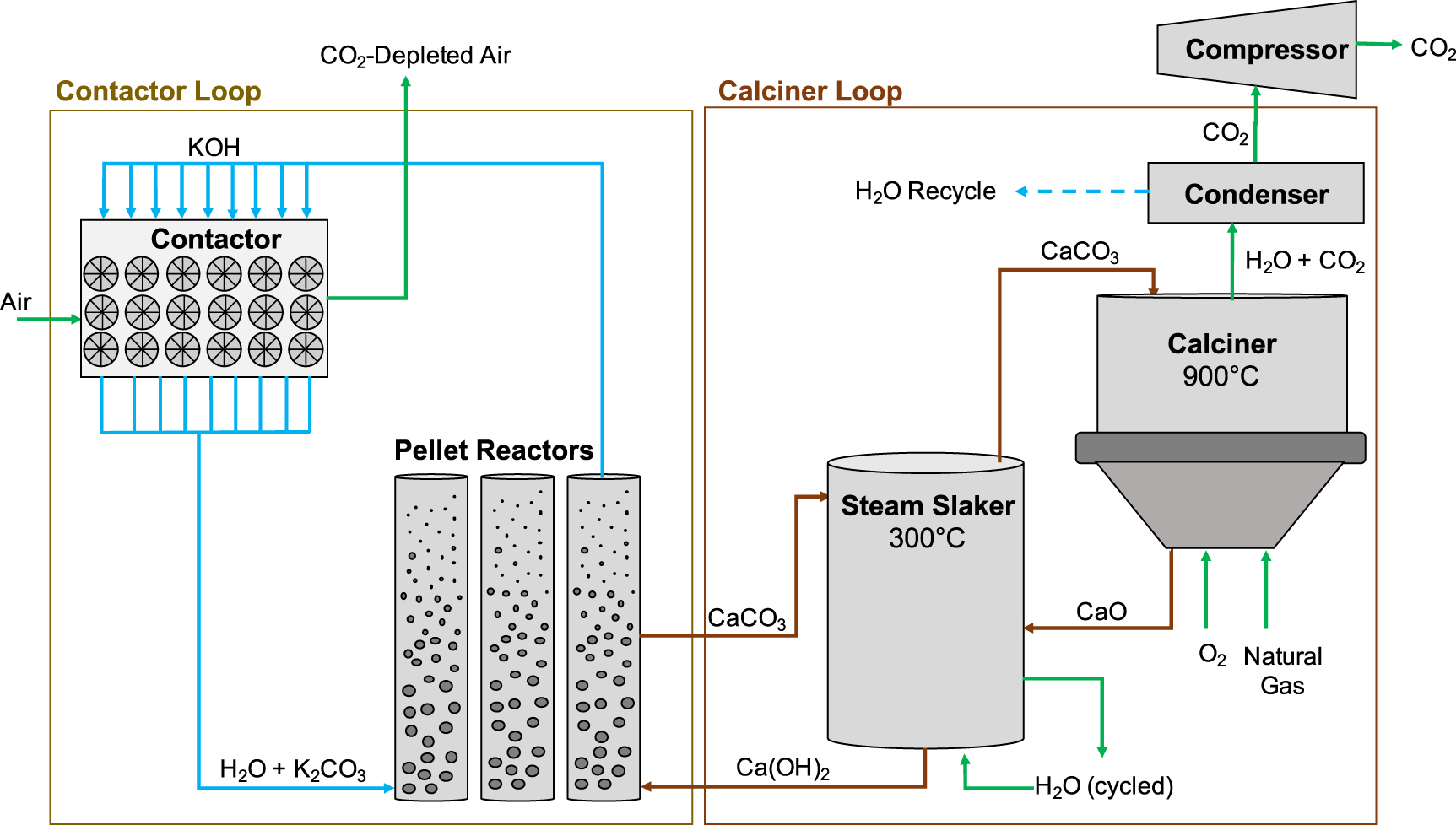
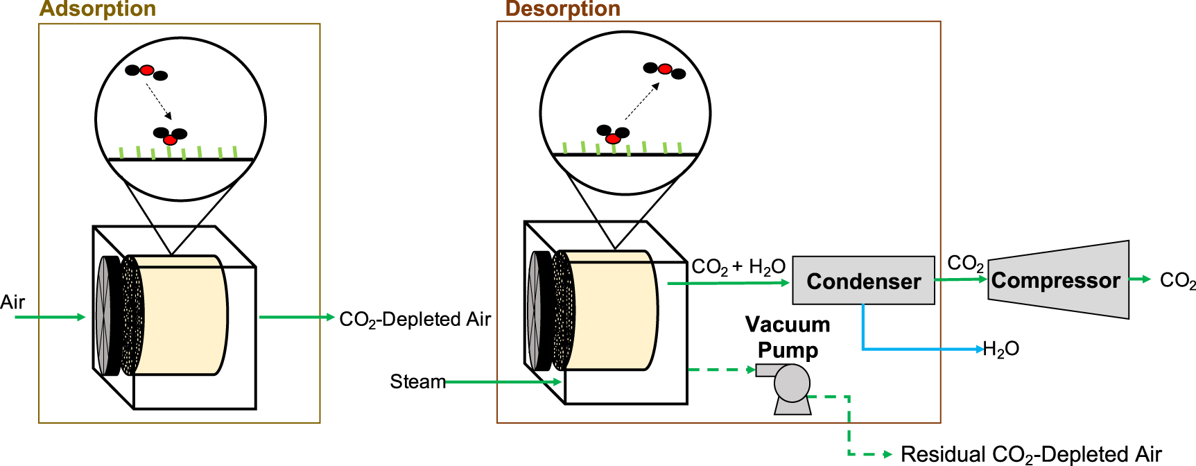
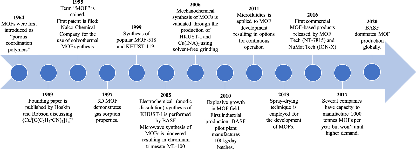