
Abstract
ABO3 perovskites host a huge range of symmetry lowering structural distortions, each of which can tune, or even switch on or off, different functional properties due to the strong coupling between the lattice, spin and charge degrees of freedom in these materials. The sheer number of different meta-stable structures present in perovskites creates a challenge for materials design via theory and simulation. Here, we tackle this issue using a first principles structure searching method on a prototypical half-metallic perovskite, La0.7Sr0.3MnO3, to predict how epitaxial strain can engineer structural and magnetic properties. We reveal a rich structural phase diagram through strain engineering in which the octahedral tilt pattern, and hence the crystal symmetry, is altered from the bulk. We show how the low-symmetry of the various phases in turn induces new structural modes, an increase in the magnetic anisotropy energy, and weak antiferromagnetic spin-canting.
Export citation and abstract BibTeX RIS

Original content from this work may be used under the terms of the Creative Commons Attribution 4.0 licence. Any further distribution of this work must maintain attribution to the author(s) and the title of the work, journal citation and DOI.
1. Introduction
It is well known that the interactions between electrons and the lattice are critical in understanding materials' properties such as ferroelectricity, superconductivity and charge ordering. In manganites (AMnO3, with A an alkaline earth metal, or lanthanide, or a mixture), a manganese oxide with perovskite-like crystal structure, Jahn–Teller (JT) distortions, a particular manifestation of the coupling between the electrons and the lattice, are needed to explain colossal magnetoresistance [1]. Indeed, the competition between JT, double-exchange mechanism, and the superexchange determines a rather complex phase diagram that includes charge ordering, antiferromagnetic (AFM) and ferromagnetic (FM) behaviour, insulating and half-metallic behaviour (metallic for one spin component, and semiconducting for the other), etc. Among the rich phase diagram [2] the so-called optimally doped composition (La0.7B0.3MnO3, with B=Ca, Sr, Ba) stands out for spintronic applications due to its FM half-metallic ground state with relatively high Curie temperature (TC ∼ 350 K for B=Sr). Bulk La0.7Sr0.3MnO3 (LSMO), the system of interest in this work, has rhombohedral crystal structure (space group  ), with lattice parameters ar
= 5.471 Å, and αr
= 60.43°, and Glazer's tilt pattern [3] described by three anti-phase rotations along the three pseudocubic axes (a−
a−
a−).
), with lattice parameters ar
= 5.471 Å, and αr
= 60.43°, and Glazer's tilt pattern [3] described by three anti-phase rotations along the three pseudocubic axes (a−
a−
a−).
Although the delicate equilibrium that comes from the competition of many subtle interactions can be a difficult challenge for understanding the properties of a particular sample, it also offers exciting opportunities for applications: by tuning the lattice we can control the electronic properties of the material. There are some ways to modify the structure of a perovskite by mechanical means. Application of hydrostatic pressure, or chemical pressure induced by dopants can vary the lattice parameters in bulk. For thin films, substrate-induced epitaxial strain has been extensively explored in the last few decades, and significant advances have been achieved in the optimization of the growth conditions to obtain LSMO thin films of superb quality, with atomically smooth surface morphology, homogeneous chemical composition, avoiding surface segregation and control on termination [4, 5]. Some of the most commonly used perovskite substrates for the growth of LSMO thin films are LaAlO3 (LAO), (LaAlO3)0.3(Sr2TaAlO6)0.7 (LSAT), NdGaO3 (NGO), SrTiO3 (STO), DyScO3, NdScO3 (NSO), or SmScO3 (SSO). While films grown onto LAO or NGO experience in-plane biaxial compressive strain, those on NSO or SSO would have biaxial tensile strains.
The strain fields forced on epitaxial thin films can not only affect the lattice constants, but also modify the tilt patterns in the perovskite, and consequently modify the electronic and magnetic properties of the samples (changes in the Mn–O–Mn bond angles affect the hopping of the eg states which have direct consequences on the double-exchange FM interaction) [4]. However, accurate determination of the lattice structure of these strained thin films is challenging, due to the difficulties in determining the oxygen positions. Indeed, contradictory results and predictions can be found in the literature. For LSMO thin films grown on STO (tensile strain) the out-of-phase rotations around the [001] axis is substantially suppressed, and according to Vailionis et al [6] both a+ a− c0 and a+ a+ c0 tilt patters are compatible with their XRD and EXAFS experiments. However, more recently Zhao et al [7] performed scanning transmission electron microscopy measurements that are only compatible with tilt system a− a− c0. Similarly, challenges exist within theory and simulation due to the complex energy landscape of perovskites containing a larger number of metastable phases. Often theoretical studies will restrict the number of structures considered to common tilt-patterns for computational tractability, but thereby risk neglecting the true ground state of the system. To have a better understanding of the physical properties of these thin films, it is critical to have realistic structural models of the crystal under different levels of strains.
In this work we use a first-principles random-structure searching method to predict the ground state symmetry of LSMO under different degrees of biaxial strain, both tensile and compressive, and analyse the possible changes in the magnetic properties. After describing the technicalities in section 2, we present an analysis of the obtained relaxed structures, in terms of symmetry groups and modified tilt patterns, and place it in the context of previous experimental evidence (section 3). Finally, we discuss the changes in the electronic levels and the magnetic anisotropy (section 4).
2. Methods
To perform a first-principles structure prediction of LSMO we employed a random structure searching method. LSMO, like most perovskites, can potentially exhibit a variety of distorted (meta)stable structures arising from Brillouin-zone (BZ) boundary instabilities. We therefore built a 40-atom cell from a 2 × 2 × 2 supercell of the five-atom formula unit, and moved each atom along the three spatial directions by a random amount between −0.1 and 0.1 Å. To simulate epitaxial strain, two in-plane lattice vectors were constrained to the pseudo-cubic value of one of five different substrates (100) LaAlO3 (LAO), (100) La0.3Sr0.7Al0.35Ta0.35O9 (LSAT), (001) NdGaO3 (NGO), (110) NdScO3 NSO and (110) SmScO3 (SSO), while the third lattice vector was allowed to relax in both magnitude and direction. These five different substrates were chosen as they provide a range of bi-axial strains, and since coherent epitaxial growth has been observed experimentally on each [4–6, 8–13]. For simplicity, pseudo-cubic structures for each of these substrates is assumed, which allows us to address the effect of homogeneous bi-axial strain on an equal footing; the effect of further uni-axial or shear components are beyond the scope here, as are interface/surface effects, but could be addressed in the future (see, for example, discussions in reference [14]).
The density-functional theory (DFT) calculations were performed using the spin-polarized Wu–Cohen (WC) exchange–correlation functional [15], as implemented in the Siesta code [16, 17]. Details of the pseudopotentials, numerical atomic orbitals, and La–Sr doping using the virtual crystal approximation are given in references [18, 19]. We find GGA-WC to reproduce bulk and surface properties of LSMO [20] that have been previously calculated using other functionals [18, 21]. Integrals in real space were performed on a mesh of a 1200 Ry cutoff [16], while BZ integrations were performed on a k mesh of a 30 Å cutoff [22]. 10 different random structures were built per substrate, and a colinear FM ordering was initially relaxed such that all atomic forces and stresses were below 0.01 eV Å−1 and 0.01 GPa respectively. A symmetry analysis, using FINDSYM [23], ISODISTORT [24] and INVARIANTS [25] from the ISOTROPY software suite, of the lowest energy structure for each epitaxial constraint was performed and reported below. Finally, non-colinear spin calculations were performed on each of the ground state structures using a recent spin–orbit implementation of the Siesta code [17, 26]. For each structure, the energy of all inequivalent spin-orientations were calculated to determine the easy axes.
3. Structural properties
Perovskites are known to display a strong coupling between octahedral tilting and strain [27–31]. The rich phase diagram of LSMO presented in figure 1, would appears to show that LSMO is no exception. Figure 1 shows the results of our first principles structure prediction for the effect of bi-axial (epitaxial) strain on the tilt pattern of LSMO. The ground state of LSMO without any applied strain has a rhombohedral crystal structure (space group  ), arising from anti-phase octahedral tilting around the three pseudo-cubic axes, corresponding to a Glazer's notation of a−
a−
a−. Forcing rhombohedral LSMO to bi-axially lattice match with a cubic crystal, will necessarily tune the out-of-plane lattice vector, and hence tilting around this vector, as compared to the in-plane components. This results in the a−
a−
c− tilt pattern (C2/c space group), which is indeed observed to be the ground state structure for the negligible strain applied by the LSAT substrate (figure 1). This also agrees with the calculations of references [11, 13, 32].
), arising from anti-phase octahedral tilting around the three pseudo-cubic axes, corresponding to a Glazer's notation of a−
a−
a−. Forcing rhombohedral LSMO to bi-axially lattice match with a cubic crystal, will necessarily tune the out-of-plane lattice vector, and hence tilting around this vector, as compared to the in-plane components. This results in the a−
a−
c− tilt pattern (C2/c space group), which is indeed observed to be the ground state structure for the negligible strain applied by the LSAT substrate (figure 1). This also agrees with the calculations of references [11, 13, 32].

Figure 1. Ground state LSMO (top) as a function of in-plane strain and substrate cell parameter (bottom). The in-plane strain is defined as ɛ = (a − a0)/a0 × 100%, where a0 is the pseudocubic (pc) lattice parameter of bulk LSMO (from DFT) and a is the pc lattice parameter of each substrate modelled. The labels row 1, row 2 and row 3 indicate the in-plane lattice parameter (Å), in-plane strain (ɛ) and substrate labels, respectively. The ground state space group and tilt pattern (Glazer's notation) for each strain state is shown at the top. La/Sr atoms are represented by green circles and Mn atoms are at the center of the MnO6 blue octahedra.
Download figure:
Standard image High-resolution imageOctahedral rotations can be approximately viewed as rigid unit modes whereby B–O bond lengths are kept fairly rigid [33]. In this picture the coupling to strain becomes implicit; constraining rigid B–O bond lengths while deviating B–O–B angles to less than 180° requires a reduction in the two lattice parameters in the plane of the oxygen motions. This is similar to the tension mechanism responsible for negative thermal expansion [34, 35]. Large in-plane bi-axial compressive strain therefore favours enhanced tilting around the c-axis in order to maintain equilibrium B–O bond lengths, in this rigid unit mode picture. Similarly, the resulting uniaxial out-of-plane tensile strain (from the Poisson effect), will reduce, and eventually destroy, tilting around the in-plane axes. This results in the a0
a0
c− (I4/mcm space group) tilting pattern under large bi-axial compressive strain applied by the LAO substrate, which the DFT calculations indeed find to be the ground state. If the tilting around both in-plane axes are not suppressed equally at intermediate values of compressive strains, one might expect a−
b−
c− followed by a0
b−
c− (and finally a0
a0
c−) phases to appear as the bi-axial compressive strain increases. The a−
b−
c− ( space group) is indeed seen at low values of compressive strain induced by the NGO substrate. We would likely expect to see the a0
b−
c− tilt pattern to appear for strains somewhere between LAO and NGO.
space group) is indeed seen at low values of compressive strain induced by the NGO substrate. We would likely expect to see the a0
b−
c− tilt pattern to appear for strains somewhere between LAO and NGO.
Experimentally, the large strain induced by LAO creates misfit dislocations to relieve the strain beyond a critical thickness of just 2–3 nm [36, 37], and thinner films may still undergo twinning or domain wall formation [38, 39]. Furthermore, ultrathin films will be affected by interface and surface effects not considered here and experimental verification of subtle structural changes by oxygen motions in three dimensions in ultrathin films is very challenging. The situation of NGO is different; while the strain is not so large to create misfit dislocations in thin films, a complication instead arises due to the tilt pattern for NGO itself influencing the LSMO interfacial tilting [11, 40, 41]. Ignoring this interfacial region, the tilt pattern in the bulk of thicker films (or with untilted buffer layers) has been proposed to be a+ a− a−, a+ b− c− [6], or a0 b+ c− [40] from x-ray reciprocal space maps and strain compatibility arguments, or a− a− c− from first principles calculations relaxing from the bulk structure [11]. Our calculations tend to agree with references [12, 41] that one of the in-plane rotations goes to nearly zero, but that the other two rotations are anti-phase, not in-phase (leading to a− b− c−, nearly a0 b− c−, rather than a0 b+ c−). Indeed, at no point in our structure searching method do we see evidence for in-phase rotations under any strain conditions. However, we have not considered the effect of interface octahedral coupling constraints, and other interface/surface effects that may change the picture.
On the other side of the strain phase diagram, large in-plane bi-axial tensile strain would be expected to suppress octahedral rotations around the c-axis. It is more difficult to predict the effect on the octahedral rotations around the in-plane axes within the rigid unit mode picture, since for bi-axial in-plane tensile strain, and hence uniaxial out-of-plane compressive strain, one set of Mn–Mn bond lengths increase (in-plane) while the other decrease (out-of-plane). If the net effect is to suppress the octahedral rotations around the in-plane axes then, depending on whether the out-of-plane or in-plane rotations are suppressed first, we might expect a sequence of either a− a− c− → a− a− c0 (→a− b− c0) → a− b0 c0 (→a0 a0 a0), or a sequence of a− a− c− (→a− b− c−) → a− b0 c− → a− b0 b0 (→a0 a0 a0). Our calculations suggest the large in-plane bi-axial tensile strain applied by SSO and NSO indeed give rise to a a− b0 b0 phase. It should be noted that whilst this tilt pattern is the same as that seen for the LAO substrate with I4/mcm space group, the tilt axis has rotated in-plane. The combination of bi-axial strain and tilting along these axes lowers the symmetry further to Fmmm. While coherent epitaxial growth of LSMO on SSO and NSO have been reported [8], there is little known experimentally of the LSMO octahedral tilting in these thin films to the best of the authors' knowledge.
For intermediate tensile strains somewhere between LSAT and SSO, we might expect to see the a− a− c0, a− b− c−, a− b0 c− and/or a− b− c0 tilt patterns to appear. The a− a− c0 tilt pattern has indeed been measured in some experiments with a SrTiO3 substrate [7]. We again note that our DFT results do not predict the appearance of in-phase octahedral tilting for any of the strain conditions considered, which would tend to disagree with the alternative tilt pattern a+ a− c0 or a+ a+ c0 reported with a SrTiO3 substrate [6]. However, we have not considered interface/surface effects that may change the picture.
In order to further understand the effect of the various tilt patterns on the symmetry breaking of LSMO, it is convenient to describe the structural degrees of freedom as transforming as irreducible representations (irreps) of the parent undistorted perovskite space group ( ) (and setting, for which we take the A-site at the origin in all irrep labels that follow). The various modes transforming as irreps present in each of the obtained ground state structures are listed in table 1, along with the magnitude of each irrep along each OPD. The anti-phase octahedral tilt transforms as the
  irrep, which appears in every structure, as expected. The magnitudes of the
  OPD components agrees with the Glazer notation described. For example, we can clearly see that the magnitudes of the three components to
  are not equal and non-zero in the case of NGO substrate, justifying the a−
b−
c− tilt pattern and
are not equal and non-zero in the case of NGO substrate, justifying the a−
b−
c− tilt pattern and  space group. Similarly, in the case of the LSAT substrate, we see that the magnitudes of the three components to
  are non-zero, but that two are equal, justifying the a−
a−
c− tilt pattern and C2/c space group. In addition to confirming our tilt pattern, the use of irreps allows us to observe whether there are additional distortion or strain modes present in any of these structures. While the
are non-zero, but that two are equal, justifying the a−
a−
c− tilt pattern and C2/c space group. In addition to confirming our tilt pattern, the use of irreps allows us to observe whether there are additional distortion or strain modes present in any of these structures. While the  bulk LSMO phase only allows for the
  distortion, the data in table 1 highlights that all epitaxially stabilised phases except I4/mcm allow for additional
  , and in some cases
  , distortions. These distortions consist of anti-polar Oxygen and A-cation motions at the R-point of the BZ, and are sketched in figure 2. (The low-symmetry
  structure also displays
  ,
,  ,
,  ,
,  and
and  modes that are not presented here for clarity). To understand the origin of these modes, we can expand the free energy as a Taylor expansion of modes transforming as these irreps, where each term must conserve crystal momentum, and time and spatial inversion symmetry. Such a process can be performed using the INVARIANTS tool [25], and provides, for example;

Table 1. Displacive and strain irrep amplitudes (Å) along each order parameter direction (OPD) for the ground state structures under epitaxial strain of LAO, NGO, LSAT, SSO and NSO substrates.
| Displacive mode amplitudes (Å) | |||||||||||
|---|---|---|---|---|---|---|---|---|---|---|---|
| System |

|

|

|

| |||||||
| a | b | c | a | b | c | a | b | c | a | b | |
| LAO (I4/mcm) | −0.560 45 | — | — |
|
|
|
|
|
|
|
|
NGO ( ) ) | 0.785 34 | −0.088 81 | −0.449 04 | 0.005 54 | 0.000 77 | 0.002 03 | −0.00 651 | −0.00035 | −0.003 99 | 0.000 09 | — |
| LSAT (C2/c) | 0.37876 | −0.257 92 | −0.378 76 | 0.001 09 | — | 0.001 09 | −0.000 16 | — | −0.000 16 | −0.000 70 | 0.000403 |
| SSO (Fmmm) | — | — | 0.543 35 | — | — | −0.032 20 | — | — | 0.029 03 |
|
|
| NSO (Fmmm) | — | 0.59588 | — | — | 0.046 98 | — | — | −0.04218 | — |
|
|
| Strain mode amplitudes (Å) | |||||
|---|---|---|---|---|---|

|

| ||||
| a | b | a | b | c | |
| LAO (I4/mcm) | 0.041 01 | — |
|
|
|
NGO ( ) ) | 0.007 42 | — | — | 0.006 46 | 0.001 39 |
| LSAT (C2/c) | −0.004 29 | −0.007 43 | 0.007 60 | — | −0.007 60 |
| SSO (Fmmm) | −0.035 90 | — |
|
|
|
| NSO (Fmmm) | −0.050 70 | — |
|
|
|
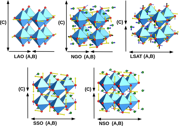
Figure 2. Schematic illustration of the irreps in the different LSMO distorted structures. The yellow, blue and black arrows placed at the octahedra represent the atomic displacement of the atoms owing to the  (O),
(O),  (O, La/Sr) and
  (O) modes respectively. The size for the blue and black arrows were exaggerated for visual purpose. The black arrows on the sides of each figure describes the elongation (double headed arrows) or contraction (two arrows pointing towards each other) of the cell parameters do to the mode
  (O). Note the
  mode is related to the angle between two cell parameters (α(b, c), β(a, c), γ(a, b)), but these are not indicated in the figures.
Download figure:
Standard image High-resolution imagewhere  are the lowest order anharmonic coupling terms in order parameters, Q, that transform as the
  and
and  irreps. These three terms include order parameters transforming as the
  and
and  modes that are linear in order. This means that the energy of the system is lowered by the appearance of these order parameters (with the correct sign), so long as the other terms are already superposed on the system. These modes are therefore said to be induced into the structure as secondary modes via 'improper' anharmonic couplings between them and the primary mode [42, 43]. From this equation it can be seen that the
  irrep, along certain order parameters directions, can induce the appearance of the
  irrep through a cubic-linear term (first line). In turn, these two modes can induce the appearance of the
  irrep through both a quadlinear term (second line) and bilinear-quadratic term (third line).
Similarly, the  shear strain mode appears in some of the tilted phases due to different anharmonic couplings between
  and the
  primary mode along different OPDs. The following is representative of such a trilinear term, for the case of the C2/c space group:

Since these secondary modes have an 'improper' appearance arising from higher-order anharmonic couplings, their magnitudes are much smaller than the primary distortions, as can be seen in table 1.
We note that ordering of the Q2 JT mode [44] at the M-point ( ), often observed in JT active perovskites [45], is not seen in any of our LSMO ground state structures. On the other hand, the R-point ordering of the Q2 or Q3 mode transforms as the
  irrep which is observed. However we reason above (see discussion around equation (1)) that its existence is structural rather than electronic in nature, and that the structural higher-order anharmonic couplings render its magnitude to be almost negligible. Finally, we note ordering of the Q3 mode at the Γ point transforms precisely as the bi-axial epitaxial strain,
  . Whilst this epitaxial strain is also not expected to arise from the JT effect, its magnitude is large and is expected to effect the electronic and magnetic properties, as we describe in the next section. While our calculations do not predict the appearance of any static ordering of distortions arising from the JT effect, their dynamic appearance may be possible [46], though this is beyond the scope of the current study.
4. Electronic and magnetic properties
Due to the crystal field on the MnO6 octahedra, the five 3d orbitals of Mn are split into a triplet t2g , and a doublet eg state, which is higher in energy and partially occupied. Distortion of the oxygen octahedral lattice due to biaxial strain can further split the degeneracy of these orbitals. In our analysis of the electronic levels via the partial density of states projected on Mn-3d orbitals (figure 3) we do not observe dramatic changes. As expected, compressive strain favors 3z2 − r2 over x2 − y2, and the opposite for tensile strain. The largest differences are observed for LAO and NSO, where the 3z2 − r2 level shifts by ∼0.25 eV to higher/lower energies, and the opposite for x2 − y2 (right panel in the figure shows an estimate of the shifts with respect to the unstrained LSMO levels). This trend appears to be predominantly due to strain, rather than tilting. The t2g state is also split due to the changes in symmetry. For tensile strain, the xy state is favored over xz/yz. Furthermore, the suppression of a tilt pattern seems to increase the localization of the state that is perpendicular to the axis that keeps the rotation (xy for LAO—highlighted in light blue in the figure–, or xz/yz for SSO/NSO). We note that the distortion of the MnO6 octahedra obtained for the larger strains (SSO and NSO substrates), and the different tilt pattern gives rise to three slightly different contributions of the xy, xz, and yz orbitals. Finally, we observe an increase of the half-metallic gap by tensile strain, induced by a shift of ∼0.25 eV in the minority spin t2g states, as shown in the far right panel in figure 3.
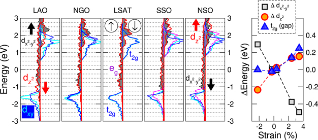
Figure 3. Projected density of states on the Mn-3d atomic orbitals, showing majority and minority spin components (left and right panels, as indicated by the thin arrows in circles in the center of the image) for each of the substrates studied. The metallic eg
state is split onto d
 (black shaded curve) and d
 (red line) states under strain, which shift upwards/downwards for compressive/tensile biaxial strain, respectively, as sketched by the thick black/red arrows. The t2g
state, is composed by dxy
(cyan), and dxz
, dyz
(blue/magenta), and can also be affected by the strain. Right panel: estimated shift in energy for d
(red line) states under strain, which shift upwards/downwards for compressive/tensile biaxial strain, respectively, as sketched by the thick black/red arrows. The t2g
state, is composed by dxy
(cyan), and dxz
, dyz
(blue/magenta), and can also be affected by the strain. Right panel: estimated shift in energy for d
 , d
, d
 , and t
 states under strain.
Download figure:
Standard image High-resolution imageDifferences in the occupation of the 3z2 − r2/x2 − y2 orbitals is typically linked to variations in the magnetic couplings in the system, and in particular affect the magnetic anisotropy, as we discuss next.
The various FM easy axes can be described by the magnitudes of each of the OPDs of the m
 FM irrep. The various inequivalent choices of OPDs were found using ISODISTORT [24] by superposing m
 onto each of the ground state structures. Fully relativistic non-colinear spin calculations, using a recent spin–orbit implementation of the Siestacode [17, 26], were then performed on each of the different magnetic orientations for each of the strain engineered ground state structures. The energies of each of these orderings, as well as the magnitude of each OPD of the corresponding relaxed magnetic irrep, are presented in table 2. A schematic of the ground state magnetic ordering for each strain state is presented in figure 4. At this point we emphasise that the magnetic anisotropy energy (MAE) in some systems is likely to be less than the accuracy of our DFT. While we cannot confidently state the easy axis in such cases, we can look more broadly at trends with strain.
Table 2. Magnetic irrep amplitudes (normalised units) along each OPD for the ground state structures under epitaxial strain of LAO, NGO, LSAT, SSO and NSO substrates. The number in square parentheses indicates the magnetic moment directions with respect to the pseudo-cubic orientation.
| Magnetic mode amplitudes | |||||||
|---|---|---|---|---|---|---|---|
| Magnetic space group |
m

|
m

| Relative energy (meV/f.u.) | ||||
| a | b | c | a | b | c | ||
| LAO | |||||||
| 69.524 [100] | — | — | −1.437 67 | — | — | 0.020 95 | 0.29 |
| 72.544 [110] | 1.437 75 | 1.437 75 | — | — | −0.019 84 | 0.019 84 | 0.29 |
| 15.89 [111] | −0.816 43 | −1.153 47 | 1.153 47 | 0.015 39 | — | 0.015 39 | 0.21 |
| 12.62 [011] | 0.990 81 | — | −0.991 27 | — | — | 0.003 15 | 0.16 |
| 140.547 [001] | — | — | 1.368 02 |
|
|
| 0.00 |
| NGO | |||||||
2.4 ![$\left[\bar{1}10\right]$](https://content.cld.iop.org/journals/2516-1075/3/2/024001/revision3/estabe6afieqn56.gif)
| 2.006 15 | 2.005 92 | −0.000 20 | 0.007 70 | −0.017 40 | 0.017 42 | 0.03 |
2.4 ![$\left[\bar{1}00\right]$](https://content.cld.iop.org/journals/2516-1075/3/2/024001/revision3/estabe6afieqn57.gif)
| 2.836 72 | −0.000 20 | −0.000 10 | 0.013 51 | 0.000 06 | 0.024 48 | 0.03 |
2.4 ![$\left[\bar{1}1\bar{1}\right]$](https://content.cld.iop.org/journals/2516-1075/3/2/024001/revision3/estabe6afieqn58.gif)
| 1.418 36 | 1.418 24 | 1.988 01 | 0.005 24 | −0.021 06 | 0.013 47 | 0.03 |
| 2.4 [010] | 0.000 20 | 2.836 86 | −0.000 20 | −0.002 56 | −0.022 89 | 0.000 27 | 0.02 |
2.4 ![$\left[00\bar{1}\right]$](https://content.cld.iop.org/journals/2516-1075/3/2/024001/revision3/estabe6afieqn59.gif)
| — | −0.000 20 | 2.811 42 | 0.000 06 | −0.013 53 | 0.002 58 | 0.00 |
| LSAT | |||||||
15.89 ![$\left[\bar{1}11\right]$](https://content.cld.iop.org/journals/2516-1075/3/2/024001/revision3/estabe6afieqn60.gif)
| 1.003 34 | −0.987 64 | 0.987 64 | 0.012 27 | — | 0.012 27 | 0.03 |
| 15.89 [001] | 1.419 19 | 0.015 12 | −0.015 12 | 0.01108 | — | 0.011 08 | 0.03 |
15.89 ![$\left[\bar{1}10\right]$](https://content.cld.iop.org/journals/2516-1075/3/2/024001/revision3/estabe6afieqn61.gif)
| −0.000 09 | −1.411 64 | 1.411 64 | 0.006 73 | — | 0.006 73 | 0.01 |
| 15.85 [110] | — | 1.411 62 | 1.411 62 | −0.004 96 | −0.001 95 | 0.004 96 | 0.00 |
| SSO | |||||||
| 69.524 [001] | — | — | 1.456 71 | — | 0.013 21 | — | 0.25 |
69.524 ![$\left[0\bar{1}0\right]$](https://content.cld.iop.org/journals/2516-1075/3/2/024001/revision3/estabe6afieqn62.gif)
| — | — | −1.393 59 |
|
|
| 0.02 |
| 69.524 [100] | — | — | 1.393 61 | — | — | −0.011 77 | 0.00 |
| NSO | |||||||
| 69.524 [001] | — | — | 1.474 74 | — | — | −0.011 55 | 0.34 |
69.524 ![$\left[0\bar{1}0\right]$](https://content.cld.iop.org/journals/2516-1075/3/2/024001/revision3/estabe6afieqn63.gif)
| — | — | −1.385 08 | — | — | −0.011 89 | 0.00 |
| 69.524 [100] | — | — | 1.385 05 |
|
|
| 0.00 |
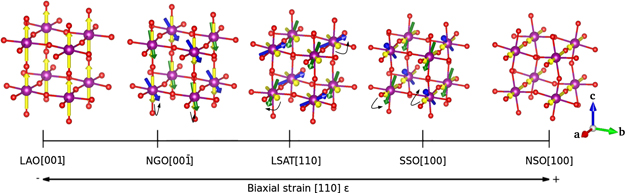
Figure 4. A schematic illustration of the ground state magnetic ordering of LSMO for each substrate. The yellow arrows represent the FM component, whereas the green and blue arrows represent the AFM component (i.e. canting, which has been exaggerated for visual purpose). The Mn and O atoms are represented by purple and red circles respectively.
Download figure:
Standard image High-resolution imageAs depicted in figure 4, the FM m
 orientation switches from out-of-plane to in-plane as LSMO undergoes compressive to tensile strain. LSMO under large compressive strain from LAO prefers an out-of-plane easy axis (along [001] pseudo-cubic direction) by about 0.3 meV/f.u. as compared to in-plane ([100] or [110] pseudo-cubic). This qualitatively agrees with experimental reports of an out-of-plane easy axis [4, 47–49]. Under the smaller compressive strain induced by NGO, our calculations show a very small MAE (only about 0.03 meV/f.u. energy difference between in-plane and out-of-plane), which is hard to resolve due to the high-level of accuracy required. Interestingly, there is an asymmetry in-plane [100] and [010] (pseudo-cubic) magnetic directions due to the asymmetry in octahedral tilting around these two axes, which was also noted in reference [12]. We emphasise that the fact that an in-plane easy axis has been reported experimentally [12, 50], while our calculations would suggest a very slight tendency towards out-of-plane should be considered with caution; the very low MAE in this case is being beyond the accuracy of our DFT. There is also an experimental report with [001] [12], highlighting how even small differences in growth and film thickness might possibly influence the ground state.
It is a similar scenario for the almost negligible strain induced by LSAT; we see a very small MAE, which is hard to resolve. The [110] (pseudo-cubic) easy axis does match experimental reports from reference [4, 51], however this might be fortuitous as again we do not expect our DFT to be able to resolve such energy differences. For larger tensile strains induced by SSO and NSO we see a larger MAE once again. LSMO now prefers an in-plane easy axis (along [100] pseudo-cubic direction) by 0.25 meV/f.u. (SSO) or 0.34 meV/f.u. (NSO) as compared to out-of-plane ([001]). While there does not appear to be much experimental data in this large tensile strain regime, smaller tensile strain from STO appears to show either [110] [4, 52] or [100] [4] easy axes.
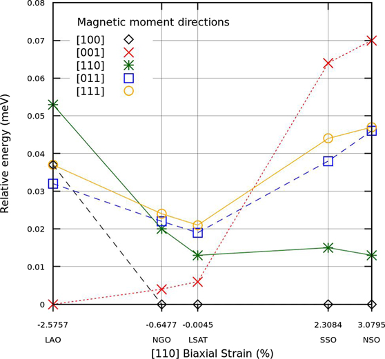
To decompose the effects of strain vs octahedral tilting on MAE, we have also computed the energy of various magnetic orientations in the five-atom undistorted, but strained, LSMO. Figure 5 shows that the easy axis when compressively strained in-plane is along [100], while it is along [001] for tensile strains. This trend would appear to agree with that expected from simple arguments based on 3z2 − r2 vs x2 − y2 orbital occupation [12, 48, 50, 51]; interactions between neighbouring Mn 3z2 − r2 (x2 − y2) orbitals, mediated by O2p, results in larger hopping and bandwidth and hence angular momentum and spin–orbit coupling along the out-of-plane (in-plane) direction. As described above, this orbital occupation is predominantly affected by strain, rather than tilting. The tilted structures therefore show similar 3z2 − r2 orbital occupation, and hence magnetic easy axes (compare figure 5 with figure 4). While trends in magnetic easy axes between tilted and untilted systems appear to be similar, we note that tilting does appear to substantially increase the MAE (cf 0.05–0.07 meV/f.u. for untilted LAO/NSO and 0.3–0.34 meV/f.u. for tilted LAO/NSO).
Figure 5. Energy per formula unit for each (pseudo-cubic) moment direction, relative to the ground state orientation, as a function of strain. The data plotted here is for undistorted, but strained, LSMO.
Download figure:
Standard image High-resolution image
Interestingly, some of the magnetic phases consist not only of the FM m
 irrep, but additionally contain small amounts of m
 (see table 2). This is a BZ boundary magnetic mode, and therefore amounts to a weak AFM canting superposed on the predominant FM. In a similar fashion as to the structural analysis above, we can now expand the free energy to also include terms dependent on order parameters transforming as magnetic irreps and find, for example;

This trilinear term underlines the origin of the m
 weak AFM canting. Since the term is linear in Q (m
 ), the free energy of the system is lowered by its appearance (with the correct sign), once octahedral tilting (
 ) and FM (m
 ) are non-zero along certain OPDs. Therefore the origin of the weak AFM canting apparent in some structures, is through an 'improper' appearance in a similar fashion to some of the structural modes above. The underlying mechanism can be similarly described via the Dzyaloshinsky–Moriya interaction [53, 54], which was indeed first originally rationalized based on such symmetry arguments alone [53].
Since weak-AFM canting manifests via higher order anharmonic terms, we therefore would also expect it to be small in magnitude, which is indeed confirmed in table 2. We note that Hubbard-like U and J terms, which were not considered in our calculations, can strongly affect canting angle magnitudes, but the symmetry alone controls its appearance.
5. Conclusion
We have used a first principles structure searching method to consider the phase diagram of epitaxial La0.7Sr0.3MnO3. As opposed to simulating a small finite set of known structures, these unbiased calculations have predicted new structural phases that can be induced via epitaxial strain engineering. The new phases consist of different octahedral tilt patterns which change the crystal symmetry. Through group theoretical analyses, we have shown how this symmetry breaking induces the appearance of secondary modes (zone-boundary A-site and oxygen anti-polar motions, and shear strain) via anharmonic coupling terms. We further considered the effect of spin–orbit coupling on the magnetic moments, and revealed the appearance of weak AFM canting. The appearance of such canting can also be described via anharmonic coupling terms between the primary FM and tilt modes. Finally, we find a switching of the magnetic easy axis from out-of-plane under compressive strain, to in-plane under tensile. While we argue that this change in easy axis is largely due to strain, the octahedral tilting does substantially increase the magnitude of the MAE. We hope the study inspires similar structure prediction efforts combining first principles and group theory, as well as experimental engagement.
Acknowledgments
The work has been partly performed under the Project HPC-EUROPA3 (INFRAIA-2016-1-730897), with the support of the EC Research Innovation Action under the H2020 Programme. This work was supported by Spanish MINECO (the Severo Ochoa Center of Excellence Program under Grant No. SEV-2017-0706), Spanish MICIU, AEI and EU FEDER (Grant No. PGC2018-096955-B-C43), Generalitat de Catalunya (Grant No. 2017SGR1506 and the CERCA Programme), and the European Union MaX Center of Excellence (EU-H2020 Grant No. 824143), J Pilo acknowledges the scholarship granted for a postdoctoral stay at ICN2 by CONACYT.
Data availability statement
All data that support the findings of this study are included within the article (and any supplementary files).