


Abstract
Cathodes are one of the key components of protonic ceramic fuel cells (PCFCs) requiring further development to enhance the performance of PCFCs. This encompasses the optimization of material compositions and microstructures, as well as a further understanding of the electrode processes. Here, a compositional optimization of a La0.5Ba0.5CoO3−δ—BaZrO3-based nano-composite cathode prepared by exsolution of a single-phase material was performed by substituting 5 and 10 mol% Y at the B-site in the BaZrO3 phase. Electrodes with different microstructures were prepared by two different deposition methods, spray coating and screen printing, and by varying the firing temperature from 600°C to 1100 °C. Further, composite electrodes were prepared by directly coating and firing the single-phase materials on the dense electrolyte to prepare symmetric cells. A good adhesion of the cathode to the electrolyte was observed in all cases. In general, a more homogeneous microstructure was observed for the cathodes prepared by screen printing. The single step method encompassing exsolution of the single phase and firing of the symmetric cells yielded significant improvement in the cathode performance compared to the other routes. The best electrochemical performance was observed for La0.5Ba0.5CoO3−δ—BaZr0.9Y0.1O2.95 cathode with an area specific resistance of 4.02 Ω · cm2 at 400 °C and 0.21 Ω · cm2 at 600 °C in 3% moist synthetic air. These results are among the best reported for cathodes of PCFCs as will be discussed.
Export citation and abstract BibTeX RIS

Original content from this work may be used under the terms of the Creative Commons Attribution 3.0 licence. Any further distribution of this work must maintain attribution to the author(s) and the title of the work, journal citation and DOI.
Introduction
Fuel cells are attractive energy systems providing excellent energy conversion efficiencies [1]. Among the different types of fuel cells, protonic ceramic fuel cells (PCFCs) have received increasing interest. Proton conducting electrolytes can operate in the temperature range 350 °C–700 °C due to the lower activation energy for proton conduction compared to oxygen ion conduction [2, 3]. As a result of the lower operation temperature many challenges can be overcome, such as high costs e.g. due to the need for expensive steels for high temperature fuel cells and material degradation and reactivity between the components [4, 5]. PCFCs also prolong the lifetime of the cells [1, 6]. Moreover, the formation of water at the cathode side prevents fuel dilution. Despite these advantages the lack of suitable cathode materials is one of the main challenges in the development of PCFCs [7–9]. The optimal microstructural parameters of a PCFC cathode have not yet been established. While detailed studies have been performed to elucidate the effects of microstructural parameters (porosity, thickness, grain size, etc) of cathode performance in oxygen ion conducting fuel cells (SOFCs), few studies have been conducted on PCFC cathodes. Lee et al [10] pointed out the importance of the porosity in PCFC cathodes and concluded that the water product formation at the cathode in PCFCs plays an important role. Closed porosity will lead to trapped vapor reducing the triple phase boundaries (TPB), and for long operation times, to the appearance of detrimental secondary phases.
Several groups have focused their attention on perovskite type Ln0.5Ba0.5CoO3−δ (Ln=La, Nd, Pr, Sm, Gd, Y) [11–13] materials due to their excellent oxygen ion and electronic conductivity [13–17]. With only mixed oxygen ion and electronic conduction in the cathode materials, the reaction sites are restricted to the electrolyte/cathode interface. Therefore, the introduction of proton conductivity in the cathode is necessary in order to activate the whole cathode [18]. Ceramic-ceramic composite cathodes consisting of the La0.5Ba0.5CoO3−δ oxygen ion and electronic conductor and the BaZrO3-based protonic conductor would therefore potentially increase the performance of the fuel cell. Moreover, by choosing the same proton conducting material for the cathode and the electrolyte, the adhesion of the electrode to the electrolyte will be improved and potential thermo-mechanical mismatch between the electrolyte and the electrode will be reduced.
We have recently developed a novel route to synthesize La0.5Ba0.5CoO3−δ—BaZrO3 composite cathode materials [19]. The method is based on in situ driven decomposition of a single phase material by exsolution and the possibility to induce phase decomposition by red-ox chemistry has been demonstrated [19]. The flexibility and adaptability of the exsolution method was demonstrated by the addition of Mn, Fe and Y giving a total of 7 cations in La0.5Ba0.5Co1/3Mn1/3Fe1/3O3−δ—BaZr1−zYzO3−δ [20]. Exsolution of nanoparticles such as nickel, ruthenium or other catalyst metals in SOFC and PCFC anodes under reducing conditions has been investigated [21–24]. On the contrary, cathodes operate at oxidizing conditions, and therefore, synthesis based on oxidation-driven exsolution from a single-phase material will produce suitable cathode materials at the operation conditions. Homogeneous composite cathodes with tailored chemical compositions can be prepared by the exsolution-based synthesis approach [19, 20], but further in-depth studies of the effect of microstructure and morphology of the cathodes are necessary.
Here, we report on the effects of different deposition methods such as screen printing and spray coating, variable firing temperatures and exsolution approaches in order to further optimize the processing conditions of the composite PCFC cathodes. The chemical composition of the composite electrodes was varied by doping the BaZrO3 phase with Y with the following nominal compositions: La0.5Ba0.5CoO3−δ—BaZr1−zYzO3−δ composites with z = 0, 0.05 and 0.1. Thorough characterization and analysis of the powder materials and the cathodes as a function of the various processing parameters are presented. The electrochemical performance of these new composites is presented and significant improvement in performance and the potential of these compositions as cathodes for PCFC with BaZrO3-based electrolytes are demonstrated.
Method
Synthesis and sample preparation
Nanocomposite electrodes of nominal composition 0.6 La0.5Ba0.5CoO3−δ—0.4 BaZr1−zYzO3−δ (z = 0, 0.05 and 0.1) were prepared by a modified Pechini method followed by in situ oxidation-driven decomposition of a single phase material yielding exsolution [19]. The starting materials were bought from Sigma-Aldrich (Steinheim, Germany). The cation precursors for synthesis of the composites were barium nitrate (Ba(NO3)2, >99.999%), lanthanum nitrate hexahydrate (La(NO3)3 · 6H2O, >99.99%), zirconyl nitrate hydrate (ZrO(NO3)2 · xH2O, >99%), cobalt nitrate hydrate (Co(NO3)2 · 6H2O, >99.999%) and yttrium nitrate tetrahydrate (Y(NO3)3 · 4H2O, >99.8%). Ethylenediaminetetraacetic acid (EDTA, >99%) as well as citric acid (CA, >99%) were used as complexing agents. The synthesis of the materials was done as described in previous works [19, 20]. Stoichiometric amounts of cations were mixed to give nominal compositions La0.3Ba0.7Zr0.4-wYwCo0.6O3−δ (w = 0, 0.02 and 0.04). The precursor powders were pressed into pellets and annealed in N2 atmosphere at 715 °C for 8 h in order to achieve single phase materials: La0.3Ba0.7Zr0.4Co0.6O3−δ (marked as Co0Y), La0.3Ba0.7Zr0.38Y0.02Co0.6O3−δ (marked as Co5Y) and La0.3Ba0.7Zr0.36Y0.04Co0.6O3−δ (marked as Co10Y). The pellets were crushed, and the resulting powders were further pressed into pellets at 50 MPa and calcined in ambient air at 900 °C for 2 h in order to exsolve Co0Y into the nominal composition 0.6 La0.5Ba0.5CoO3−δ—0.4 BaZrO3 composite (Co0Yex). Co5Y and Co10Y composites were exsolved at 1100 °C for 2 h (Co5Yex and Co10Yex). Table 1 resumes the nominal composition and nomenclature of the composite compositions. All the thermal treatments were performed using 2 °C min−1 cooling and heating rates.
Table 1. Nominal composition and nomenclature of Co0Yex, Co5Yex and Co10Yex nanocomposite cathodes. Refined compositions and molar ratios of the composite phases were obtained from Rietveld refinements of XRD patterns.
| Nominal composition | Refined composition (Rietveld) | Refined composite ratio (mol%) | ||||
|---|---|---|---|---|---|---|
| Code | LB phase | BZ phase | La1−xBaxCoO3−δ phase | BaZr1−z−yYzCoyO3−δ phase | LB phase | BZ phase |
| Co0Y [19] | La0.5Ba0.5CoO3−δ | BaZrO3 | La0.8Ba0.2CoO3−δ | BaZr0.6Co0.4O3−δ | 40 | 60 |
| Co5Y | La0.5Ba0.5CoO3−δ | BaZr0.95Y0.05O3−δ | La0.68Ba0.32CoO3−δ | BaZr0.69Y0.04Co0.27O3−δ | 40 | 60 |
| Co10Y | La0.5Ba0.5CoO3−δ | BaZr0.9Y0.1O3−δ | La0.62Ba0.38CoO3−δ | BaZr0.68Y0.07Co0.25O3−δ | 38 | 62 |
BaZr0.9Y0.1O2.95 (BZY10) electrolyte supported symmetric cells with cathode materials were prepared as follows. BZY10 electrolyte powder was prepared by spray-pyrolysis (CerPoTech AS, Tiller, Norway. Purity >99%) of a mixture of nitrate solutions containing stoichiometric amounts of the cations. Dense samples were prepared by solid state sintering as described by Sazinas et al [25]. Green cylindrical pellets (12 mmø) were formed by uniaxial pressing at 100 MPa with subsequent cold isostatic pressing (CIP) at 200 MPa. The sintering of the pellets was performed using sacrificial powder (BaZr0.8Y0.2O2.9 with 10 wt% BaCO3) at 1600 °C for 10 h in ambient air with 10 °C min−1 heating rate. The surface of the sintered electrolyte pellets was ground with SiC paper.
Two deposition methods were used to study the cathode materials, spray coating and screen printing. For the cathodes prepared by the ex situ method, the composite materials were crushed and ground into a fine powder prior the dispersion or ink production. Co0Yex powder was dispersed in ethanol using 5 wt% solid content and 3 wt% Dolacol D 1003 (Zschimmer & Schwarz, GmbH) as a dispersant. The dispersion was deposited by spray coating on both sides of the BZY10 electrolyte pellets. The symmetric cells were fired at 900 °C for 4 h in ambient air. The inks for screen printing were prepared by mixing Co0Yex, Co5Yex or Co10Yex cathode powders (3 g) with dispersant (1 g, 20 wt%, Solsperse Lubrizol 28 000 in terpineol) and binder (0.2 g, 5 wt% Heraeus V-006 in terpineol) in a mortar [8]. The inks were screen-printed on both sides of the electrolyte pellets. Co0Yex symmetric cells were fired for 2 h at 600 °C, 700 °C, 800 °C and 900 °C while Co5Yex and Co10Yex were fired at 600 °C and 1100 °C for 2 h (with 2 h dwell at 600 °C to assure the complete decomposition of the organics at this temperature).
In situ exsolution of Co0Y and Co10Y materials was also studied by preparing inks of the single-phase materials. The single-phase materials were crushed and ground into a fine powder prior to screen printing ink preparation. The inks were prepared and printed in the same manner as for the screen-printed ex situ composite cathodes. The in situ exsolved symmetric cells were fired for 2 h at 900 °C (Co0Yin) or 1100 °C (Co10Yin) with 2 h dwell at 600 °C, in order to exsolve the single phases into the composite cathode materials. The different sample compositions, deposition methods and thermal treatments are summarized in table 2.
Table 2. Summary of processing parameters for symmetrical cells with Co0Y, Co5Y and Co10Y cathode materials.
| Spray coating ex situ | Screen printing ex situ | Screen printing in situ | ||||||
|---|---|---|---|---|---|---|---|---|
| Code | 900 °C | 600 °C | 700 °C | 800 °C | 900 °C | 1100 °C | 900 °C | 1100 °C |
| Co0Y | X | x | x | x | x | x | ||
| Co5Y | x | x | ||||||
| Co10Y | x | x | x | |||||
Characterization
The prepared powder materials and the cathodes in symmetric cell configuration were analyzed by x-ray diffraction (XRD) before and after electrochemical impedance spectroscopy (EIS) using a Bruker D8 DaVinci equipped with LynxeyeTM detector and CuKα radiation. Lattice parameters of the single phases annealed in N2 were obtained by Profile fitting of a Pm  m cubic perovskite structure. Unit cell parameters of the composites were refined by the Rietveld method using Bruker AXS TOPAS software v5. The exsolved composites were refined using two cubic perovskite phases with Pm
  m space group, La1−xBaxCoO3−δ and BaZr1−z−yYzCoyO3−δ. The structural data of the nominal compositions were used as the starting point for Rietveld refinement. Lattice parameters and x, y and z occupancy were refined.
The microstructure and adhesion of the composite cathodes were studied by field emission scanning electron microscopy (SEM, Zeiss Gemini ultra 55). The cross section of the fracture surface of symmetric cells before and after electrochemical testing was examined. The adhesion of the cathodes to the electrolyte was evaluated by visual investigation and verified by SEM. In addition, the 'carbon tape' test was conducted. The conductive carbon tape used to mount the unpolished cross section samples for SEM analysis was used in an attempt to peel off the cathode layers. If the carbon tape was removed without delamination of the cathode and no residues of the cathode are left on the carbon tape, the carbon tape test was passed. The porosity of the cathodes was studied on polished cross section symmetric cells embedded in epoxy with an energy-selected backscatter (EsB) detector with filtering grid attached to the microscope. The surface of the samples was polished with SiC papers and diamond suspensions down to 1 μm. The porosity of the cathodes was estimated from micrographs at different magnifications by counting the volume fraction of the voids using the GIMP software [26]. The porosity of a minimum of 40 images was averaged for each sample.
EIS of symmetrical cells was carried out in moist (pH2O = 0.03 atm) synthetic air from 400 to 600 °C, in temperature intervals of 50 °C (with a cooling rate of 1 °C min−1 and 8 h dwell before each measurement) using a ProboStatTM (NorECs AS, Norway) set-up and an Alpha A (Novocontrol Technologies) impedance analyzer. The signal amplitude was 50 mV under open circuit voltage (OCV) in the 10−2–106 Hz frequency range. Platinum paste (Pt ink-C2000904P3, Gwent) was applied onto the spray coated cathodes as a current collector and gold paste (AU-I, Fuel cell materials) was used for the screen-printed symmetric cells. Platinum was employed as a conducting wire for all the samples. Synthetic air was flushed through a bubbler containing distilled water at 25 °C in order to achieve 3% moist atmosphere. The modelling of the experimental data was fitted using ZView software v 3.5 (Scribner). The equivalent circuit LRs(R1Q1)(R2Q2)(R3Q3) was used to fit all the experimental data. Ri and Qi are, respectively, the polarization resistance and the constant phase elements of each process. The ohmic resistance of the bulk electrolyte is represented by Rs and the inductance by L. The different processes were attributed to the electrolyte or electrode using the pseudo capacitances (C) [27].
Results
Single phase Co0Y, Co5Y and Co10Y materials with a cubic structure (Pm  m) were prepared at 715 °C by the modified Pechini route. The synthesis was optimized for the BaZrO3-based phase to accommodate Y doping up to 10 mol% on the B-site based on our previous work on Co0Y composition [19] and 3 M family compositions [20]. Different exsolution temperatures were required to achieve two-phase composites: 900 °C for Co0Y and 1100 °C for the 5% and 10% Y containing compositions.
Rietveld refinements of the diffractograms of the ex situ exsolved Co5Yex and Co10Yex cathodes are shown in figure 1. The composition, diffraction patterns and the Rietveld refinement of Co0Yex are described in our previous work [19]. The chemical composition obtained by Rietveld refinement, and the molar composite ratio of Co0Yex, Co5Yex and Co10Yex cathode materials are included in table 1. These composite materials consisted of two cubic Pm  m perovskite phases La1−xBaxCoO3−δ (LB) and BaZr1−z−yYzCoyO3−δ (BZ), also indicating a significant Co-content in the BZ phase. No diffraction lines due to other phases were visible in the range from 5 to 75 °(only data in the range 20 to 60° shown).

Figure 1. Rietveld refinement of selected 2ϴ range for XRD patterns of composites (a) Co5Yex and (b) Co10Yex using the cubic Pm  m space group for the two phases present in the diffractograms.
Download figure:
Standard image High-resolution imageThe cathodes made by in situ exsolution were analyzed by XRD in the symmetric cell configuration and compared to the ex situ cathodes (figure 2(a)). No variation in the 2ϴ-position of the reflection was observed and only minor changes in diffraction line widths were observed. It can be inferred from the diffractograms that the in situ cathodes were exsolved to the same composition as the ex situ cathodes.

Figure 2. (a) XRD patterns of the composite cathodes with nominal composition 0.6 La0.5Ba0.5CoO3−δ—0.4 BaZr1−zYzO3−δ. The reflections of the BZY10 electrolyte from the symmetric cell can be seen in the in situ exsolved symmetric cell diffractograms. (b) Cubic unit cell parameters of the precursor annealed phase (open) and the composite phases (blue and red) obtained by Rietveld refinements. Lines are guides for the eye. Cell parameter for Y-doped BaZrO3 is included for comparison (black) [25]. BZ: BaZr0.7Y0.1Co0.2O3−δ based phase. LB: La0.75Ba0.25CoO3−δ based phase.
Download figure:
Standard image High-resolution imageThe unit cell parameters of the precursor single phases annealed in N2 and the LB and BZ phases of the ex situ composites are presented in figure 2(b). The unit cell of the single-phase material and the BZ phase showed a slight increase with increasing Y content. The Y-doped BaZrO3, shown for comparison [25], has a larger cell parameter than the exsolved BZ phase but reveals a comparative compositional dependence as shown in figure 2(b). The smaller unit cell with respect to pure Y-doped BaZrO3 is a consequence of the significant amount of Co in the BZ phase. The LB phase had a constant cell parameter of 3.870(1) Å for all the compositions. This value is smaller than for pure La0.5Ba0.5CoO3−δ (3.893 Å [17]) due to a larger content of La.
The cross section micrographs of the Co0Yex cathodes deposited by spray coating and screen printing are compared in figure 3. Both deposition methods gave robust cathodes with a thickness above 20 μm. Cathodes with constant thickness were obtained by screen printing unlike spray coating as shown in figure 3(a).
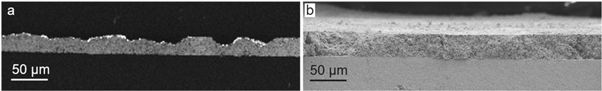
Figure 3. SEM images of Co0Yex cathode composites deposited by (a) spray coating and (b) screen printing and fired at 900 °C. The cathodes were ex situ exsolved.
Download figure:
Standard image High-resolution imageHighly porous cathodes (47% porosity (ε)) were prepared by spray coating after firing at 900 °C, as shown in figure 4(a). Higher magnification of the spray coated Co0Yex cathode (figure 4(b)) demonstrates the presence of a large amount of voids above 1 μm in size as well as smaller pores in the range 100–200 nm. The screen-printed cathodes had significantly lower porosity than the spray coated ones for all the firing temperatures (figures 4(c) to (f)). The Co0Yex cathode fired at 900 °C had 25% porosity, while the cathode fired at 600 °C had a porosity of 31%. Co5Yex screen-printed cathodes fired at 600 °C for 2 h (not shown) presented 40% porosity. Around 30% of the cathodes prepared by spray coating delaminated while performing the 'carbon tape' test. No delamination was observed for any of the screen-printed symmetric cells by the carbon tape test.

Figure 4. Backscattered SEM images of Co0Yex cathodes prepared by spray coating (a) and (b) and screen printing (c) to (f). The cathode composites were ex situ exsolved. The symmetric cells were fired at 900 °C (a) and (f) and at 600, 700 and 800 °C for (c)–(e), respectively. The images were taken at high contrast to distinguish the oxides and the porosity. The firing temperature and the porosity (ε) are included in the images. Traces of platinum current collector can be seen on the surface of the spray coated cathode (a).
Download figure:
Standard image High-resolution imageThe in situ prepared cathodes were fired and exsolved in a single step, which decreases the number of steps for the cathode layer production and simplifies the whole process. Figure 5 shows the good adhesion of all the cathodes and compares the microstructure of the cathodes formed by in situ and ex situ exsolution. The cathodes prepared via the in situ process presented an interconnected network (web-like) microstructure with large pore channels and high tortuosity. On the other hand, as the cathodes prepared by ex situ method were ground prior the ink production, the specific microstructure developed during exsolution is lost during this step. The microstructure of the ex situ cathodes also showed high porosity and good contiguity but with larger grains and no pore channels. The high magnification images of the in situ prepared cathodes showed highly porous web-like microstructure (figures 5(a) and (c)).

Figure 5. SEM images at low (a) to (d) and high magnification ((a1) to (d1)) of Co0Yex, Co0Yin, Co10Yex and Co10Yin cathode composites deposited by screen printing. Left column for the in situ exsolved cathodes and the right column for the ex situ exsolved cathodes. The ex situ exsolved symmetric cells (b) and (d) were fired at 600 °C.
Download figure:
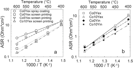
Standard image High-resolution imageImpedance spectroscopy of the symmetrical cells was performed and two resistances were assigned to the electrode on the basis of their capacitances, R2 with C2 ∼ 10−4 F cm−2 and R3 with C3 ∼ 10−2 F cm−2, while R1 was assigned to the electrolyte grain boundary response (C1 ∼ 9 · 10−10 F cm−2). The cathode ASR are calculated from the sum of R2 and R3 multiplied by the active area and divided by 2. The ASR in 3% moist synthetic air of the best performing ex situ exsolved cathodes are shown in figure 6(a), whereas all the experimental data for both ex situ and in situ exsolved electrodes is summarized in table 3. The symmetric cells prepared by screen printing show better performance than the cathodes deposited by spray coating. The spray coated Co0Yex electrode presented the lowest activation energy (Ea) of 0.60 eV (table 3) with an ASR of 18 Ω · cm2 at 400 °C and 1.54 Ω · cm2 at 600 °C. Better performance was observed for the Co10Yex composition (ASR = 10 Ω · cm2 at 400 °C and 0.18 Ω · cm2 at 600 °C) prepared by screen printing, although the activation energies were higher than for the spray coated cathodes (from 0.73 to 1.02 eV). The ASR of the in situ exsolved cathodes is presented in figure 6(b) and table 3. Both Co0Yin and Co10Yin cathodes showed an improved performance compared to their ex situ counterparts. The performance of the cells at low temperatures was further improved by 2–3 times for Co0Yin and Co10Yin cathodes with respect to Co0Yex and Co10Yex, respectively, while the electrodes perform similarly at 550 and 600 °C. Co10Yin showed the lowest ASR at 400 °C (=4.02 Ω · cm2) while at 600 °C the performance is similar to the ex situ cathodes (=0.21 Ω · cm2). The activation energies of the in situ exsolved cathodes (0.78 eV for Co0Yin and 0.73 eV for Co10Yin) were lower than the ex situ exsolved cathodes (0.92 eV for Co0Yex and 0.94 eV for Co10Yex). No visible changes of the symmetrical cells were observed by XRD nor SEM after the electrochemical testing compared to before testing.
Figure 6. Area specific resistance (ASR) of composite cathodes in symmetric cell configuration in 3% moist synthetic air in an Arrhenius diagram as a function of temperature: (a) Co0Yex, Co5Yex and Co10Yex (ex situ exsolved) and (b) Co0Y and Co10Y by in situ and ex situ exsolution.
Download figure:
Standard image High-resolution image
Table 3. Summary of the cathode area specific resistance (ASR (Ohm · cm2)) of the Co0Y, Co5Y and Co10Y composite cathodes from 400 to 600 °C at pH2O = 0.03 atm.
| ASR (Ohm · cm2) | ||||||||
|---|---|---|---|---|---|---|---|---|
| Screen printing | ||||||||
| Spray coating | Ex situ exsolution | In situ exsolution | ||||||
| T (°C) | Co0Yexb | Co0Yexa | Co5Yexa | Co10Yexa | Co0Yexb | Co10Yexc | Co0Yinb | Co10Yinc |
| 600 | 1.54 | 0.34 | 0.61 | 0.18 | 0.21 | 0.26 | 0.30 | 0.21 |
| 550 | 2.74 | 0.46 | 1.70 | 0.38 | 0.36 | 0.53 | 0.50 | 0.39 |
| 500 | 4.52 | 1.09 | 3.50 | 0.89 | 0.93 | 1.04 | 1.03 | 0.66 |
| 450 | 7.63 | 3.32 | 6.97 | 2.64 | 3.02 | 2.90 | 2.14 | 1.34 |
| 400 | 18.11 | 11.21 | 15.57 | 10.42 | 11.75 | 12.18 | 6.76 | 4.02 |
| Ea (eV) | 0.60 | 0.92 | 0.79 | 1.02 | 0.95 | 0.94 | 0.78 | 0.73 |
a600 °C firing temperature. b900 °C firing temperature. c1100 °C firing temperature.
Discussion
The synthesis of Co5Y and Co10Y materials by exsolution driven decomposition of a single-phase material was chosen due to the demonstrated robustness, flexibility and adaptability of the method [19, 20]. The reaction given in equation 1 is based on the hypothesis that the LB and BZ perovskite phases are not miscible at oxidizing conditions [19].

(1) After developing the synthesis method and characterizing the nanocomposite cathodes, it was proven that there is a significant solid solubility of cobalt in the BZ phase. In addition, it was further demonstrated that Y remains in the BZ phase of the composite as previously reported [20]. The crystal structure characterization of Co5Yex and Co10Yex nanocomposite cathodes, shown in figure 1 and table 1, are in good agreement with our previous work [19, 20]. Two-phase composites were successfully prepared and no secondary phases nor impurities could be detected by XRD.
The effect of four different processing steps on the cathode ASR was investigated: (1) the deposition method, (2) Y content, (3) firing temperature of the symmetric cells and (4) in situ and ex situ exsolution method. There are significant differences in the microstructure of the electrodes prepared by spray coating and screen printing as a more constant thickness was obtained for the screen-printed cathodes and a higher porosity and larger pore size were observed for the spray coated cathodes. These differences may primarily stem from the feedstock used for each method. Spray coating of ceramic-based slurries require the preparation of a slurry with a much lower ceramic loading compared to ceramic-based inks used for screen printing. The deposited spray coated layers have a lower green density, which will contribute to higher porosity and larger pore size after firing. In addition to this, the ink preparation for screen printing requires grinding of the paste which breaks down the remaining aggregates and gives more homogeneous cathode layers.
The advantages of the spray coating method are the simple preparation of the dispersions, the low amount of organic dispersant and the possibility to cover the whole electrolyte area avoiding the issue of making asymmetric cathodes. However, spray coating gives very porous cathodes with large voids due to the presence of aggregates, as shown in figures 4(a) and (b). Screen printing shows high reproducibility and for this application, it is faster than spray coating. The lowest ASR obtained in this work was for the electrodes presenting the lowest porosity and smaller pore size, prepared by the screen printing method. All the firing temperatures of the screen-printed cathodes shown in figure 4 gave good adhesion as they passed the 'carbon tape' test, even at a firing temperature as low as 600 °C. Therefore, only selected temperatures (600 °C and 1100 °C) were studied on Co5Yex and Co10Yex. These results demonstrate the possibility to obtain robust cathodes with good adhesion to the electrolyte at 600 °C, which is a much lower temperature than usually reported in the literature [8, 11, 28]. The good adhesion obtained for all the cathodes can be due to the compositional match between the BZ phase of the composite and the electrolyte as well as the small grain sizes in the composite cathodes. The adhesion failure in some spray coated cathodes can be due to a weaker electrolyte-cathode interface due to the larger porosity, which decreases the number of contact points. No reaction layer was observed between the electrode and the electrolyte by SEM nor were additional reflections visible by XRD. The effect of the Y doping was only further investigated for the screen-printed cathodes as this deposition method gave homogeneous thickness and well-adhered cathodes.
Likewise, Y doping in the BZ phase of the cathode resulted in an improvement of the electrochemical performance for the Co10Yex composition compared to Co5Yex and Co0Yex. Co5Yex cathodes showed no improvement relative to the screen-printed Co0Yex cathode. The Y doping is expected to be beneficial because of the higher proton conductivity observed with increasing Y doping in BZ [29]. At the same time, Co doping on the B-site introduces oxygen vacancies and increases the electronic conductivity [19]. Only the Co10Yex composition showed better performance than the Co0Yex. It is well known that microstructural changes have a larger effect on the electrochemical performance than small compositional variations [30]. Co5Yex possesses very similar ASR compared to Co0Yex but no improvement was observed due to a slightly higher porosity of 40%. The ASR of the Y containing cathodes in figure 6(a) shows significant enhancement of the performance for Co10Yex composition and further optimization was done on this composition. By in situ exsolving the composite cathodes on the symmetrical cells, the electrochemical performance was successfully improved in the low temperature range (400 °C–500 °C). The in situ exsolution evolved a web-like microstructure with large channels to promote gas diffusion along the cathode and increased triple phase boundaries (figures 5(a1) and (c1)). This microstructure is driven by the exsolution method due to the larger unit cell volume of the single phase than the composite, giving an additional porosity. The ex situ exsolved cathodes were ground in order to obtain a fine powder prior to the ink production which implies a certain breakdown of this morphology. The better performance of the in situ prepared cathodes is explained by the microstructure achieved by the exsolution mechanism. In addition, the reduction of the number of thermal steps is beneficial in terms of the cost and complexity of the process. The best reported performance at 400 °C in 3% moist synthetic air was obtained for the Co10Yin cathode, with ASR of 4.02 Ω · cm2. The performance of Co0Yin and Co10Yin cathodes at 600 °C is as low as 0.30 and 0.21 Ω · cm2, similar to the reported values for Co0Yex and Co10Yex in table 3. The lower resistance of the in situ prepared cathodes at lower temperatures leads to the lowering of the activation energies to below 0.78 eV. Experiments at different pO2 and pH2O would help to investigate the performance-limiting process or processes. Co10Yin cathode performance is in the same order of magnitude as the best materials reported in the literature, such as BaCo0.4Fe0.4Zr0.1Y0.1O3−δ (∼10 and 0.4 Ohm · cm2) by Duan et al [8] and BaGd0.8La0.2Co2O6−δ (∼6 and 0.2 Ohm · cm2) by Strandbakke et al [11] at 400 and 600 °C, respectively, at the same experimental conditions.
Conclusions
New 0.4 La0.68Ba0.32CoO3−δ—0.6 BaZr0.69Y0.04Co0.27O3−δ (Co5Y) and 0.38 La0.62Ba0.38CoO3−δ—0.62 BaZr0.68Y0.07Co0.25O3−δ (Co10Y) composite cathodes were successfully prepared by a modified Pechini method followed by exsolution driven decomposition of a single-phase precursor material. Good adhesion for screen-printed cathodes was observed by firing the symmetric cell at temperature as low as 600 °C due to the compositional match between the electrolyte and cathode. Screen printing deposition resulted in homogeneous cathodes with high reproducibility and adequate porosity. The in situ exsolution method, prevailed the web-like microstructure of the composite cathodes and yielded excellent electrochemical performance resulting in ASR as low as 4.02 Ω · cm2 at 400 °C and 0.21 Ω · cm2 at 600 °C in moist conditions for the in situ exsolved Co10Yin cathode. The modified synthesis approach reported here provides excellent new composite materials which should have great potential as cathodes for PCFCs.
Acknowledgments
Financial support from The Research Council of Norway under the program NANO2021 to the project (number 228355) 'Functional oxides for clean energy technologies: fuel cells, gas separation membranes and electrolysers' (FOXCET) conducted by SINTEF Industry, University of Oslo and The Norwegian University of Science and Technology (NTNU) in Trondheim, is gratefully acknowledged.