

Abstract
In this contribution, we investigate second harmonic generation (SHG) in periodically poled lithium niobate (LN) on insulator waveguides and examine under what conditions such waveguides suffer from undesirable loss due to lateral leakage. We investigate the lateral leakage losses in X-cut and Z-cut LN for the fundamental (1550 nm) and second harmonic (775 nm) wavelengths. Our findings show that Z-cut lithium niobate on insulator (LNOI) is more likely to suffer from lateral leakage and has a lower SHG efficiency. We further provide design guidelines for highly efficient nonlinear optical waveguides in LNOI and show how lateral leakage can be avoided.
1. Introduction
Second harmonic generation (SHG) of laser light was first observed by Franken et al [1], in 1961. They demonstrated frequency doubling of light from a ruby laser (λ = 694 nm) by using crystalline quartz as a nonlinear optical medium. This experiment was only possible due to the advent of the laser, which was first reported shortly beforehand in 1960 [2]. Since then, the field of nonlinear optics has expanded rapidly and found many applications. Examples are SHG microscopy [3], self referencing of frequency combs for optical-frequency synthesis [4] and harnessing the inverse process for the generation of photon pairs in quantum optics experiments [5].
Photonic integrated circuits (PICs) are particularly interesting for nonlinear optical interactions, as the refractive index contrast between the waveguide core and the cladding can confine the optical mode tightly, resulting in high local field intensities. Additionally, waveguides can maintain the enhanced intensity of the confined optical mode over many centimeters of length while maintaining precise phase velocity and dispersion characteristics. These factors combined can enable very strong nonlinear interactions with only modest optical input power. The waveguide core material can be chosen to have an extremely high nonlinear optical coefficient [6] or the waveguide can be formed into a resonator [7] to further enhance nonlinear optical efficiency.
Lithium niobate (LN) is a particularly interesting material for nonlinear optical applications, due to its high second order nonlinear coefficient (d33 = 25 pm V−1) [8]. Other attractive material properties of LN are its broad transparency window spanning from blue at 350 nm all the way to the mid infrared at 5 μm, and its strong electro-optic and piezoelectric coefficients [9]. This makes LN attractive for the cointegration of electro-optical, acousto-optical and nonlinear optical functionalities in the same PIC with applications ranging from biomedicine, data communications to environmental sensing.
The interest in LN PICs has strongly increased in recent years, thanks to the development of the lithium niobate on insulator (LNOI) waveguide platform [10]. This platform provides high refractive index contrast in both vertical and lateral directions, which enables strong modal confinement. The strong modal confinement enabled SHG demonstrations with efficiencies up to thousands of %W−1cm−2 [11], which is an increase of the SHG efficiency by one order of magnitude, when compared to previous demonstrations in proton exchange waveguides [12]. Such high efficiencies make LNOI nonlinear waveguides very attractive for applications such as photon pair sources [13]. However, in our recent paper we discovered that lateral leakage for the second harmonic wavelength in X-cut rib/ridge LNOI nonlinear waveguides can negatively impact the SHG efficiency [14].
In this contribution, we take a closer look at the lateral leakage effect, as it can lead to an unwanted reduction of the SHG efficiency in LNOI waveguides. We investigate this effect for X-cut and Z-cut LNOI waveguides and calculate the conversion efficiency when considering the leakage loss for different waveguide lengths. Our findings show that Z-cut LNOI waveguides are less efficient for nonlinear optics. Furthermore, Z-cut LNOI waveguides may suffer from lateral leakage at the fundamental and the second harmonic wavelength, whereas for X-cut LNOI waveguides only the SHG wavelength is prone to lateral leakage loss for the investigated waveguide dimensions. The lateral leakage loss is also much larger in Z-cut LNOI waveguides, when compared to X-cut LNOI waveguides. However, nonlinear optical waveguides in Z-cut LNOI are very attractive as they offer the potential for curved periodically poled waveguides, which enables high efficiency waveguide structures such as periodically poled ring resonators.
2. SHG in LNOI waveguides
SHG in LNOI can be considered as the conversion of two photons of lower energy (longer wavelength) into a single photon of higher energy (lower wavelength). Efficient SHG in LNOI waveguides requires the conservation of energy and momentum between the input and output photons. The latter is also known as the phase matching condition. Phase matching can be achieved in LNOI waveguides by several means, such as modal phase matching [15] and quasi-phase matching (QPM) by periodically altering the waveguide dimensions [16]. However, one of the most efficient ways for SHG in LNOI waveguides is to quasi-phase match by periodic poled (domain inverted) LN.
Periodically poled LNOI waveguides have first been demonstrated in X-cut LNOI waveguides achieving efficiencies of thousands %W−1cm−2 [11, 14, 17, 18]. The fabrication steps for such waveguides are illustrated in figures 1(a)–(d). The first fabrication step is the patterning of a pair of comb like electrodes at the surface of LNOI (figure 1(a)). The periodic domain inversion pattern is achieved when high voltage pulses are applied to the electrodes. The spontaneous polarisation of the LN crystal is locally inverted when the electric field in the LN exceeds the coercive field strength [18] (figure 1(b)). The electrodes are removed after the poling process (figure 1(c)) and the standard waveguide fabrication process is applied to the periodically poled area (figure 1(d)).

Figure 1. (a)–(d) Illustrate the fabrication steps for periodically poled ridge waveguides in X-cut LNOI; (e)–(h) illustrate the fabrication steps for periodically poled ridge waveguides in Z-cut LNOI. The Cartesian directions show the crystallographic axis of lithium niobate. The green arrows in the periodically poled area show the spontaneous polarisation of lithium niobate.
Download figure:
Standard image High-resolution imagePeriodically poled waveguides have also been demonstrated in Z-cut LNOI [7]. The waveguide fabrication steps are illustrated in figures 1(e)–(h) and are similar to the one for X-cut LNOI, with the difference that the electric field for domain inversion is applied vertically, by electrically contacting the silicon substrate and the comb like electrodes on the LNOI surface. The resulting domain pattern matches the shape of the electrode on the LN film (figure 1(g)). Afterwards, the standard waveguide fabrication process can be applied to achieve periodically poled LNOI waveguides (figure 1(h)), similar to the approach in X-cut LNOI.
One of the most critical processes for both crystal cuts is the fabrication of the periodically poled LN. It is often a process that requires optimisation from wafer to wafer. Issues in the fabrication processes are the merging of domains and the different speed that domains nucleate and grow [19], which can result in non-uniform domain patterns. Monitoring the SH power during the poling process can overcome some of the issues [18] but may not always be practical. In Z-cut LNOI, the SiO2 layer underneath the LN is non-conductive, which means that inverted domains may generate trapped charges at the LN/SiO2 interface, which may self-limit the lateral growth and merging of domains [20]. It requires some further investigations to determine if trapped charges in Z-cut LNOI can help to achieve a more robust fabrication method for periodically poled LNOI waveguides. The uniformity of the domain pattern in the experimentally demonstrated periodically poled ring resonators in Z-cut LNOI is excellent, which may indicate that this domain inversion process has its advantages [7]. Hence, there could be a motivation to use Z-cut LNOI for SHG rather than the more commonly used X-cut LNOI.
3. Lateral leakage in LNOI
Lateral leakage is an effect that can occur in rib/ridge waveguides, when the effective refractive index of the waveguide mode is lower than the effective refractive index of the orthogonally polarised slab mode in the cladding regions either side of the rib/ridge [21]. In optics, this effect was first observed in silicon on insulator (SOI) ridge/rib waveguides [22] for the TM waveguide mode, which was leaking to the TE slab mode. The effective refractive index of the TM waveguide mode of an SOI ridge waveguide is lower than that of TE slab mode due to the strong evanescent field outside of the silicon waveguide core [21]. The coupling between the two orthogonal modes can occur due to the vertical asymmetry of the waveguides. The coupling strength between the waveguide mode and the slab mode depends on the overlap of the waveguide mode with the waveguide sidewall [23].
In our recent publication [14], we showed that leakage can also occur for the TE waveguide mode in ridge LNOI waveguides. This was somewhat surprising but can be explained by the birefringence of LN (figure 2(a)). The refractive indices of LN were calculated from the Sellmeier equations in [24]. For X-cut LNOI, the TE mode of Y-propagating waveguides will experience the extraordinary refractive index, which is lower than the ordinary refractive index of LN for the TM mode (figure 2(b)). The LN birefringence can therefore enable an effective refractive index of TE waveguide mode to be lower than that of the TM slab mode.

Figure 2. (a) Extraordinary and ordinary refractive index of LN. (b) and (c) Lateral leakage mode coupling in X-cut and Z-cut LNOI waveguides, respectively.
Download figure:
Standard image High-resolution imageIf one wants to use the highest nonlinear optical coefficient in LN (d33) for SHG, then the fundamental and the frequency doubled wavelength need to be polarised along the crystallographic Z-axis. This means that fundamental and SH waveguide modes will experience the lower extraordinary refractive index of LN. For SHG in Z-cut LNOI (figure 2(c)) one would expect that the waveguide mode is even more likely to suffer from lateral leakage, as the TM waveguide mode can also have a strong evanescent field outside of the waveguide core. In the following section we will investigate the likelihood of leakage for SHG in X-cut and Z-cut LNOI waveguides, for different waveguide parameters as indicated in figures 2(b) and (c), namely the waveguide width wwg, the LN etch depth tetch and the LN thickness tLN.
4. Impact of lateral leakage on SHG
In this section, we investigate the impact of lateral leakage on SHG in X-cut and Z-cut LNOI waveguides for a waveguide width of 1.0 and 1.4 µm. A waveguide width of 1.4 µm was chosen as it was initially used in the demonstration by Wang et al [11]. We also investigated a waveguide width of 1.0 µm to see if the SHG conversion efficiency can be increased by confining the optical mode stronger. For all investigations we assume a fundamental wavelength of 1550 nm and an SH wavelength of 775 nm and calculated the effective index of the guided Z-polarised modes, the unguided X-polarised slab modes yielding the required poling period for phase matching and the geometries that would be expected to leak. A full vector simulation of lateral leakage loss was also conducted for these geometries. The leakage loss was calculated from the imaginary part of the resulting mode effective index [23].
4.1. X-cut LNOI
Figures 3(a)–(f) present the simulation results for X-cut LNOI waveguides (figure 2(b)) with a waveguide width of 1.0 µm. All plots present the results as a function of the LN thickness and the LN etch depth. The white area in the top left corner in the graphs is due to the etch depth being limited by the film thickness (it is not physically meaningful to etch deeper than the film thickness).

Figure 3. X-cut LNOI waveguide with a width of 1.0 µm ((a)–(f)) and 1.4 µm ((g)–(l)). (a) Quasi-phase matching period and (b) SHG efficiency as a function of the LN thickness and LN etch depth. (c) and (d) Show the effective refractive index difference between the TE waveguide mode and the TM slab mode. (e) and (f) Show the leakage loss of the TE waveguide mode by coupling to the TM slab mode. (g)–(l) Show the same graphs for a waveguide width of 1.4 µm.
Download figure:
Standard image High-resolution imageThe QPM period and SHG efficiency are shown in figures 3(a) and (b) [25]. The SHG efficiency calculations assume no leakage loss. One can see that the QPM period is shortest (∼2.5 µm) for an LN thickness of ∼250 nm and increases for thicker and thinner LN thicknesses. One can also see that the period increases for smaller LN etch depths. The SHG efficiency is highest (∼7200%W−1cm−2) for a fully etched LN thickness of ∼450 nm and reduces for thinner and thicker LN thicknesses and smaller LN etch depths.
Figures 3(c) and (d) show the effective refractive index difference between the TE waveguide mode and the TM slab mode for a wavelength of 1550 nm and 775 nm, respectively. One can see that for a wavelength of 1550 nm, the effective refractive difference is greater than zero for all investigated waveguide dimensions. This means that the waveguide will not suffer from lateral leakage loss at the pump wavelength, which is confirmed by the leakage loss calculations in figure 3(e). For a wavelength of 775 nm, the effective refractive index difference can be smaller than zero for an LN thicknesses above ∼460 nm and etch depths below ∼280 nm. For such dimensions the waveguides can suffer from leakage loss, which is confirmed by the leakage loss calculations in figure 3(f). The leakage loss can be quite high (up to 35 dB cm−1), but can be avoided by choosing the appropriate waveguide dimensions.
Figures 3(g)–(l) present the simulation results for X-cut LNOI waveguides with a waveguide width of 1.4 µm. The QPM period and SHG efficiency are shown in figures 3(g) and (h). One can see that the QPM period is shortest (∼2.8 µm) for an LN thickness of ∼250 nm and increases for thicker and thinner LN thicknesses. One can also see that the period increases for smaller LN etch depths. The SHG efficiency is highest (∼5550%W−1cm−2) for a fully etched LN thickness of ∼400 nm and reduces for thinner and thicker LN thicknesses and smaller LN etch depths. The SHG efficiency is lower than the efficiency for a waveguide width of 1.0 µm. This can be explained by the decreased field intensity for a wider waveguide.
Figures 3(i) and (j) show the effective refractive index difference between the TE waveguide mode and the TM slab mode for a wavelength of 1550 nm and 775 nm, respectively. One can again see that for a wavelength of 1550 nm, the effective refractive difference is greater than zero for all investigated waveguide dimensions and does not suffer from lateral leakage (figure 3(k)), which is similar to the behaviour for a waveguide width of 1.0 µm. For a wavelength of 775 nm the effective refractive index difference can be smaller than zero for an LN thicknesses above ∼470 nm and etch depths below ∼260 nm. For such dimensions the waveguides can suffer from leakage loss, as shown in figure 3(l). The leakage loss is below 1.5 dB cm−1 and lower when compared to a waveguide width of 1.0 µm. The lower leakage loss is caused by the lower mode field at the waveguide sidewalls resulting in lower overlap between the waveguide mode and the slab mode along the waveguide sidewalls.
Overall, the results suggest that it may be attractive to move to narrower waveguide widths to increase the SHG efficiency. However, one also needs to consider the increased scattering loss due to the higher overlap of the waveguide mode with the waveguide sidewalls.
To investigate the impact of the leakage loss on the conversion efficiency for the different waveguide dimensions, we calculated conversion efficiency [14]:

where , are the power for the fundamental and second harmonic wavelength, is the efficiency for a waveguide that does not suffer from optical losses and


where is the nonlinear interaction length, and are the power loss coefficient for the fundamental and second harmonic wavelength, respectively. The results are presented in figure 4 for the two waveguide widths and for a waveguide length of 1, 5 and 10 mm.


Figure 4. Leakage loss considering conversion efficiency of X-cut LNOI waveguide with a width of 1.0 µm ((a)–(c)) and 1.4 µm ((d)–(f)) for a waveguide length of 1, 5 and 10 mm.
Download figure:
Standard image High-resolution imageFor a waveguide width of 1.0 µm (figures 4(a)–(c)), one can see that waveguide dimensions that correspond to the bottom right of the graph will experience a significantly decreased conversion efficiency, which is more pronounced for longer waveguides. This effect is less apparent for a waveguide width of 1.4 µm (figures 4(d)–(f)), which can be explained by the lower lateral loss values for the second harmonic wavelength.
4.2. Z-cut LNOI
Figures 5(a)–(f) present the simulation results for SHG in Z-cut LNOI waveguides for a waveguide width of 1.0 µm. The QPM period and SHG efficiency are shown in figures 5(a) and (b). One can see that the QPM period can be quite long (>10 µm) for thin LN films and is shortest for an LN thickness of ∼350 nm. The SHG efficiency is highest (∼5400%W−1cm−2) for a fully etched LN thickness of ∼700 nm, which is at the boundary of the simulated values. The efficiency reduces for thinner LN thicknesses and smaller LN etch depths.

Figure 5. Z-cut LNOI waveguide with a width of 1.0 µm ((a)–(f)) and 1.4 µm ((g)–(l)). (a) Quasi-phase matching period and (b) SHG efficiency as a function of the LN thickness and LN etch depth. (c) and (d) Show the effective refractive index difference between the TE waveguide mode and the TM slab mode. (e) and (f) Show the leakage loss of the TE waveguide mode by coupling to the TM slab mode. (g)–(l) Show the same graphs for a waveguide width of 1.4 µm.
Download figure:
Standard image High-resolution imageFigures 5(c) and (d) show the effective refractive index difference between the TM waveguide mode and the TE slab mode for a wavelength of 1550 nm and 775 nm, respectively. One can see that for both wavelengths, there are waveguide dimensions that have an effective refractive difference smaller than zero, which can cause extremely large leakage losses, higher than 1000 dB cm−1 for the fundamental wavelength. The leakage losses for the fundamental wavelength are higher than the one for the SH wavelength as can be seen in figures 5(e) and (f). The higher leakage losses for the fundamental wavelength can be explained by the higher overlap of the waveguide mode and the slab mode along the sidewalls. One can further see that for a waveguide thickness of ∼320 nm there seems to be a minimum for the SHG leakage strength (see figure 5(f)). This minimum could be caused by the cancellation of the lateral leakage due to destructive interference of the leaked TE waves from two ridge sidewalls, which can occur at the 'magic' waveguide width [22] and has recently also been recognized as a bound state in the continuum [26, 27].
Figures 5(g)–(l) present the simulation results for Z-cut LNOI waveguides with a waveguide width of 1.4 µm. The QPM period and SHG efficiency are shown in figures 5(g) and (h). One can see that the QPM period is similar to the 1.0 µm wide waveguide and can be quite long (>10 µm) for thin LN film thickness and is shortest for an LN thickness of ∼350 nm. The SHG efficiency is highest (∼4400%W−1cm−2) for a fully etched LN thickness of ∼700 nm at the boundary of the simulated values and reduces for thinner LN thicknesses and smaller LN etch depths.
Figures 5(i) and (j) show the effective refractive index difference between the waveguide mode and the slab mode for a wavelength of 1550 nm and 775 nm, respectively. One can see that for both wavelengths, there are waveguide dimensions that have an effective refractive difference that is smaller than zero (similar to a waveguide width of 1.0 µm). This can cause large leakage losses (>100 dB cm−1), which are lower for the fundamental wavelength compared to the SH wavelength (figures 5(k) and (l)).
Overall, the results suggest that for Z-cut LNOI waveguides it may be more attractive to use narrower waveguide widths, due to the higher SHG efficiencies. Again, one would need to consider the potential increase of scattering loss for narrower waveguides.
Similar to the case for X-cut LNOI waveguides, we investigated the impact of the leakage loss on the conversion efficiency for the different waveguide dimensions. The results are presented in figure 6 for the two waveguide widths and for a waveguide length of 1, 5 and 10 mm. For both waveguide widths, one can see that waveguide dimensions that correspond to the bottom right of the graph will experience a significantly decreased conversion efficiency, which is more pronounced for longer waveguides.

Figure 6. Leakage loss considering conversion efficiency of Z-cut LNOI waveguide with a width of 1.0 µm ((a)–(c)) and 1.4 µm ((d)–(f)) for a waveguide length of 1, 5 and 10 mm.
Download figure:
Standard image High-resolution image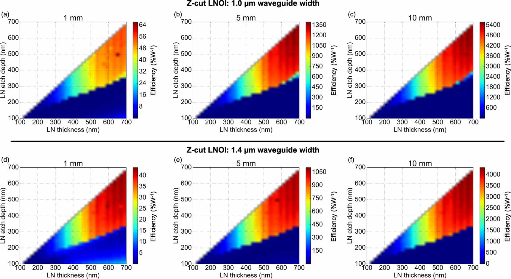
5. Discussion
In the previous sections the QPMs, SHG efficiencies and leakage loss conditions for X-cut and Z-cut LNOI waveguides have been investigated. The investigation showed that X-cut LNOI waveguides can achieve higher SHG efficiencies and require shorter QPM periods. Another observation is that the fundamental wavelength in X-cut LNOI waveguides does not suffer from lateral leakage for the investigated waveguide dimensions. However, there is a chance that the SH wavelength suffers for lateral leakage losses, which can be avoided by choosing an appropriate etch depth.
Z-cut LNOI waveguides are more prone to leakage. The leakage for Z-cut LNOI waveguides can be very strong and reach hundreds to thousands of dB cm−1 and needs to be avoided. A rule of thumb to avoid lateral leakage in Z-cut LNOI waveguides is to etch at least 2/3 of the LN thickness. This will avoid leakage in Z-cut LNOI waveguide for both wavelengths. The higher etching depth for Z-cut LNOI waveguides may also cause higher scattering losses, due to the increased overlap of the waveguide mode with the not perfectly smooth waveguide sidewalls.
Another point to note is that similar considerations also need to be applied for other nonlinear optical processes in LNOI. An example is the recent demonstration of supercontinuum generation in LNOI waveguides [28], which also observed the unwanted leakage of short wavelengths into the slab.
Silicon nitride (SiN) loaded LNOI waveguides have also been demonstrated in X-cut LN [14, 19]. The SiN has a lower refractive index than the LN, which results in weaker confined optical modes. The weaker confinement might make SiN loading less attractive for waveguides when Z-cut LN is used, as the waveguide mode index will be lower than in the investigated cases in figure 5, which may make them even more likely to suffer from lateral leakage loss. However, such waveguides might be very interesting for investigating and demonstrating bound states in the continuum [29, 30].
Overall, periodically poled Z-cut LNOI waveguides are very attractive for nonlinear optical applications although they have a lower nonlinear optical efficiency and are more likely to suffer from lateral leakage, as they offer periodically poled curved waveguides, which is very attractive for nonlinear optical resonators [7]. Furthermore, in traditional LN waveguides (proton exchanged of titanium diffused), Z-cut LN was very attractive for electro-optical modulators. This was due to the higher electro-optic efficiency in Z-cut LN waveguides as one could bring the waveguide into closer proximity to the signal electrode (high electric field strengths). This benefit might be less pronounced for electro-optical waveguides in the LNOI waveguide platform as the optical waveguide mode is more confined and the electrodes can be brought closer to the waveguide. A downside of Z-cut LNOI waveguides may be that the TM mode would need to be used in order to employ the large nonlinear optical and electro-optical coefficient in LN. However, the TM mode is less commonly used in PICs, as it has traditionally suffered from higher waveguide losses.
6. Conclusion
We investigated the SHG conversion efficiency and the impact of lateral leakage in X-cut and Z-cut LNOI waveguides. We found that Z-cut LNOI waveguides are more prone to exhibit lateral leakage and the SHG efficiencies in Z-cut LNOI waveguides are slightly lower. The easier and potentially more controlled manufacturing process of the QPM pattern as well as the potential for curved periodically poled waveguide for ring resonators might outweigh the lower SHG efficiencies in Z-cut LNOI, if one avoids lateral leakage pitfalls by choosing the appropriate waveguide dimensions. Furthermore, Z-cut LNOI is also very attractive for the integration of other PIC components such as acousto-optic and electro optic components. Hence, we believe that both cuts are attractive for PICs and one may pick either on, depending on the requirements of the specific application.
Acknowledgments
This research is supported by the ARC DP190102773 and DP190101576 as well as DARPA MTO DODOS contract (HR0011-15-C-055).